Greetings m8
I have a long issue with the laptop of my gf, as usual, the BIOS got corrupted from a voltage spike, the first things i tried to do are as follows:
1. The First things
The computer is cycled at startup, it turns off for a moment, turns on again, the keyboard (which has lights) does not turn on, the Shift key stays on and the power button gives two blinks, extra to this, the load led gives 8 amber blinks.
I assumed that as it gave me code 2, the BIOS was corrupted, I tried to enter the CMOS restore mode with win+B and power on, but it stays eternally in the cycle.
I assumed that it was not win+B to enter the BIOS recovery, then I left the power button pressed for 20 seconds, then the laptop reacts and the keyboard turns on, but still no video, and after 5 seconds it turns off again and returns to the cycle.
I tried to do the power drain, remove the battery and disconnect it, and leave the power button pressed for 30 seconds, but when I plug it in without the battery, the blinks cycle continues.
For that point, i assume to reprogram the BIOS with my CH341A Pro, and, the second part start.
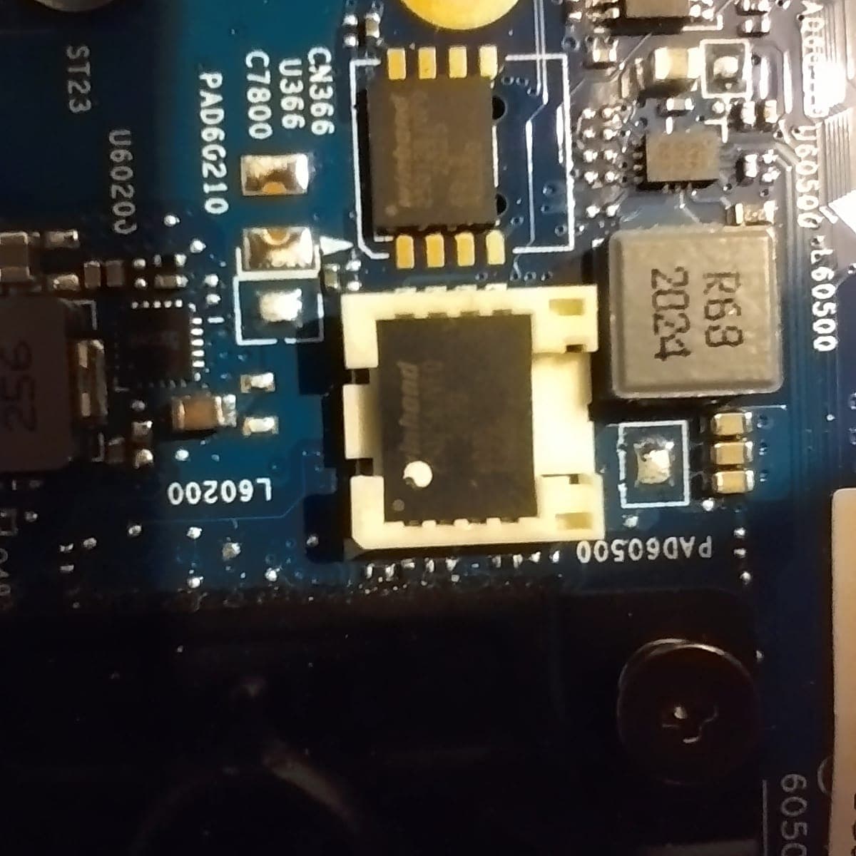
The Probook 640 G5 has 2 Chips Winbond W25Q256JVEQ(The CH detected it as W25Q256FV)
IMAGE 1
2. Reprogramming the BIOS
In that point, i thing the problem would be solved with a simple reprogramming on the chip, i search a healty .BIN file on internet and i downloaded it.
Before im started to reprogram the chip, i make a backup(i cannot upload it cuz im new :c ), and i reprogram the healty bin file on the BIOS chip.
For my surprise, the notebook startup on the BIOS update screen, but, for my disgrace, the pc decide to shut off in the middle of the update
Now for that point, i think i f*up the Chip, is one of my assumptions
But, i didn’t want to give up, and i search more deeper.
3. Learning about CSME
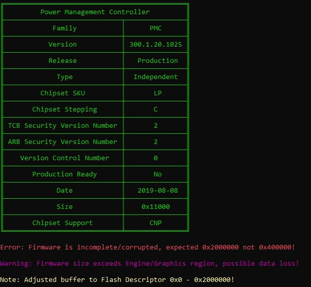
One technician on my local Tech Square say to me about using MEA for detect the problem on the .BIN file, and that’s why i ended up here, i read my first .BIN file from the backup i made before the reprogrammation, and i see the next prompt:
IMAGE 2
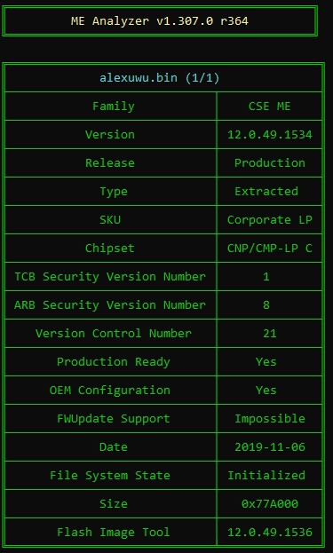
IMAGE 3
I tried to understand that information, and i ended on the forum from plutomaniac about the CSME and all the thinks from BIOS.
I tried to make another .BIN file for the probook, but i given up yesterday, cuz i pass all my time on that.
Today, i ask to my ITI teachers about the problem, and one of them says to me that I had to test by booting the computer without bios and without ram, now i tried it, and for my surprice, the PC replied
4. My last hope
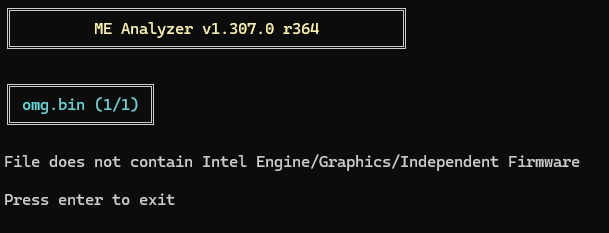
I tried again to reprogram the BIOS chip with the Healty .BIN, i put on the notebook, and i startup the PC without ram, i turned on, and makes 2 shorts beeps and 2 large beeps, im extracted the chip once again, and extracted the .BIN, the MEA launch me the following error
IMAGE 4
i search the problem, but i didn´t find an answer for my specific problem, i read in another forum from put the .BIN on UEFITool, and the tool launch me the next:
IMAGE 5
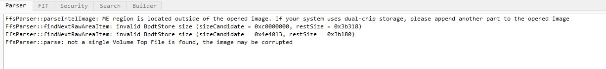
I don’t know what to do, because another teacher told me that the north bridge may have burned, and I am in doubt as to how to proceed.
What can I do?
sorry if i didn’t upload the images normally on the post, i cannot cuz im new lol
all of it was on the .rar on the comments