hello,
i just briked my Lenovo Thinkpad 8 Tablet, trying to update the BIOS
i know that is possible to create an USB recovery key , and boot from the key,
but i tried and seems the Tablet does not see the USB key during boot (or it is not in the right sequence)
i know how to disassemble my tablet, but i dont know which is the BIOS chip
perhaps someone can help me to find the BIOS chip?
and i need to know if with an EEprom writer i can write the bios after desoldering the chip
i need also the BIOS firmware, obviously, do you have the original (or modded) bios firmware?
Let me know, thank you!!
Lodovico
@vicolodo - First, did you format your USB to FAT32 and put BIOS on root of USB (not in folder)? I don’t know anything about the recovery method for this system, but those thing need to be done for sure, and usually BIOS must have a certain name too
Often some special button or key combo needs pressed while powering up, but not always. And BIOS would need extracted from the exe too, so if you didn’t do that then it would never work
Please link me to your BIOS download from Lenovo, or give exact full model name from sticker on system, and I will see if I can find you this special name to rename your BIOS to.
If you want help locating the chip on the motherboard you need to post some images of the board, put them all into a single zip or 7zip archive and upload to free file host or attach here
You do not need to desolder the chip, although you can if you wanted. You can leave it in place and use SOIC8 test clip with cable, let me know if you need a linked example of this.
@Lost_N_BIOS
thank you very much,
my lenovo Thinkpad 8 serial number is:
MP-09VKA6
i paste here the answer i got from Lenovo support, about my question on firmware needed and hardware parts:
"“
You can find the BIOS firmware here (link: https://lnv.gy/2x4P630) lnv.gy/2x4P630. Checking the parts lookup page (link: https://lnv.gy/2x5A6Sl) lnv.gy/2x5A6Sl, the part number for the system board is 00HW065. You may find the Hardware Maintenance Manual helpful. Here’s the HMM (link: https://lnv.gy/2x30WKO) lnv.gy/2x30WKO. Let us know if you need more assistance. -Maru_Lenovo
”""
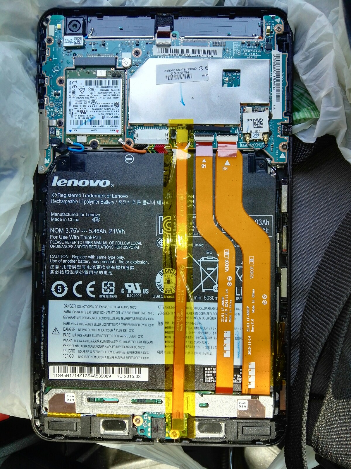
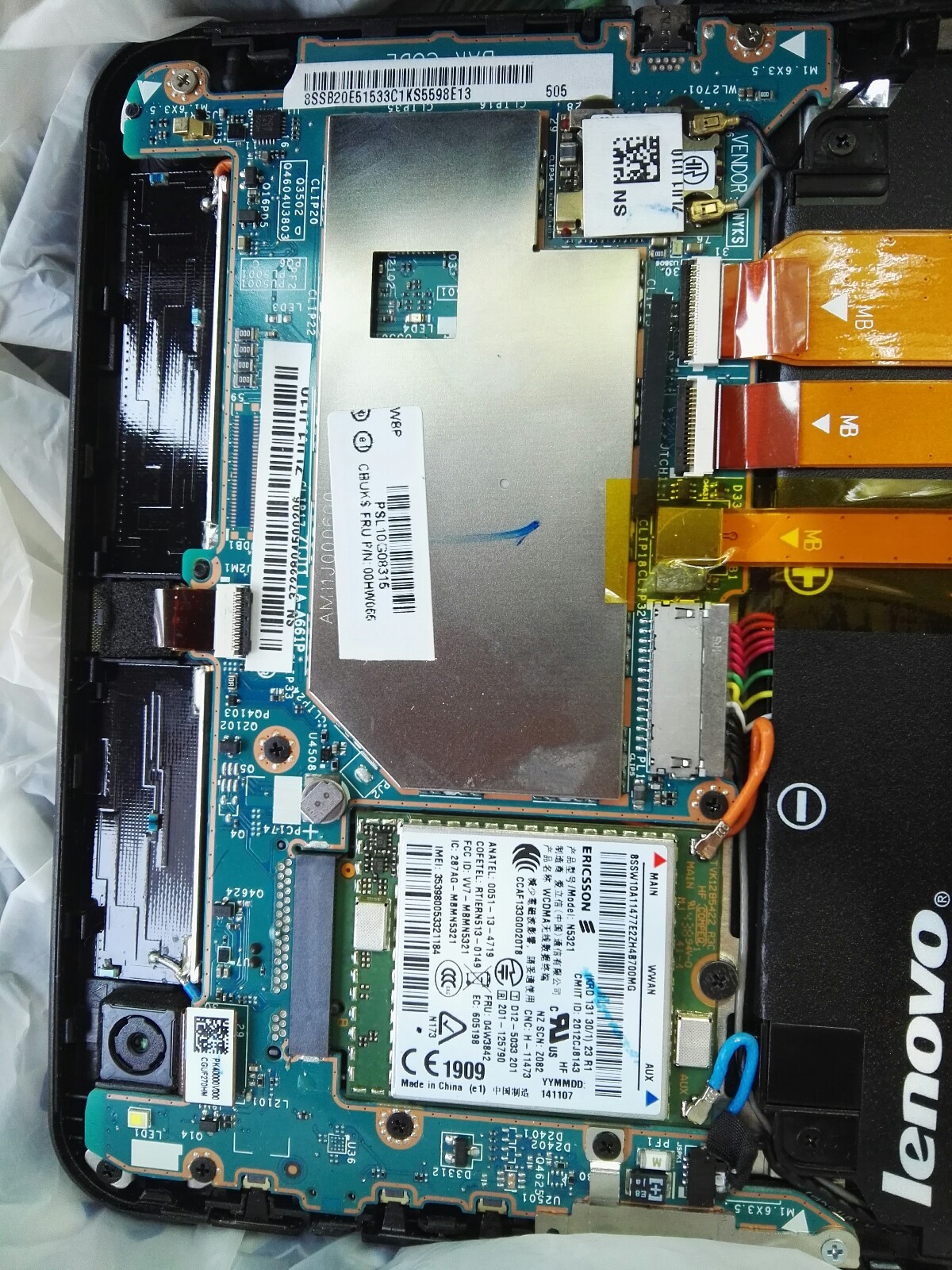
and i send in attachment two snapshots of my tablet after removing the back cover…
I am a newbie, to begin i would like to know :
- if an eeprom programmer like the ARCELI EEPROM USB Programmer CH341A can be used to write the Thinkpad 8 UEFI Bios
- if the BIOS file that Lenovo provided to me, that is an .exe, can be used to extract the firmware to be written in the chip (i know that from the .exe can be extracted a .CAP file)
- i have a windows pc (fujitsu core i5 8gb) with windows 10 64bit, i would like to know which software i should run on this pc to write the firmware on the chip
Sorry for the many questions, thank you again!!
Lodovico
@vicolodo - Thanks for link to BIOS. Do you use 32bit or 64bit windows, in case both those BIOS are different - it’s odd how they have it like that.
I do not know that Arceli programmer, but I assume it’s fine to program with, can it use normal CH341A software? - http://s000.tinyupload.com/index.php?fil…257455007472602
Here is guide on setting up and using if you are not familiar with programmers (not same as yours maybe, but cable and setup should be at least similar.
[GUIDE] Flash BIOS with CH341A programmer
https://www.bios-mods.com/forum/Thread-G…341A-programmer << Same as one directly above, but with all images expanded/visible at once
No, you cannot write .CAP BIOS into chip, BIOS needs to be removed from capsule first. And, if you do that without editing it, you will loose your serial, UUID, LAN MAC ID etc.
Plus, I have not looked at this BIOS file yet, waiting on above answer, it may not be complete BIOS and could be only a partial upgrade file instead.
You’ll need to dump chip and confirm it’s a proper valid dump before you erase or write anything though, so be careful and do not erase or write until you’re sure you have a confirmed backup someone has checked for you.
BIOS chip is not visible in the images you provided. It may be located under the battery, you’ll need to carefully undo those yellow ribbon cables and then remove the battery and send new images.
For the top two on second image, with white slots, the black piece behind there you push it forward/away from the cable, and that will release the cables.
The third one below those two, I cannot tell how it releases, possibly lift tape and lift the cable directly upwards, you’ll need to inspect and see, be careful.
BIOS may also be on backside of that visible board, especially if you can already tell there is not board under the battery.
If this is the case, and you can tell, then no need to remove those cables discussed above, instead remove that board itself so you can inspect the backside.
From the maintenance manual, it does look like the currently visible board is the only/main board so you probably need to check back side.
Sadly, it may also be underneath that sliver heat shield and that’s not removable without breaking it.
hello,
@Lost_N_BIOS
it was easy to remove the shield, it was hold in place with small clips all around the shield
i attach two snapshots that show what there is under the shield
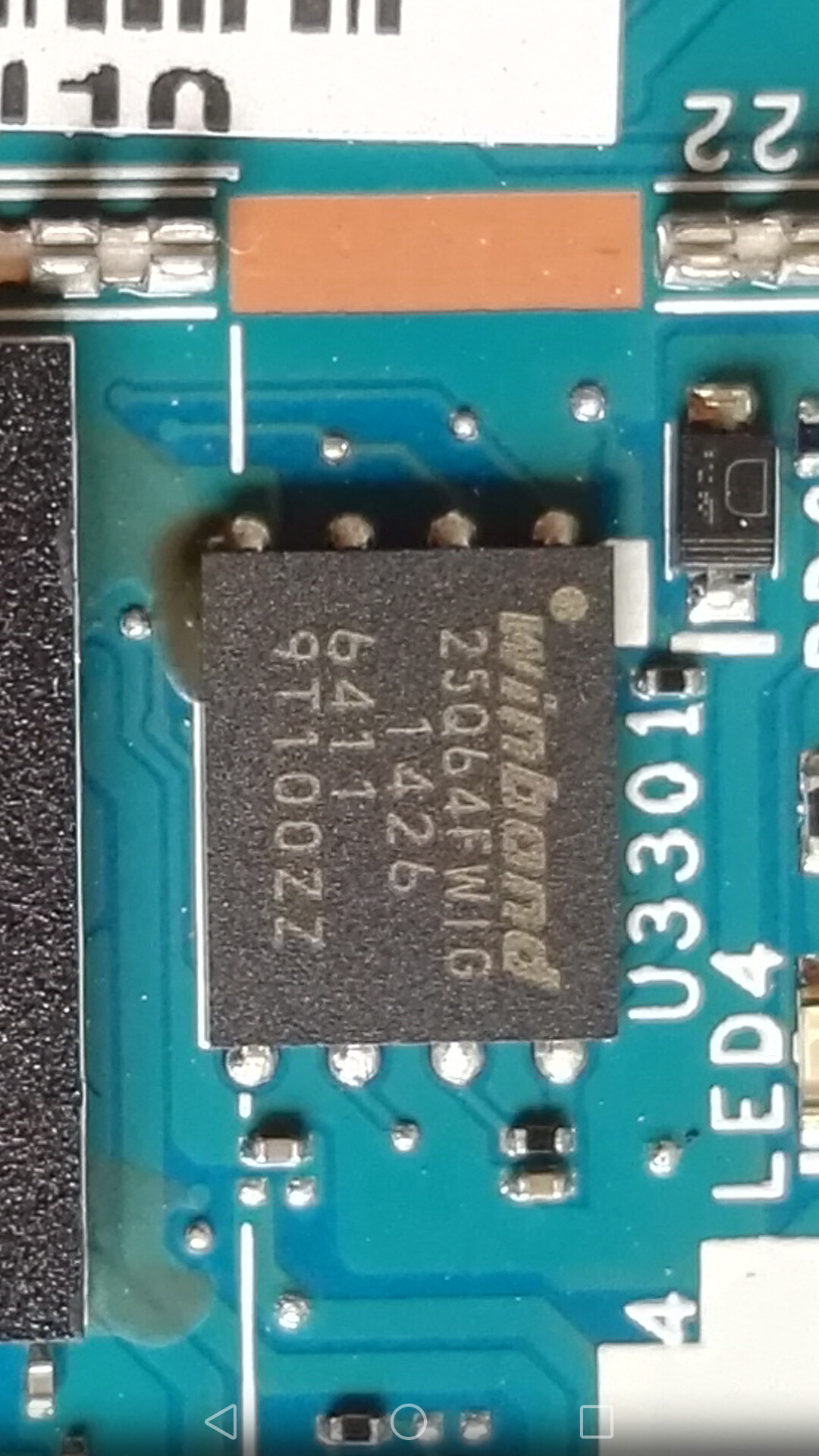
The BIOS seems to be the 25Q64FWIG,
i am right?
Let me know, thank you!!
Lodovico
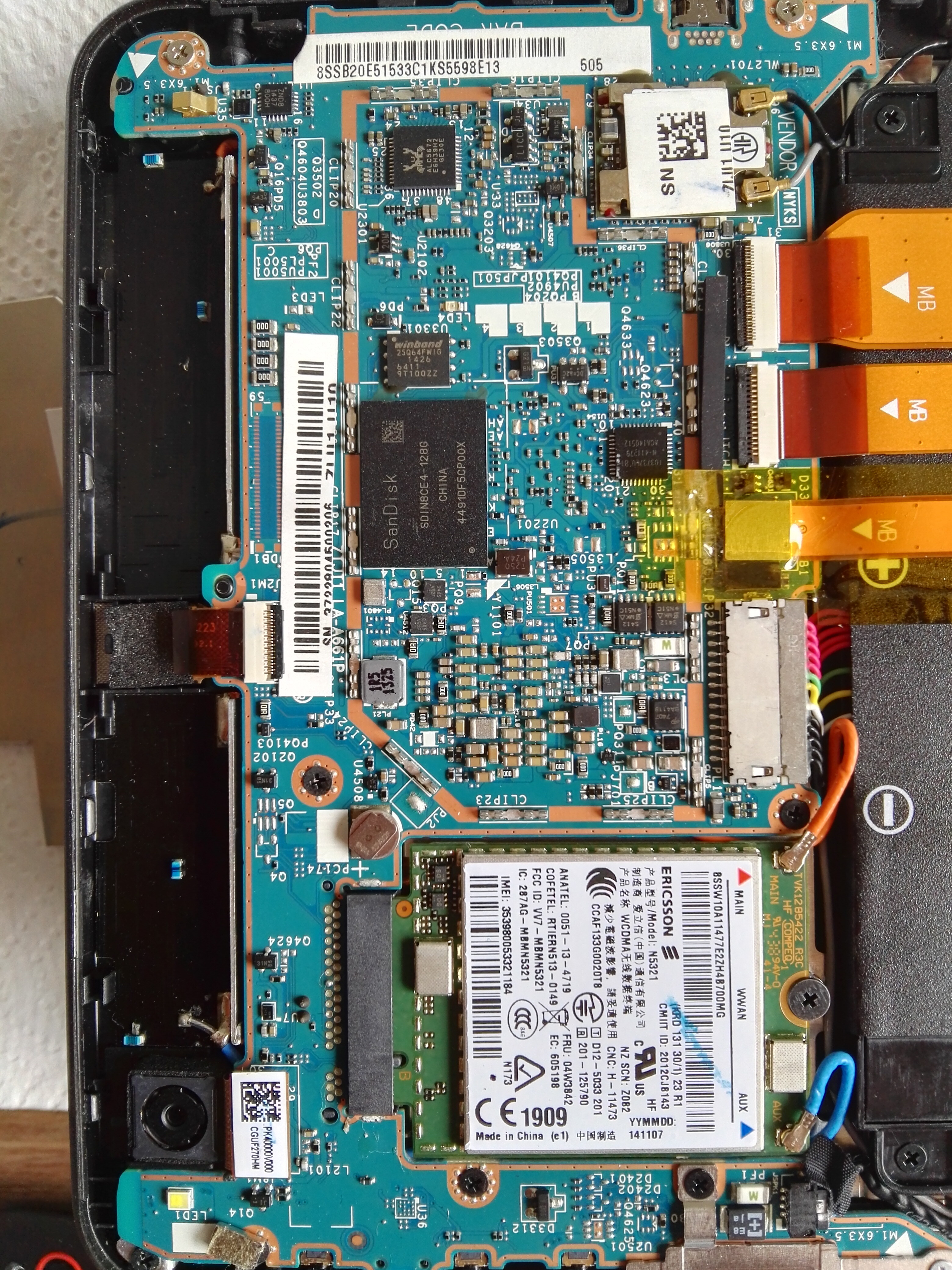
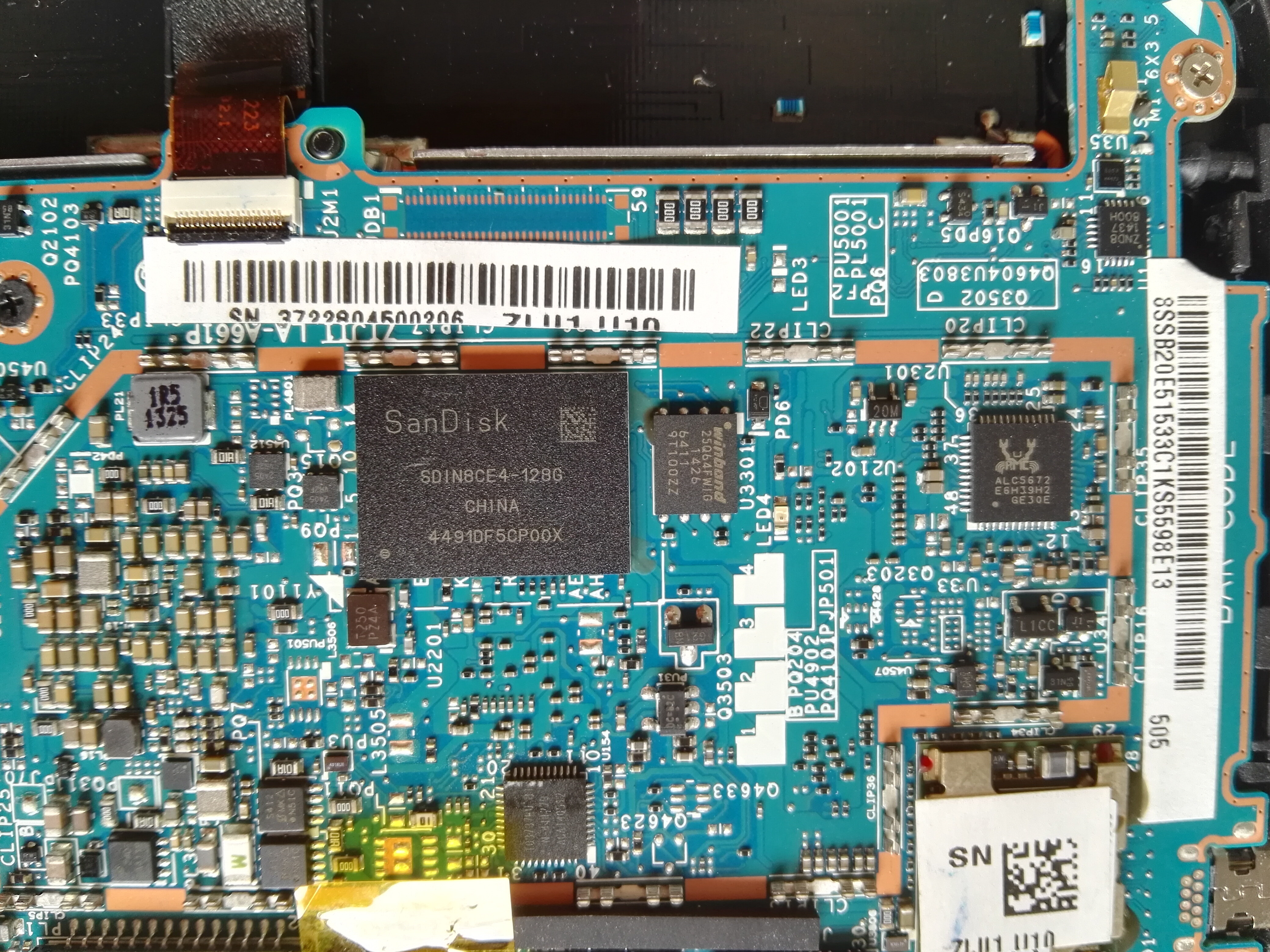
Good that came off easy, I couldn’t tell if it was soldered in place or glued etc.
Sadly yes, that is the BIOS and it’s WSON package, so you cannot connect to that with clips. I would need removed via hot air station by a professional (so other items near it are not moved/lost etc)
Then it can be programmed via CH341A clip or by soldering to the side/back of the CH341A, then soldered back into place once done via hot air and solder paste
Or it can be removed and a normal SOIC8 BIOS package soldered back in it’s place, then you could easily clip to it whenever needed.
It is possible, probably, to reprogram it through one of the ribbon cables, but I doubt Lenovo will share that information with you.
thank you,
@Lost_N_BIOS
i am not expert, but i have some tools that can be useful for soldering in very little space… like a Weller soldering station with very thin tips, a hot air gun, microscope and magnifying glasses for electronics, so i think i could solder thin wires to the pins of the bios chip…
or do you think it is better to desolder the chip, program it, and put it again in place?
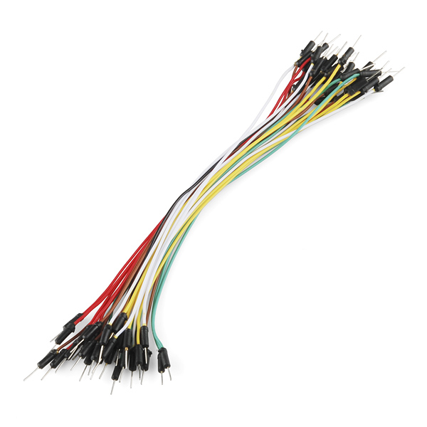
i have some arduino jumper wires like those in the attached picture…do you think these can be soldered to the pins?
(yes, i know, it is an hard work…)
but in a way or in the other, i think i will be able to connect the pins to the CH341A.
If i leave the chip on the mainboard without desoldering it, do you suggest to disconnect the battery cable from the mainboard?
Then , the last questions, about the needed bios files:
i found a tutorial on youtube, this tutorial:
that shows how to download the bios update .exe from Lenovo, extract from it (running the .exe) the .fl1 file.
I already did it, so i have the .fl1.
Now i have to read from the bios chip (using the CH341A read/write software), save it as a .bin file,
then edit it with a .hex editor like is shown in the video?
In the video it is shown that the final bios file should be 8000 bytes, this is true also for my bios?
And in the video i see that the guy searches in the file some start/end markers , to understand which is the block that must be copied…do you think that the process is the same also for my bios? the markers are the same?
and, finally, which software i have to use with CH341A, to read/write the bios?
I am sorry for the many questions, let me know…
Thank you!!
Lodovico
This is soldered underneath, must be reworked with hot air station and ideally a heating plate as well to warm the board overall as you apply heat to the chip itself.
However, yes, if you think you can connect to each spot on the side where the pad extends out, and not short things, then that will possibly work and allow you to reprogram it.
You can “Wipe” across or away with lots of flux to undue any shorts that happen while you work (wait till end).
There is no pins here, only bare solder pad and then possibly a little solder spilling out the sides from excess paste used. So I doubt a jumper/grabber will work for you, but a very thin wire directly soldered to each position would.
Those pins are too big, remove pin on BIOS targeted end and expose 2-3 strands of copper wiring twisted together. Connecting the wires to CH341A on the other end would be easy, insert the pre-pined end of each wire into socket and clamp it down same as a regular SOIC8 test clip with cable, or a socketed BIOS type.
Some systems need battery and power removed, some need them in place, only way to find out is to try once you get it all connected. I would leave main battery and power connected, but not powered on, for first round of attempted dumps
Sorry, cannot watch a 12 minute video, it may or may not apply to your BIOS. No BIOS would be 8000 bytes, that is only 32KB’s, you probably mean 800000h in length, this is 8MB, which is a normal BIOS size but may not be for your BIOS, I’d have to check
Give me a link and I will get you BIOS to use (Actually, I remember it’s linked above, still waiting on your system type 32bit or 64 bit, in case BIOS is different), but you will want to edit it other than the video shows I’m sure, otherwise you will loose your NVRAM, Serial, UUID, LAN MAC ID Etc.
First thing to do is open all software versions and on the “auto” function, uncheck erase and blank check, this way nothing gets accidentally erased. Then on the “Operate” menu for each, second tab 25/26 function, make sure only “Main Memory” is selected.
Then goal is read, verify and then if buffer or main memory and chip match save the file. Then check this file, is it all FF or 00 or same similar set of characters only, if it is that’s invalid dump, try again with different software. Send me the file once you get a good dump, it will look “similar” to the stock BIOS but not same. YOu can also compare in BIOS tools such as UEFITool, or AMIBCP 5.02.0023 or 0031 - good BIOS dump will look similar to stock BIOS in those tools, but not same, bad dump will not open or will show a bunch of errors vs the stock one in UEFITool parser tab,
Do not erase or write anything to the chip until I tell you we’re ready,
Here is software http://s000.tinyupload.com/index.php?fil…257455007472602
And here is a guide on how to use and setup (if you had SOIC8 test clip and were working on SOIC/SOIP type BIOS, think of the cable as your “wires”)
[GUIDE] Flash BIOS with CH341A programmer
https://www.bios-mods.com/forum/Thread-G…341A-programmer << Same as one directly above, but with all images expanded/visible at once
hello,
@LOST_N_BIOS
thank you!
my system is 64 bit
this is the link to the bios datasheet
https://www.winbond.com/resource-files/w…revd_032513.pdf
it is 1.8V , so i bought a 1.8V adapter for the CH341A
the correct stock firmware is
https://pcsupport.lenovo.com/it/it/produ…nloads/ds100744
if you run the .exe on your pc, and the end uncheck the actual installation, it will create only a folder on your pc, under the path …/ DRIVERS /…
in this folder there are some other .exe ‘winflash’ etc… and another folder, named as the update utility name, in which there is the firmware (or part of) , with extension .fl1
in the video above i saw that this .fl1 must be copied and pasted (using an hex editor) in specific position into the original .bin extracted reading the bios chip…
i thought that using the old firmware as base, and overwriting only the .fl1 section, should prevent to overwrite the important data (serial number, mac address etc) you told me…
isn’t it?
let me know, thank you!!
Lodovico
Good you picked up a 1.8V adapter. Yes, I gave the BIOS download page above, but there is 32bit and 64bit BIOS package, so wasn’t sure if that was only due to OS Type or BIOS type, since any 32bit software will run on 64bit there’s no need for two different packages, that’s why I paused for you to confirm.
I already know all about BIOS extraction, modifications, rebuilding etc. so I can easily grab all the BIOS file contents.
I cannot confirm that video’s method, since I didn’t watch it, but since it’s not for your exact system I doubt any of it is correct or applies directly to you. For any kind of confirmation about what you explained, I need a dump from your BIOS chip, then I could guess if it’s correct or similar method.
However, you wouldn’t want to do that anyway, if done exactly as you describe and that is the correct procedure per this BIOS, you would loose all your board specific details if you do that (Serial, UUID, LAN MAC ID etc)
No, FL1 is nearly entire BIOS size, so I “assume” this is a stock copy of the main BIOS region in it’s entirety minus NVRAM/Padding and would have all FF or other stock placeholders in place for the board specific data areas, so you would loose all that if done as described, as I mentioned above.
Don’t write anything, or erase anything! Once you get it connected if you get that far, get some dumps and let me grab your details out of them for you before you try any kind of repair
ok thank you
@Lost_N_BIOS
i will provide you the extracted file as soon as it will be available… now its time of soldering ![]()
i can use a very thin and long tip,
the problem with this tip is that perhaps it can not be very hot at the end, and so it is difficult to melt the tin touching the pads… i wonder if heating the area with the hot air gun held at appropriate distance by some support, can help…
Pre-tin the tips of your wire, so you then only need to hold in place and touch with iron. Hot air may be able to do similar, or if you have solder paste that will work with hot air too.
If using hot air, be very careful you don’t loosen other tiny resistors there and blow them away (I use kaptop/polyimide tape to avoid this when necessary)
For what you need to do here, I would use soldering iron not hot air.
There may be empty position on the board to connect SPI Cable/connector, look on both sides of the board and see if you find a place with 4-8 bare pads next to each other. Probably not since this is such a small board, but you never know.
hello @Lost_N_BIOS
sorry…so much time after last post ![]() …
…
are you still reading this forum? i need still help…
Good news:
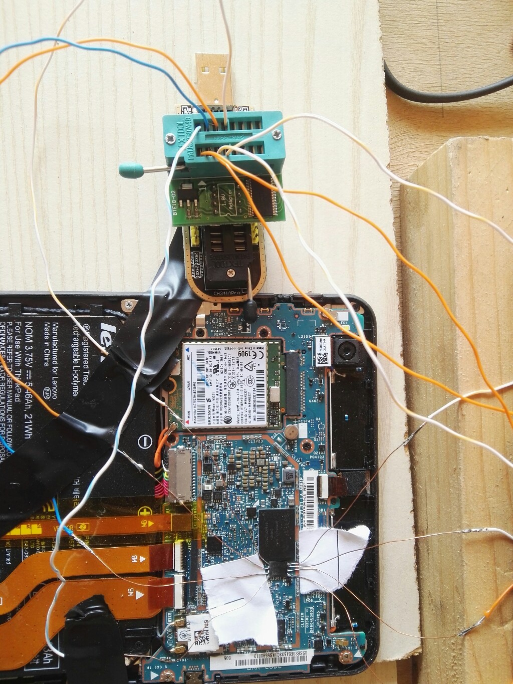
i was able to read the bios,
soldering the 8 thin wires on the sides of the wson chip.
So now i have the bios file.
The strange thing is that when i read the bios, the programmer can detect the chip only the first time , then after read (and verify) the programmer can detect the chip no more.
I have to wait a lot of time (days) to be able again to detect the chip.
I suspect that this depends on the fact that some current charges something on the mainboard (perhaps the small backup battery) and after that i have to wait that it discharges to be able to read it again… what do you think?
Hello hello,
i have found your problem when i searching for my problem ![]()
Soo i can help you with your bios flashing problem and then maybe you can help me ![]()
Attached is my fresh bios image dump…my unit is booting into bios without problem.
For bios dump and flashing you need any bios programmer with 1.8v adapter as you known.
You can use ch341 without problem BUT is better to use another software - asprogrammer sw is working well.
Always is better to desolder bios because when is soldered you can have problems with read/whrite due connected another parts on mainboard. You can test to flash it soldered, but will be needed to have connected charger and tablet must be off.
When writting in asprogrammer select ic 25q65fv/fw and unprotect-write-verify.
thats all ![]()
Now my problem.
i have this tablet with fully formatted emmc - no old partitions, no recovery etc…so i need to install clean os.
I have tested approx all but i am unable to boot into install procedure.
Ca you or anyone help me? …tested w10 86/64, tested 86only , tested w8.1 all versions too and nothing…boot is rejected or tablet freezes on win logo. Tested with rufus and with media creation tool…nothing.
i am able to fully boot android x86 thats all ![]()
thanks for helps
thinkpad8.rar (2.72 MB)
hello,
thank you for the bios!
sorry for the late response…
i bought before another .bin file from an online repair shop (they prepared the file basing on my old corrupted (perhaps) bios, that i was able to read with the programmer)…then i was able to write it on the chip, but now when i try to start the tablet, the maiboard gets hot and the screen is still black)
but i would like to try to flash your .bin
i let you know if it will work.
did you solve your problem?
by the way, i found some aliexpress sellers that sell the whole mainboard at relatively cheap price… i wonder if it could be a good choice…
https://it.aliexpress.com/item/33043624474.html