Hello there everyone, silent member over here (more or a reader), but I’ll try to be active. The title of the question is rather self-explanatory and I think it’s enough to go by to answer the question, but I like to give a bit more details.
A couple of days ago I got a new machine, it’s an Acer A515-57 with an Alder Lake-U processor. I am not experienced in BIOS mods at all, but I’m keen on learning (and I have a programmer at hand), so I posted a request for a mod to unlock the advanced menu, if at all possible (and no rush at all, I’ll make another post commenting on the journey), in a different forum (MDL), but I think Win-Raid or BIOS-Mods could be more suitable, but I digress.
Long story short, there are 2 NOR SPI chips in the motherboard, one of them being in a SOP8 (or SOIC8, didn’t check the datasheet), small 1MiB, so I thought WTH, I doubt there’s all there. Next day upon closer inspection of the rest of the board I noticed a chip with markings similar to the ones I’m used to:
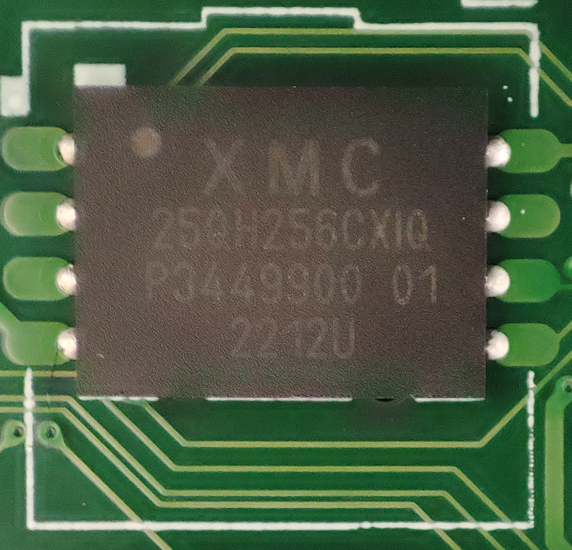
There it was! WSON8! I had never seen anything like that before, it’s a 6x8 so I ordered an adapter for those chips, both to (try) to read them as is throw a pogo pin contraption and a breakout one to solder the chip to; so in a couple of weeks I should be able to tinker with it all.
In the meantime, because those traces are covered by solder mask, but there, I started looking into replacing it for something easier to deal with; which is when I found out it is not as “simple” as checking the specs of both match (size, clock speeds, etc.), it also needs to be greenlit so to speak in the Vendor Specific Component Capabilities (VSCC) table.
Through the latest version of UEFITool I wasn’t able to easily see the IDs, but decompiling a firmware upgrade file in FIT (or Modular FIT as it’s called now) I could see 4 that are allowed:
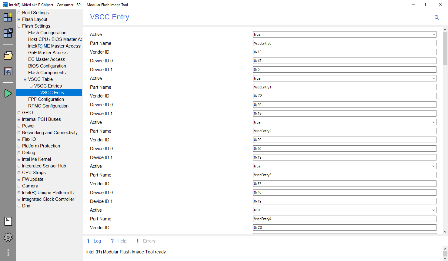
Entries 4+, while populated, are marked as inactive and I haven’t ever tinkered with this so I don’t know if one could just add an ID of a similar chip, set the active flag, rebuild, flash and enjoy. But! Entry #3 corresponds to a Winbond W25Q256[F|J]V class (it’d be the J, because it matches the clock speed) that I can acquire easily (the one that’s populated currently, the XMC, hard to get).
So! When the time comes for me to monkey around, in case something goes awry… could I desolder the XMC, flash the Winbond replacement with a known good dump of the XMC prior to any shenanigans and all is good? Or is there something else besides the ID of the chip and specs needing to match and be registered in VSCC?
Thanks for the read and everything, this could even be informative for those who don’t know of VSCC.