Try to take off the z490 board cmos, and use neoprogrammer 2.2.10 instead
Ah, but the chip is soldered on the MB… i’m trying with the clip.
But i agree that add a lot of variables to the equation… i don’t know if the electronic circuitry on the MB could change the communication, or even if my clip is functioning. I’ll have to make other tests to validate the clip, then other software’s to communicate with this chip.
Thank you all for the great support you give, better than a course! it’s the best practical work I’ve ever made ![]()
Instead of using the clip, you could try to use the asus SPI_TPM pins using dupont/arduino jumper cables like what i mentioned on post #14
Well, i think you’re right, that would lesser the clip8 variables.
However, there are some difficulties for me to connect to the SPI_TPM pins.
I don’t know the right voltage on it (i’ll have to make the measurement), i don’t have a device for plugging to the pins, and i don’t have a software to recognize the chip…
I’ve found a dell optiplex 3020. The chip is soldered on the MB (as the asus) and is a MX25L6473E.
I’ve downloaded different version of the ch341progammer, and the last one has this chip in his database. Unfortunately, my tests with the clip was a failure… unable to recognize/discuss with the chip. Ans the asus chip isn’t in the database either ![]()
I should make some conduct tests on my clip maybe, read notices again… nobody heard of locking systems on the bios chip? perhaps i should test them with the MB powered on (don’t like the idea)…
Still many paths to explore…
No and feeding more power to the circuit is always the LAST resource and NOT common on desktop mboards.
NeoProgrammer 2.2.0.10 has the MX25L12872F on his db.
Yes, i feared that would be a risky way. I won’t do it without good reasons or mastering of the process. ![]()
Apparently, the clip have very low chance to work when the chip is soldered on the MB.
That mean, the best way is to use the SPI_TPM pins…as mentionned by @Koekieezz ![]()
I need to by dupont jumper cables before having a try.
Thank you again for your support.
Yes, in this model the SATA ports are an obstacle. Users with soldering/desoldering experience will take it out to program.
Other will even solder direct conductor cables to each pin of the IC
There is “other kind” clips of the web from our ingenious CN citizens and their web market… not cheap not common not easy to find in some parts of the globe etc…
Well if the IC model is the one referenced before (MXIC MX25L12872F) by you… then its not 1.8V, its 3,3v.
![]()
I need some time to make the experimentation. We’ll see if that works, and if the 18v is indeed a 18v
Well, i finally sacrificed a old acer veriton l460 of my collection, to have a correct cable.
I was looking for the pin correspondances, when some details makes me wonder…
On the asus connector, there are the connections, i should use SPIxxxx
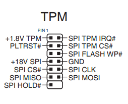
But there are 10 pins with the GND…
I suppose i don’t have to count the SPI TPM then…
SPI HOLD, SPI MISO, SPI CS, SPI MOSI, SPI CLK SPI FLASH WP,+18v SPI and GND would be the pitch.
But, looking at the MX25L12872F, there are those pitch reported: CS, SIO0,SIO1,SCLK,SIO2,SIO3,VCC and GND
Looking at the map, i see why the clip didn’t work… the pin assignment is different (the N°1 is not the vcc), so i should have to rearange that for the clip to have a chance to work…
Now, let’s figure out who’s who on the pin side.
GND,VCC,CLK,CS are easy to guess.
But MISO,HOLD,MOSI and FLASH WP vs SIO0,SIO1,SIO2,SIO3 ?
Maybe i should look into ch341a notice to try to understand the right correspondence?
You dont have to mind what are the chips on the board, if you connect the spi header on your board to your ch341a correctly (since both the tpm header and ch341a doesn’t say anything about sio0123), you dont have to mind your chip si0123, the tpm headers already alligned to your chip, so you only need to know where to connect from tpm to ch341a, and dont forget to take of cmos and psu must not be plugged in.
Well, today i used a multimeter to try to identify the connections by the measure of the resistivity.
The result is:
Pin N°1 of the chip (CS#)=>SPI CS#
Pin N°2 of the chip (SO/SIO1)=>SPI MISO
Pin N°3 of the chip (SIO2)=>not connected
Pin N°4 of the chip (GND)=>GND
Pin N°5 of the chip (SI/SIO0)=>SPI MOSI
Pin N°6 of the chip (SCLK)=>SPI CLK
Pin N°7 of the chip (SIO3)=>not connected
Pin N°8 of the chip (VCC)=>+18V SPI
Odd no? 2 pins not connected. Is it for the capacity? or for the speed of the data?
SI/SIO0: Serial Data Input (for 1 x I/O)/ Serial Data Input & Output (for 2xI/O or 4xI/O read mode)
SO/SIO1: Serial Data Output (for 1 x I/O)/ Serial Data Input & Output (for 2xI/O or 4xI/O read mode)
SIO2:Serial Data Input & Output (for 4xI/O read mode)
SIO3:Serial Data Input & Output (for 4xI/O read mode)
=> Maybe that means the connection on the mainboard is made for 2xI/O read mode?
And y need to make a measurement of the +18v SPI but i need to by a new battery for my multimeters, the number i get is not coherent.
On the ch341a connections, we can see there is no SIO2 and no SIO3.
And my multimeters reported: 3.3V… no 18v.
So i should be able to connect the ch341 with the SPI…
small pins, small connectors… i’ll have to take patience but the aim is close!
No luck on my first try…
i’ll retry later
Damn! this device is playing with my nerves!
My first try was to use an old connector made compatible with the spi on the board, using the 25xxx/24xxx locking system on the usb ch341a.
It failed, but i was unsure of the contacts ( loose ends of the bare cables are not easy to put in the right place, especially when the number is above 3…)
So y changed the bare ends to a dupond connector compatible with the one on the usb ch341a (the whereabouts of the pins are indicated on the circuitry)
I think the contacts are far more reliable, but i face a new odd
when the MISO and MOSI cables are pinned, the little led ‘run’ alights as soon as i plug the key.
And that makes the program neoprogrammer 2.2.10 fail when i try to detect the chip, or try to read.
More than that, that makes the driver fail, losing the recognition of the device in the windows i use to make my tests (a win 7, running with no driver certifications).
I used other programs but the driver fails too… the system is not reliable at this point.
Have you any suggestions? what driver are you using? have you heard of specific recommendations about the windows version or the good way to use it, because the driver isn’t certified. Maybe a linux would be more reliable? but what about the softwares?
Anyway, it’s still a tiny progress…
Well, i don’t know if those troubles are dependent from the other component of the mainboard, so i will try a different approach.
I’ve bought 3 unexpensives chinese chips: MX25L12872FM2I-10G (the exact reference of my bios chip) and i will try to program them outside of the mainboard.
If i encounter no troubles doing so, then it was the environment that produced those error, and i’ll cut (i don’t dare de-solder the chip) the chip and re-solder a new one on what’ll be the rest of the pin (hoping i won’t mess the multi-layer of the board this way…)
either it works, or the mainboard would be declared out!
@MeatWar @Koekieezz
Finally, y received the 3 mx25L12872FM chips i ordered.
I tested the recognition and the good function of my ch341a + clip with one of those unsoldered, new chip… and it works like a charm, no bugs, i was able to read the entire chip (full of zeroes of course, they are new) without bugging the usb key.
So, this is, you were right with the clip: to function, better unsolder the chip…
Now, i wonder: those chips are really tiny, i won’t be able to solder one of them on the mainboard without messing up the whole thing…but i should be able to cut the pins close to the chip. Maybe i could be able to glue the contacts of the new one on the remains of the pins on the mainboard? Anybody here to have experience with the conductive glue?
Whatever, i think the best course could be to attempt to force flash with the bios frankensteined by @Koekieezz . Either it works or could be rescued by the classical means, and i won’t have to cut and try to rescue the mainboard, or it completely fail => cut out, flash the new chip, and try to glue it.
No way! i tried to forceflash the modified .rom using the tool afuwin64 /GAN.
It seems to operate, but in fact, there is no modifications on the bios => can’t write back the modified ME.
Either there is a possibility to force the flash writing, or the only option left will be to cut off the chip and glue another to replace it
I can confirm ME update to 4.1 from Koekieezz rar package can be applied and works on Z490M-PLUS. But only that update do not allow to use 11gen CPU (I am playing with I5-11600k). I did not flash the “Frankensteined” bios yet (maybe it will need to be flashed with FPT).
My guess is that also have to update microcodes inside the bios area (if there are space to add new datas). So after initial CPU reset, the KBD controler can recognize the CPU and apply correct work safe voltage. Maybe the best way will be to do full dump with Intel FPT tool, then to make changes (hex diff between ROG-STRIX-Z490-A-GAMING BIOS 0901 and ROG-STRIX-Z490-A-GAMING BIOS 2103 and PRIME Z490M-PLUS BIOS 1621. ROG-STRIX-Z490-A have 16MB flash size too, but do not looks similar configuration. ROG-STRIX-Z490-G looks similar configuration but also do not have 11gen support interesting ), and then to reflash again with fpt tool ?
Interesting why asus do not add support for 11gen on all z490 main boards. Maybe there are mistakes on some of the board designs or they used other hardware revision chipsets from intel that will cause problems with 11gen cpus I dont know.
@Koekieezz does your “Frankensteined” bios have any param/microcode updates for the 11gen CPUs ?
It looks that’s due to board design… so no cross flash or mods maybe valid here.
This may spare users from the effort and searching in the future, seeking 11Th gen support on this model.
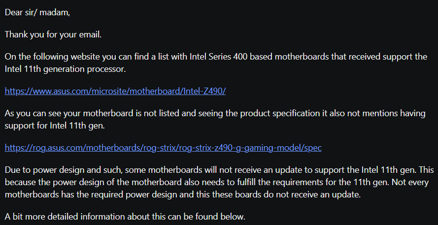
@MeatWar Thank you very much for providing this info !
I am not quite sure about the power design as they (asus I guess) stated in the reply. I5-11600 require same power as I5-10600. More like they responded just to write something. But the problem may sits in the data lanes wirings or hardware bug in z490 revision used in some of the models, or maybe in pci-e design (10gen cpu supports pcie gen3, 11gen cpu pcie gen4), or bios flash size (cheapest series z490 boards that support 11gen have 32MB (256mbit) flash chip, these that do not support uses 16MB (128mbit)), or DMI lanes wirings, or because 11gen cpus do not support legacy boot (only uefi - because the internal CPU
video card). There are many possibilities that we do not know. Some of them are trivial and will not affect the system work, some may make instability during work loads, or even hardware malfunctions.
At all the effort and the result maybe not worth it. Just from pure curiosity if it will work I may try swap cpu microcode/params of one of the current supported cpus with microcode/params of my I5-11600k if somebody can guide me where in the bios to look for this area and if there is way with intel fpt tool to reflash (or other tool) only that a specific part (maybe a sector of 512b ?) of the bios (flashing all the bios seems too dangerous and unsafe, desoldering/soldering too much work and time, and dont have programmer via tpm header).