Hello, I’ve just found this great forum and registered to learn and ask some help with my dead laptop.
I have read the content of the two flash ICs (U52+U53) using a CH341A and saved the dumps. I’m kindly asking your help to clear from the dumps the sections of the BCD related data.
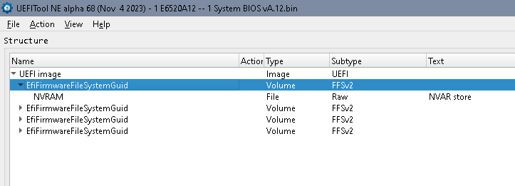
Based what I learned so far from this forum I managed to merge the two binary files and I was able to open it using UEFITool NE and see the content. But I have no idea how to proceed to have the BCD data removed.
Let me explain you what happened to my laptop. I have used EasyBCD under Windows to restore an earlier BCD store backup. I suppose while writing to the NVRAM the data got corrupted. After a reboot I pushed F12 to see advanced boot options and in the UEFI options 6 new, additional entries have appeared. I selected one of them and the laptop has hanged with black screen.
After that I was not able get further the Dell logo anymore after rebooting. The POST is completed fully, the progress bar fills, then the system hangs with the Dell logo displayed. I’m also not able to enter to Setup menu anymore or list the advanced boot options. If I press F2 or F12 during POST, I see the text appears on the top of the screen (“Preparing to…”), but then and system hangs again as soon as the POST is completed. Removing all disk drives from the laptop doesn’t change anything.
I suppose that this maybe caused by corrupt BCD data written to the NVRAM by EasyBCD, since the boot failure appeared right after restoring the BCD data. I hope clearing the BCD related data from my dump may solve the boot issue and make my laptop bootable again.
I would really appreciate if you could help me by removing the BCD info from my attached dumps. Or if you could give me any advice how to do it myself, or other suggestions how to solve this issue. SPI dump E6520.zip (5.3 MB)
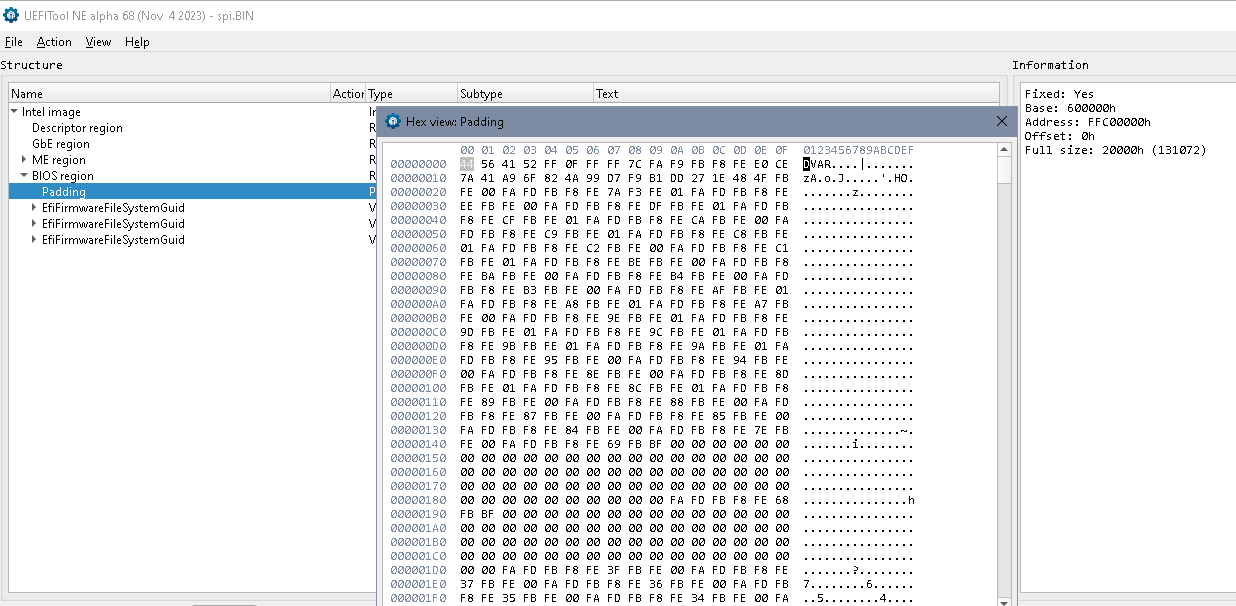
That’s “pre NVRAM”, there’s a NVRAM in stock bios but it’s getting changed to a DVAR region. There are 2 regions, both beginning with “DVAR”, each 0x10000 in size, probably used as redundancy. One might be good but not possible to know which.
You could exchange these 0x20000 with the NVRAM volume of a stock bios. The basic information should get recreated.
I have never modified the BIOS, it’s installed by the official BIOS update only.
I’m sorry, but I’m a very beginner in this topic and I’m afraid I don’t really understand what you suggested. Shall I copy some sections from stock BIOS to my dump? Could you please explain it to me in more details?
You might try those 2 files, but without warranty. This is a stock bios combined with the other regions untouched. There are some bytes that were changed in the 2nd EFI volume of your dumps, unclear why. So that’s my best guess. You have to program both chips!
Sorry, I forgot to write it, I’ve already done that. I kept a CMOS battery disconnected even for a full day, but nothing has changed after that, still the same issue.
I don’t want to seem to be disappeared, just having some technical difficulties to try those files.
I don’t have the proper tools for soldering and programming the SPI ICs and I don’t want to damage the ICs or my motherboard. I have ordered the proper sized SOP8 programming socket and SMD soldering tweezers. I need to wait a couple of days to receive them and then I will be able to try the files you made for me.
First I tried to read the flash ICs using it, without desoldering. But when it was clamped to any of the two ICs, the voltage dropped significantly, because the internal 3.3 V power bus of the MB draw too much current. The 3.3 V supply from the CH341A programmer has dropped to 2.2 V and the incoming USB line 5 V supply dropped to 3.1 V. As a result, the CH341A has disappeared from the Device Manager of the PC I was using for the programming.
So I suppose with this MB there is no chance to carry out in-circuit programming of these ICs.
Finally I desoldered both ICs from the MB using a hot air soldering gun and soldered them to a SOIC 8 - DIP adapter PCB, to be able to use them with the CH341A. This way I was able to read their content, which I have posted here.
Before I found this forum, using Google search I found some random dumps, which was supposed to be good for my MB type and revision (LA-6561P Rev: 1.0 A00). I wrote those dumps to the flash ICs and resoldered them back to the MB. But it doesn’t work, the situation is even worse, I can’t even see the Dell logo anymore, just black screen with that dumps I have found and tried.
I have not much experience with heat gun soldering and I don’t want to make more attempts with it to avoid damaging my MB. So to give a try for the files you created for me, I prefer to use soldering tweezers and also a SOIC-8 clip for the programmer. I’m waiting for these tools to arrive by courier.
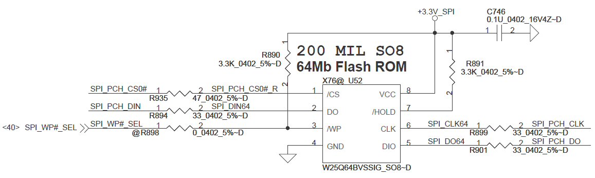
Well, a CH341 doesn’t need all lines, I’m always refering to an old Samsung board- take a closer look to all the lines, maybe it’s as obvious as fot the Samsung (Sandy bridge, too)
I think you don’t need pins 3, 4, 7:
Battery removed or not, sometimes a charger connected does help, but again, one should be sure that the clamp sits properly and doesn’t shorten anything!
Anyhow I carried out the following tests on the bulit-in ICs.
First I disconnected the IC pins 3 (/WP) and 7 (/HOLD). I made sure the clamp sits properly by continuity checking. When I connected the programmer circuit to the USB plug of the programmer PC, I measured the same huge voltage drop as before. Reading data was not possible, since the CH341A didn’t appear in the Device Manager due to the overload of the USB power line.
Then I disconnected also the pin 4 (GND) of the IC from the programmer additionally. This way the voltage level was OK on the programmer board, no drop. CH341A appeared in the Device Manager. I tried to read data from the flash using AsProgrammer, but I received only FF FF. This way the SPI IC haven’t received any power, there was 0 V between pins GND and Vcc. So it would have been strange to read any data from it.
And eventually using the last setup I connected the laptop charger and powered on my dead laptop. While it was on, I measured 3.3 V on the SPI IC power pins. But when I tried to read data, AsProgrammer still was giving me only FF FF.
After these tests I’m just still convinced that with this motherboard the only way to read and write the SPI ICs is to desoldering them from the MB. Anyhow please let me know if you have any other suggestion to try.
Sorry, I has disappeared for some time. I tried several things in then meantime.
First of all I managed to read and write flash ICs in the board, without desoldering it! I used your suggestion to disconnect the pins /WP and /HOLD. But it was not enough as I wrote it earlier. I read another advice reading through the topic you suggested me earlier. I connected external power supply with enough amperage to provide the 3.3 V supply while in-board programming. And this way eventually it worked, I was able to read and also write the flashes!
But unfortunately it was too late. First I wrote the files you created for me. Then I wrote back the original backup of my flash ICs. In both cases the motherboard seemed completely dead, it does not even shows the Dell logo anymore. When I switch it on, it activated the CPU fan for 15 seconds and then switches off itself automatically. Screen is just full black.
I’m afraid I have damaged my motherboard while I’ve been soldering the ICs several times. Since with the original flash content the Dell logo was displayed at least before I tocuhed the board.
So at the end I decided to replace the motherboard. Fortunately I found a second hand board of the same type ( LA-6561P) and I replaced my failed board with that. Now I have my laptop working again fine.
Only issue with the new MB is that the fingerprint reader doesn’t work. Dell utility says the finderprint reader is not connected. But actually it’s connected and properly shows up in the Windows Device Manager. Do you have any idea why could this happen? Could this be related some information stored in my old BIOS/flash ICs?
I have some progress with the BIOS files you created for me!
Now I have my laptop working again with the new motherboard, I couldn’t resist the idea to give a try to the files you sent me.
Actually there is a problem. A difference in the hardware reversion of the boards.
My old, dead MB version is: LA-6561P REV:1.0 (A00)
And the new board version is: LA-6561P REV:2.0 (A01)
Anyhow I dismounted again the laptop and connected the programmer as I explained in my reply above. I saved the original content of the two flash ICs and write to them the files you created for me.
Then miracle! The laptop started to boot!
But there was a problem. I see an error message right after the POST: “ME is in recovery mode". Then I was able to start to boot the selected operating system but when I was booting to a Windows on an MBR drive, after a few seconds there was always a BSOD.
Fortunately I was able to boot properly to another Windows on a GPT drive, without BSOD. From there I’ve tried to reflash the BIOS with the latest firmware, A22 using the Dell BIOS update software. The update completed properly and it did some significant corrections.
Now the selected operating system properly boots up, without any issues, even on the MBR drive. The system seems to work properly, I didn’t observe any problems. But the message “ME is in recovery mode" is still displayed for a few seconds during booting.
I guess it’s caused because of the hw version differencies of the two boards.
Could I kindly ask you to do anything about it? Or if not, what could be the drawback to leave the system like that? Like the ME error message is displayed during every boot, but otherwise the system is OK. Could I leave it like that?