Right to extract and work with CBS settings looks like this is what we have to do and figure out:
CBS cannot be done from the AMIBCP tool
https://puissanceled.com/vrac/Bios_modding/EN.html
Thanks! Yes, I was thinking of making Auto = 1 enabled too, but was unsure if that would create conflicts or stall out the BIOS having two different variables = same value for that entry.
Few places I was reading and people needed to change similar items, but not the same ie not 3 choices) they were editing the line here below
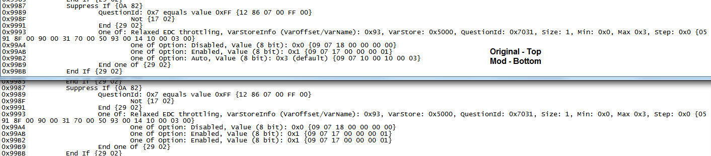
Setting: Relaxed EDC throttling, Variable: 0x93 {05 91 8F 00 90 00 31 70 00 50 93 00 14 10 00 03 00} << Changing that 03 near end to what they wanted, so that is what I was trying in above edit I laid out in full test at post #2
They were changing that and the 10 before that 03 (their examples were using ff to enable menus, but same applies to this only we needed the 00 00 01 which is what I set above string to in the try first folder (mod test2 BIOS)
I will make two more, one with changing the auto value to match enabled value, but leave that long string alone mentioned above, and a second with that also edited to match enabled values.
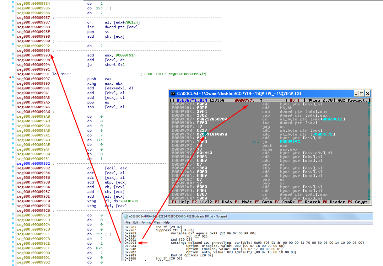
This editing is done by extracting the GUID that contain these settings A5E369C8-ABF9-4B43-B212-FF1BFD35666D and then locate above hex string and edit, value choices are directly following. Work checked before/after by putting that file into IFR extractor, then reinsert with UEFITool.
Thanks for the link about CBS menu, that guide even shows same GUID I was already editing. Still applies though about this file, I can’t add if not currently there because the file is 1000x more advanced than the hex images and text layout you see from IFR output there.
It can be modified as shown, easily, for what is already there, but even removing a line via hex that is shown in text does far more than that and I think it will break the entire file, it’s compiled in an assembler so adding or removing a line will break everything after that and probably before as well.
Modifying an already present value is easy.
Will edit in a new mod for you to try on EDC in few minutes, refresh and check here
Then I will look deeper into the CBS options for the Taichi and check Gigabyte one too and see if I missed it earlier due to not knowing this CBS method. Is the CBS options in Gigabyte board too for you, just missing the setting?
Maybe wait, I will check this first now, maybe the EDC setting can be enabled easier that way, or maybe that is the proper way to enable and make visible for this BIOS. I’ll figure it out that way, or we’ll try the other way later if I can’t.
* Well right away now I see that guide is same I was doing already, it’s too bad, and too bad also the visible/hidden setting is not there in this BIOS CBS like shown there.
Read paragraph at the end here from @ket that sums up the issue here entirely - [OFFER] Gigabyte GA-AX370-Aorus Gaming 5 BIOS mod (11)
Reading further into that thread, and their mods, I think it can possibly help me get this sorted out! Another user on page 12 @TOM_RUS discusses how to enable all CBS and gives BIOS files, so I will absorb all that, grab the files he posted and then see about getting same done for this BIOS.
That will take me a while to look over, I saw you in that thread too! 
While I look all that over, and compare those BIOS here try the simple change we talked about (Making auto=1 enabled) The CBS settings are different in those boards than this chipset, so I will need to compare those BIOS they shared with stock variants, and then see what I can do about the settings for this chipset.
If you are friends with ket or TOM_RUS maybe you could ask them to PM me some quick hints on editing for x470 vs x370  In general, I still think much of this editing needs to be done in an assembler, which I cannot do, but maybe I’m thinking about that wrong for only these changes
I already compared the stuff we mentioned changing, and it’s not changed in their edited BIOS, however that was not their goal (only force one setting to be set to enabled our goal, vs they enabled all settings and menus for user input).
So I think it still may be possible to change Auto in place, Value: 0x3 (default) {09 07 10 00 10 00 03} change to Auto, Value: 0x1 {09 07 17 00 00 00 01} and it may apply the setting change.
Still unsure, if only doing this simple behind the locked door change will need this variable string changed to reflect auto = 1 instead of 3? (05 91 8F 00 90 00 31 70 00 50 93 00 14 10 00 03 00 Stock) to matching end settings for variable 0x1 - 05 91 8F 00 90 00 31 70 00 50 93 00 14 00 00 01 00
We’ll see, test and let me know BIOS is attached, this is only auto changed without the long variable string changed. After changing Auto option hex values to = 0x1 (Which I did not set), I loose the (Default tag) that either has to be done in assembler, can only change hex values for the option line.
http://www.filedropper.com/newedctest2
Or my line change mentioned above could be the key (nope, tested and included, no change in IFR output = same as above image w/ the ending variable changes)?
I’m also now curious if removing Suppress If: {0A 82} before this setting simply unsuppresses it? I’d test myself if I had setup, but don’t want to send out blind removal of a line like that for someone else to get stuck recovering from. I know you can recover, but still. 
Remember, no need to hunt for BIOS setting changes, this is only internal test change, no new menus/entries added, I’ll have to read up and look into ket’s and TOM_RUS BIOS mods and see how/if I can get all that accomplished or not.
Can be flashed from Qflash! Thanks @ket for the tip on that
*Final Add-in for the night. See @POE_UK - here is what that CBS file actually looks like (not bin viewed in hex or text IFR output), from two different disassemblers. This is where the real settings are applied and changed. No one talks about how to play with this out in the open 
These are the exact settings programming, and same viewed location as all the other simple text images you see when someone mentioned IFR (When I posted Value: 0x3 (default) {09 07 10 00 10 00 03}, that’s from IFR simple text output of this highly detailed assembled programming file)
These images, two from dissasemblers, and one IFR text, all from the same single file and showing same location within that file. See, it’s crazy in there I need real guide, or some minimal tips and info on how to even start messing with any of that, you have to be rocket scientist to use these apps even with instructions 
It’s not a simple hex edit for this kind of changes
For the first time ever i was having a play with the ami bios editor, damn its fun, i have 2 3x120mm radiators in a dual loop configuration in my tower900 case, so i changed EC-TEMP 1 and 2 to RADIATOR CPU and RADIATOR GPU in the bios, as ive installed the thermal sensors to the rads, its now showing in the bios as rad CPU and rad GPU! excellent lol
Bloody hell mate that looks proper complicated i wouldnt know where to start!
Its beyond me why they made it so the CBS settings cant be edited in ami bios editor
Just going to test the bios you did here and thank you again, ill post back the results in half an hour.
EDIT:
No m8 still not working not to worry, seems until gigabyte adds the module it wont work, thanks for all your efforts though appreciated.
Maybe Ket could help us out here
Yes it’s always fun playing with AMIBCP, especially when you get to unhide some settings! Right!
I usually dive right in, start testing and modify, then double check my results and try a few ways if needed, but I can’t make any progress with the assemblers.
I think it’s mainly due to no one really discusses that or how they work and there’s no guides anywhere on how to use them for these specific changes either.
I even tried jumping right in and playing with the edit menus and functions, but couldn’t make anything change the way I though it needed to be, and couldn’t find what I thought was the right part there to be trying to set different.
I do think I can now see now to navigate properly through each bit and function there but that’s a minimal all I can gain blindly pushing buttons in there and then tossing out the file/changes.
If I could find a good, even short guide about using some of those apps, in regards to making these kinds of needed edits, I’m sure I could figure it all out.
I assumed that change wasn’t going to work like we thought, especially once I made the edit and saw the newly checked output didn’t say (Default) anymore after making Auto match Enabled via hex.
Maybe that same change would work if done in the assembler where I could either put back the (default) being applied or change auto (Default) to enabled instead of whatever 0x3 is instead of 0x0 or 0x1
I’ll try to figure out more tonight!
@ket hasnt been on here for a while now hope hes ok, yea that amibios editor is a fun tool, one thing i do like about gigabytes bioses is if you save your bios from the uefi to a usb drive, it saves the custom profiles too! also unlike my asrock taichi x370 as much as i freakin love that board, it doesnt save p-stste overclocks in a profile, so you have to manually set them every time.
I think there are pros and cons to any board, but once again i really cannot grasp the laziness of gigabyte, i had this problem on my x370 gaming5 motherboard with sloppy bios implementation and lack of support, this x470 gaming7 wifi board is just beautiful hardware and looks wise but once again its being let down by missing bios options.
I also used the amibios tool to remove multiple entries of memory settings that were showing up, pretty much customised the uefi now to my build and named the fan headers to where they are in the case instead of just, sysfan1 sysfan 2 etc.
EDIT 2: Its working!
" things you need to do to unlock EDC throttling on this board are:
1) Install The Gigabyte App Center (EDC On This Board Is Software Driven) this explains why when you were poking around in the firmware you saw auto setting IF code to enable it, that IF is IF appcenter and the c++ binaries are installed! Appcenter has the easytune engine service that enables everything, it can be un-installed after.
2) Install Microsoft Visual C++ 2010 x64 Redistributable x86 and x64 binaries
3) Update directX and directX 2010 Runtimes (June 2010)
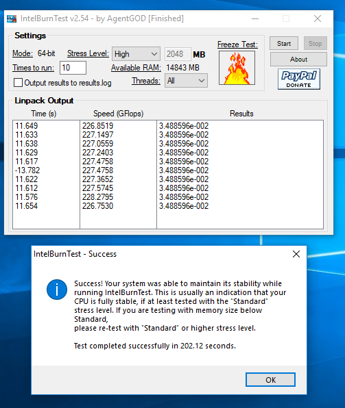
Before i did all this i got 186GFlops with intel burn test AVX, now im getting over 224GFlops!
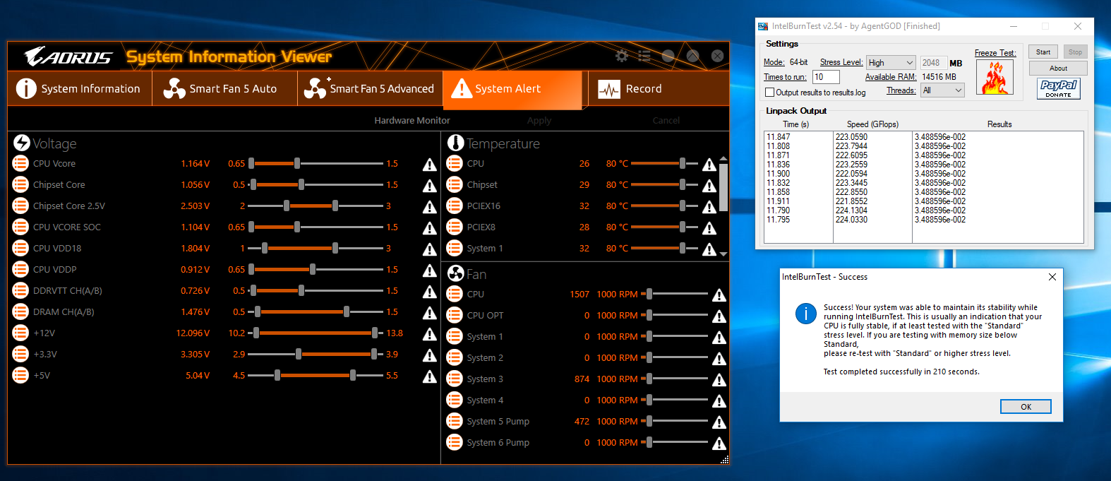
After a second run: @ 4.35GHz 3480MHz Ram Cas 14,13,10,11, 1T
Ok im a happy man now, its running fast as lightning mate, and thank you so much for all your hard work.
Cool that you edited your BIOS to match proper fan locations, it’s a great idea and simple one that should be done by default.
I agree, every board has it’s pros and cons, and same for brands, sometimes one brand is better than the other in a series other times that brand isn’t as good.
Sometimes too, the lesser/cheaper board could be better than the next higher up model.
Hey now! You’re welcome and that’s great news you found that EDC is working!
There is no “Auto setting IF” The “Suppress If” that appears on all setting entries, almost always, and is not related to this.
It may be working anyway if what you listed above is setup, but it may not be due to the stuff we looked at in BIOS editing, at least I don’t think so in the way you mention
Default setting of Auto may always work=enabled if what you setup, but it also may not be like that too, are you using stock BIOS now or modified one I sent?
Can you (will you please) confirm if the stuff you outline above was all you needed originally, or if one of the BIOS I changed made the difference?
You’d have to flash back to original I guess, but it would be nice to know on my end if the BIOS changes enabled or not.
If the BIOS changes did fix, let me know which one and I will edit that mod to also include the Fail_CNT fix for you too.
You could flash back to the FAIL_CNT BIOS I sent you to test if EDC still works in windows, it does not have any EDC attempted changes.
If EDC then isn’t working in windows you’ll know whichever BIOS you were using above from latest EDC change attempts must have fixed it.
I’m still alive, just not as bothered with fixing GBs mess ![]()
Thanks for the hello and update @ket good to hear you’re OK too!
Do you know any guide on how I can work with the CBS file in assembler, or general assembler guide that would teach me something in regards to this type of single file editing?
Hello again, all is well here its working great, i used the f4g from gigabyte - yea unless the software above is installed to talk to the firmware EDC wont work, the c++ binaries did the most
I asked gigabyte directly about this issue this was my response:::
Hello there, I have looked into this and seen that you can enable it through the GIGABYTE App centre and use the easytune to do it. Do you think this should be an option in the BIOS as currently it is software driven.
my answer was:::
Are you all on drugs or what? who the hell makes a common bios feature software driven, that means you cant overclock properly and are missing out on 20% of pereformance unless you are using windows10, and software crashes! you are a bunch of muppets, and you all deserve to be slapped around the face with a wet kipper.
Thanks for confirming, no EDC changes helped, only above in OS changes worked for EDC. Yes, only BIOS engineers would be able to help on this, support center techs would not be able to do anything except tell you to use the software or they don’t know etc.
Meaning the Fail_CNT edited BIOS is only valid BIOS to use in this thread, for anyone reading later, it’s in post #4 - <Request> Flagship X470 Gaming 7 Wifi Motherboard BIOS Fix
Its laughable really, its the most important setting to do any meaningful overclocks, anyways gigabyte are now looking into adding it to the CBS/Custom p-states/throttling menu where it belongs on the next bios release.
Hopefully they will come through for all the new X470 owners! They never did on X370 did they, you all had to rely on ket and other modders the whole time right?
Yep sure did ket has been a diamond to me, the x370 gaming5 is dead, an absolutely terrible board.
But i tell ya, this x470 gaming7 is an absolute beast of a board, i’m going to keep pestering gigabyte until something is done, its the only way.
Too bad he was tired of trying to keep up with mods for these, but it is tough work so I understand! I hope they keep updating for better BIOS for you all!
Please post back here if they send you any update BIOS, for anyone reading in the future, thanks!
I will do m8, ill post it on page 1, and change the name of the thread to <new bios>
Hello,
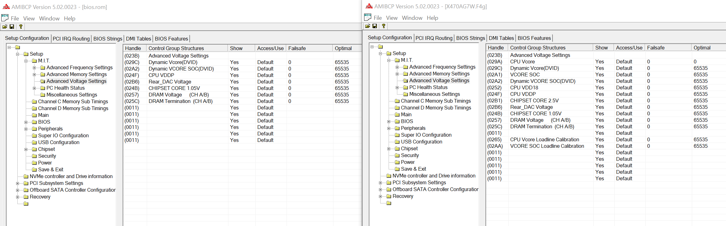
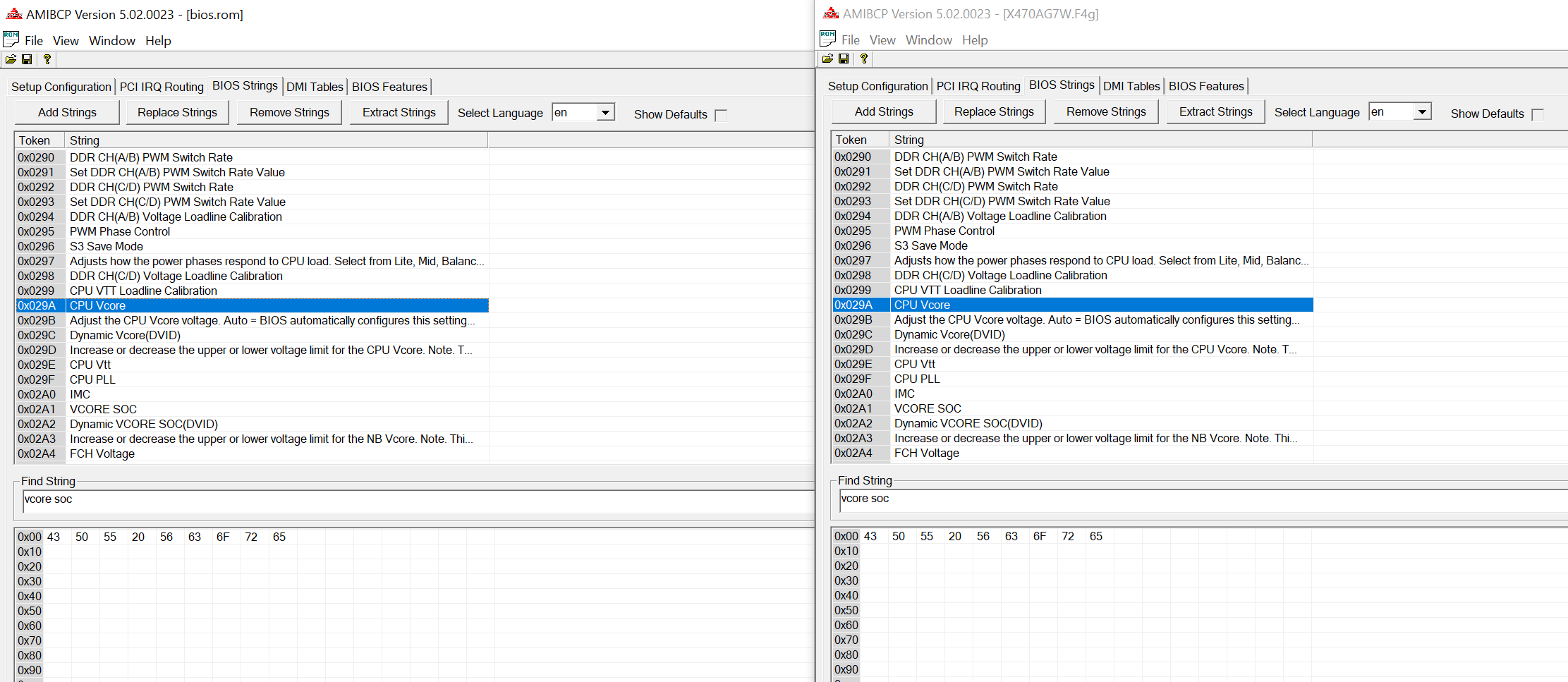
Is it ok if I would request for bios mod? I’m really afraid to mess things up to do it myself. Dear bios gurus, could you please mod X470 AORUS ULTRA GAMING board bios? I got this board and Ryzen 2700 with hope that it will be easy to overclock and get same performance us 2700x, and actually I do can but only in windows with Ryzen Master app. I’m easily getting 4100 ghz with 1.35v. Problem is that stupid board can’t start with native speed of my RAM which is Corsair CMK16GX4M1B3000C15. I have two of them and as soon as I enable XMP in bios board trying to boot few times and reset to default speed after all. I was trying to set everything manually but still no luck. Also some settings are hidden, like vcore and vcore soc and may be more useful stuff. I checked with AMIBCP this board and x470 gaming 7 bioses and in main menu in gaming ultra board those setting are hidden compare to gaming 7. And if I go to bios strings and look for them there and I can see it is there already but I don’t know how to enable them. It is even have a same token numbers. So probably both bioses are mostly identical just adjusted for a different price tag
Could you please help with this? Will really appreciate it. Thank you.
All what you show is/should be visible in your BIOS (BIOS.rom on left correct?) You can’t see Vcore and dynamic Vcore? If not, set that to “User” where you see “Default” then save as new file name and flash.
You will need to flash modified BIOS differently than usual, often USB flashback will work fine. Here is two guides.
[Guide] How to flash a modded AMI UEFI BIOS
[Guide] Flashing modified AMI Aptio UEFI using AFU
Be ready to recover from bad BIOS flash if BIOS mod fails, either CH341A flash programmer, or another board you can hot flash your BIOS with.
Unless your board has two BIOS you can switch back and forth with via a switch, then it will be OK you can always switch to the other and then reflash the messed up one.
Mate dont mess with the bios on these boards unless you know exactly what youre doing, even with dual bios it doesnt take much to screw them up, the uefi in gigabyte boards is very fragile and sensitive.
wait until gigabyte release an update, even windows can corrupt the bioses in these boards, especially when you start messing with VERIFIER a windows built in tool to check and disable driver signatures. so you have been warned.
Im using the aorus x470 gaming7 wifi and its running my 2700x at 4.35GHz with 3466 corsair rgb xmp ram cas 14,13,10,11,1t no problem whatsoever.