There’s always a way around. You can flash the SPD directly though a cheap programmer for instance. If the SPD is protected by the grounded write protect pin, you can desolder it and attach to VCC to allow flashing. If you can’t find the datasheet for SPD, you can replace it with AT24C02.
1.96v is not that big for those chips. If you read their datasheet, you will see that the max voltage is 2.3v (in the case of H5PS2G83AFR)
can you point me to that forum as I’m having the Nvidia GPU freeze issue on 3 of my Dragons and cannot seem to find the solution or figure out how to use the Powermizer app.
Thank you. I have 4 of these things. 3 With the Nvidia and 1 with the ATI. I was able to get windows 11 on all 4 running pretty decent. Now I’m looking at modding and improving them. I wish HP would produce an updated one of these, maybe as a tribute to the good old days.
I don’t know if this is the right place, but since I own several such laptops, the topic is a pain for me.
I’m talking to Remdale because I’ve read a lot of your posts and I know you’re a big fan, geek of this laptop. Great knowledge, dedication and humanity!
After reading everything, I see that people with technical and other capabilities are impossible to find.
HP has deliberately made this laptop as impossible to upgrade as possible.
The only thing I think we have left is to just put a foreign motherboard inside the laptop case.
You’ve probably considered this?!?
I’ve been considering it for a while too.
I’m thinking of putting in a foreign motherboard that physically fits into the case. There is room! The question is what happens next?!?
We cut the external connectors from the original one and put them in their place and connect them to the new one using adapters or soldering.
It will need a lot of tweaking, but as an idea, what do you think?
Sorry for the delayed response, I wasn’t notified about your reply until now.
That’s true that engineers are hard to find, especially for our laptop. Freelancers are the way to speed things up, but I’m not that rich. Moreover, it’s hard to find those who could become interested in upgrading this laptop.
It was another day today when I visited the local university presenting my idea of swapping a motherboard. I faced pretty much of critics against our idea, they said things like the idea of a big laptop is sick because the world has come down the road of small things and carrying a 10 kg laptop is not what the world wants. But I argued against their mind saying that if I want that and some other people want that too, then there’s a good chance that more people might want the same.
Thanks for cheering me up, mate. Humanity is what is driving me, but I’m still doing things alone as an engineer. I’m having troubles with my job which is not related to engineering in any way, so I have decided to switch off to developing some quick stuff for earning something for living. I’m talking about circuit boards for synthesizers which I’m going to sell to repair shops. 2 of them have been sold already on Ebay over the past month.
A good idea has come up in my mind though. If our community could sponsor me each month, I could switch back off to our Dragon. Core 2 Quads can’t be installed, the guy I’ve mentioned before has given up on that. He can’t find the right way to replace the APIC table. So I’m going to swap Dell M6800’s motherboard into the Dragon’s chassis. This is the latest platform which has socket processors. MobileArtist from the Notebookreview forum was the one who insisted on swapping the motherboard, so I decided to go down that road. The database of elements for building schematics is ready, just need to copy the original M6800’s schematics from a PDF into the development environment. Then tweak it to fit the screen, brightness control and speakers among some other things. After that, the motherboard development will be started.
I’m ready to keep on advancing the everlasting idea of upgrading our beast, but I need money at the moment. Otherwise, the work will be going pretty slow, unfortunately…
Unfortunately, I can barely keep up with my hobby either. I work for a little money, additionally I repair computers (elementary damage, nothing serious) and collect parts for a collection. I just managed to acquire another Dragon, making 4 now and only one of them is a complete set, but none with HD LCD. Disgusting. Now I’m wondering how to glue and repair the bezel on the lcd because it’s cracked in several places. I’m looking for suitable adhesives for gluing.
About the main problem.
I’m considering options for putting a mini PC in the box.
I’m also thinking of scanning the plastics, changing and 3D building a new box for the bottom. Of course externally unchanged.
I still can’t figure out the connections to the peripheral connectors, how will they be made and managed?!?
The bad thing is that the box is too big and belongs to the category of expensive 3D printers.
Everything is of course in the form of Maybe!
There are a lot of things I don’t know.
I am a machinist by trade and all this is additional knowledge that I have yet to add!
Seems like we’re in the same boat, man.
I was thinking of developing my own LCD bezel too, but haven’t decided yet since I have other stuff to develop. One of the reasons why the bezel gets cracked when tearing down the Dragon is the magnet which sticks the bezel tough to the other part in the left top corner. HP should have made the bezel thicker, you too should consider this during making your own.
The installation of a desktop motherboard might require connection of a UPS for using it as a battery. As for the peripheral ports, you will end up using wires or in the best case, develop your own extension cable+board for each connector. Also, think about how you are going to connect the video card. This is true that the chassis needs to be big which would require a more expensive 3D printer, you can find some company which could do that for you. Keep in mind that the chassis should have enough weight to withstand your force during opening up the lid.
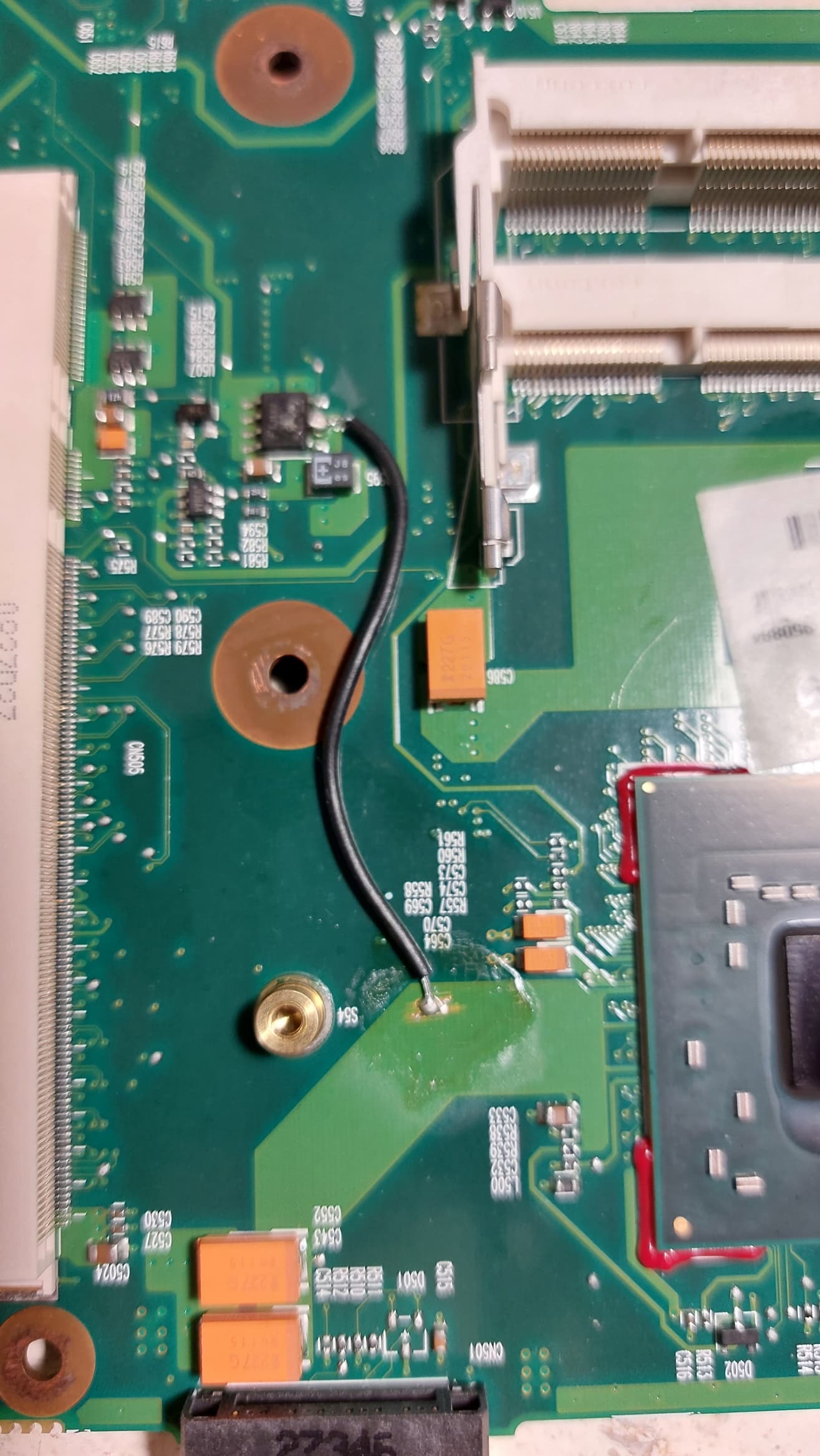
As for your picture, that’s not a minus. That’s VCCP. On both ends of the wire. Maybe the trace from Q516 was damaged somewhere, so the connection was restored with that cable.
I’m not up to date with electronics, it’s only been a few months that I’ve been trying to learn some basics when I have time.
I usually repair visible damage and replace components that are easy to replace. I glue cases, paint, replace parts, improve, upgrade.
My profession has nothing to do with all this!
For several months I have been trying to equip myself with technique and knowledge for more complex repairs.
I’m still far from understanding electronics!
But I’m walking on the road, slowly, but I’m walking!
Today I confirmed the theory of recovery of video cards by heating.
On the Dragon I got a week ago, the graphics card was not working.
I pre-placed flux all around the chip and around the video memory!
I took a heat gun and slowly, over the course of 10 minutes, heated the video card chip to a temperature of 181 degrees Celsius, held for about 30 seconds and stopped.
I used a fine adjustment gun and a simple laser thermometer for instant control!
I didn’t dare to heat anymore for fear of cracks in the chip.
I cooled it down, turned it on and everything is OK for now.
There is a picture, Windows is loading!
I am happy!
Ok, I see. Good luck with your studies, it’s a pretty interesting realm.
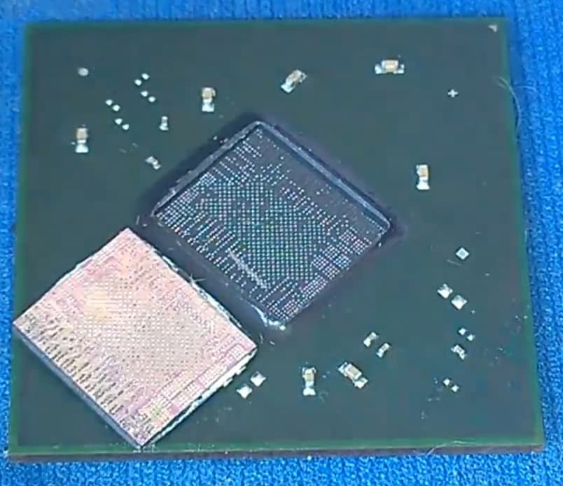
I believe that the problem with video cards is caused by bad connection between the GPU die and its own PCB board which is then soldered onto the motherboard. The compound used for sticking the die to its PCB moves the die in some directions because of constant changes in temperature, higher temperatures expand the compound and then it compresses back after cooling down. I don’t know why CPUs don’t have the same issue though. This is just my understanding of why graphics cards fail.
I had and idea to try to remove the compound around the GPU die and use a heat gun and flux to restore the connection, but that black thing is pretty much strong and I couldn’t remove it,
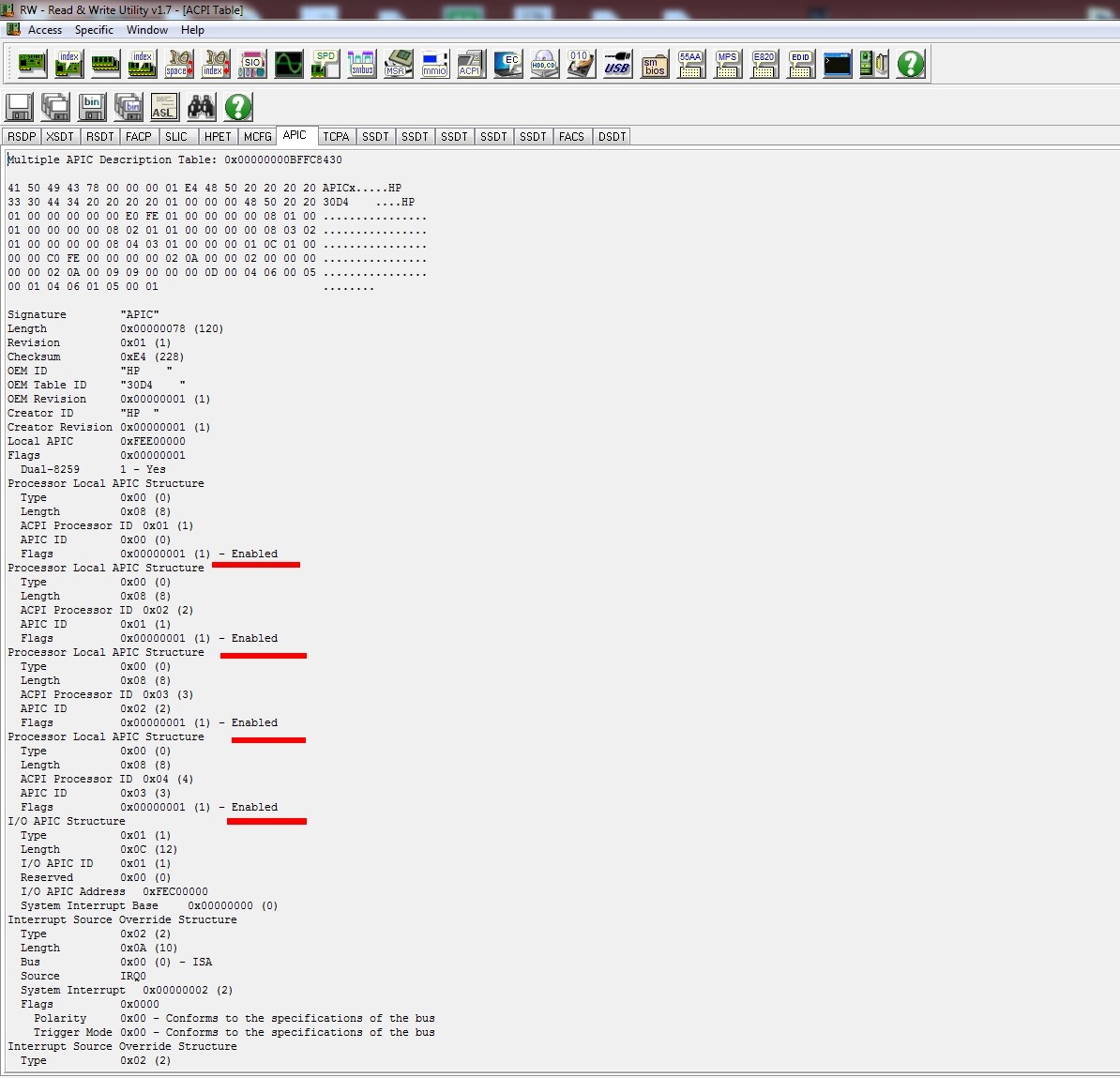
I have just succeeded in replacing the dual core APIC table with a quad core one. It should now be possible to install QX9300 after applying the GTLREF2 mod in the CPU socket.
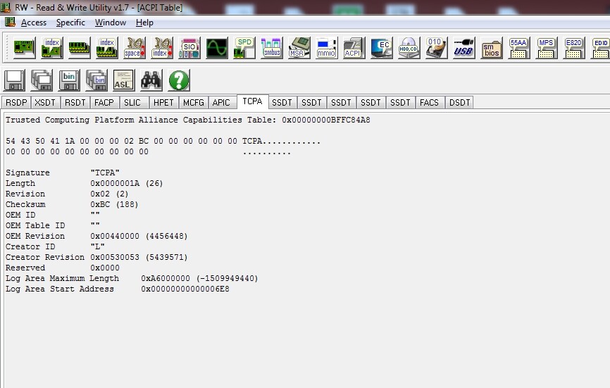
In order to achieve the APIC mod, I need to move the APIC table to the TCPA table and cut the length of the TCPA in its header to 1A which equals to 26 bytes. The rest of the space was filled with 00. Then I removed the zeroed out 16 bytes after the TCPA for the sake of extending the quad core APIC table with those additional 16 bytes.
The TCPA table is used for the TPM device which is the fingerprint sensor, so I suspect that we should not (or will not be able to) use it after flashing the quad core BIOS. In the case of installing a dual core CPU into a normal 4-core laptop, the unused 2 cores in the APIC table are disabled by the BIOS. But since the Dragon is not able to do that, we can probably leave them all enabled even if we keep using a dual core CPU. Just checked myself.
I have also flashed the quad core DSDT and now need to look through some SSDT tables responsible for the CPU power management and see if anything else needs to changed. More updates later.
anyone have bios update for nvidia (8800m gts) version of hdx9000? I have intel x9000 cpu i installed but i want to overclock it which i can’t do without the unlocked bios version. Anyone have it? I tried looking in notebookreview forum archive but the download was replaced with some text about an angry guy who wants you to pay for the bios update download
Yes, I unlocked settings in this one, if this what you mean. But there’s no sense in using it. The bios doesn’t have any overclocking feature.
The version from notebookreview with WL disabled and dual IDA mode is posted somewhere in this thread.
Btw, I recently made a copy of hpunpack. It has more features to it compared to the original. Now it’s open source, and after 20 years you can finally disable bios protection and repack other compaq roms. It was more of a fun project, I don’t expect anyone actively using it. GitHub - Maxinator500/hpunpack-revive
The only problem is that when I try to overclock it, multiplier goes to 14.5 and VID only goes up to 1.25. When I checked on a cpu tool, it said the voltage went up to 1.25 but the multiplier was still at 14. Throttlestop doesn’t even let me increase is from 14.5/12.5
This is why I was guessing the bios locked it down. I am still unable to overclock it
Okay i managed to do 1.3875 VID and 20x multiplier for the max overclock. The problem also was i was using throttlestop version 9 when i should’ve used version 6. Version 6 works just fine with increasing multiplier and VID so that was the problem