I am looking for some help to mod the BIOS of an Intel DG965SS board. I know the board is ancient, but I am asking for help for two reasons. First, I still have this board running WHS 2011 which includes running Plex for my movies and music. Second, I like to tinker with stuff which is how I learn. I have two of these boards so if I blow one up, I am still OK!
My tinkering has resulted in this request for help. I have an E6700 Intel Core 2 Duo 2.66MHz in the server and I recently came across an E7600 Core 2 Duo 3.06MHz for $5 (what a deal!). Little did I realize that the E7600 is not supported by the board’s BIOS. Undeterred, I had heard about adding CPU microcodes to BIOSes so I figured I would give it a try. I figured out how to extract the BIOS and used HxD to look into the file and see where the microcodes are stored. Trying to keep things simple, I did not want to change the size of the BIOS file so I removed just enough of the old microcodes to provide space to add in the microcode I needed for the new CPU. Quite happy with myself, I loaded the new BIOS and the BIOS flash program (iFlash) onto a bootable USB and tried to flash it with no success. I figured that was too easy, so I went looking for answers.
On this website, I could only find 1 reference to my motherboard and it was someone else trying to mod the BIOS for a different CPU (Q6600). There was a fix for that, but that does not help me with my E7600. Are there other changes that I need to make to the BIOS file when updating the microcodes? Do I need to change the BIOS version? Do I need to change/update some other data in the BIOS? Is there a switch that I need to include in the iFLASH command? Unfortunately, the failed flash did not give an explanation as to why it failed.
Thanks for any advice!
Edit by Fernando: Thread title customized
Hi @oldsports
Intel boards from this era are notoriously fickle with bios mods. I would not even attempt an Intel board bios mod without some form of hardware programmer for recovery purposes.
The CH341A would assist, or alternatively, a Flashcat or Raspberry Pi - there are others but that’s where i’d start.
Hi @IntelModder ,
Thanks for the reply. OK - you have intrigued me so I am going to use this as another learning opportunity. I just purchased a CH341A device and I should have it in a couple of days. Can you point me in the right direction so I can try to do the mod on my own? As I said, I have two boards so I am OK if I blow up one.
Thanks!
You were on the right track. In this case:
1) When you get your CH341A make a backup of your current bios (for recovery). A good tip is to dump the bios twice and use a hex editor to compare. They should be the same.
2) Try your microcode hex mod again on a copy of the backup.
3) Re-flash the board using the CH341A and your modded bios.
4) Document where you get to (POST codes if present).
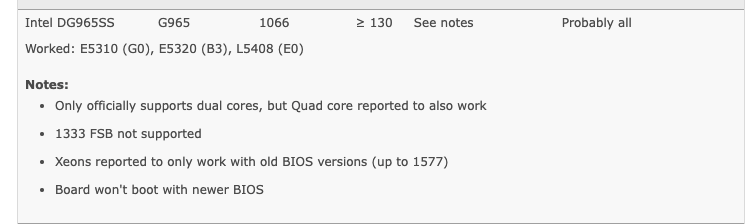
I’ve attached some additional information about your board from the delidded LGA775 to LGA771 guide
@IntelModder ,
Thanks for the information. Once I receive my equipment, I will follow your instructions and report back.
While doing research online after my failed flash attempts, I saw places where folks said they got the Xeon to work. They also said that a couple of the pins had to be modded because the 771 socket is a little different than the 775. Also, on this forum someone reported getting a Quad (Q6600) to work by upgrading the microcode (6F7 or 6FB, depending upon which one you have). The Quad’s run hotter than the Duo’s (95W vs. 65W) which could be a drawback in my old rig. Since I have the E7600, I will try to make it work with that. If I am successful, I might try it with a Quad if I can find one cheap.
More to come.
@IntelModder ,
I am still waiting on my CH341A programmer to arrive. In the meantime, I have been downloading software from the Internet to use with it. There are a number of choices - do you have a recommendation?
As I prepare to do this mod, I have been thinking about a way to help others with what I figure out. As you suggested, I will extract the BIOS from the chip using the programmer, modify it and flash it back. If the extracted data is the “raw” BIOS (versus the specialized .bio file that cannot be easily modified), is it possible to rename the “raw” BIOS file with a .bin extension, make the edits and flash the chip with software used by other BIOS chips (i.e. AWARD, AMI)? Or, is there a Run command switch for iFLASH that would instruct it to flash the raw BIOS file? My thought is that if this can be done, it would be a workaround to needing to use a programmer to load the modded BIOS and it could be more easily shared with others.
I installed my spare DG965SS board into a mid-tower case with a CD-ROM; this is my test rig. I found out that the BIOS recovery process works on the board. While impatiently waiting on my programmer to arrive, I decided to see if I could flash my modded .bio file using the recovery process. My thought was that the recovery process might not make the same file checks as the iFLASH program does and it might load the file as is. I was wrong - the flash was unsuccessful and bricked the board! I was able to flash an un-modded .bio file using the recovery process and the board is operational again. I guess I’ll just have to wait for my programmer after all!
Thanks.
@IntelModder ,
You can ignore my question about trying to make the "raw BIOS" extract from the chip into something that can be flashed by software. After several hours of research, it appears that secret is going to the grave with the Intel folks who created their BIOS package!
I am still interested in your recommendation for programming software, if you have one. Otherwise, I will choose one of the ones I found on the Internet.
My programmer arrived this afternoon. I did not have time to play with it, but I did try to use the clamp to connect to the BIOS chip just to see how it is done. I plan to leave the chip on the motherboard; I do not have the skills to remove and re-solder it. The clamp was more challenging than I imagined, and I am not sure I ever really connected it correctly. I guess the only way I will know is when I try to read the chip. Any pointers on how to connect the clamp?
I read some posts about the best way to power the chip while reading/writing. Some recommendations were to perform the read/write with the motherboard powered up; I also saw some recommendations that said not to do that and to allow the programmer to provide the voltage from the USB port. What is your recommendation? My BIOS chip is an SST25VF080B 1MB SPI Flash, if that makes a difference in the recommendation.
I plan to try reading from the chip sometime tomorrow. I will let you know what I am able to do.
Thanks!
Yes, unfortunately. Hardware programmers are the way to go with Intel boards.
Best bet is Asprogrammer on Github
This one is trial and error. It should have a red wire going to Pin 1 - match that with Pin 1 on the SST25VF080B (usually marked on the flash with an indent).
Don’t ever assume you’ve made good contact! Always verify by dumping and comparing 2 dumps otherwise you could get a bad backup and be unable to restore.
Leave it to the CH341A. My recommendation is to disconnect basically everything from the target board
I want to give a quick update. I found the AsProgrammer software, loaded it on a laptop and installed the CH341A device with no problems. For the last few days, I have been having trouble with the clamp I received with my CH341A. I cannot get it to stay connected to the BIOS chip; I am trying to connect it while still on the motherboard. The clamp just slides off of the chip - I cannot get it to hold on no matter what I do. I found a YouTube video of someone following the same process and their clamp held on the on-board chip without an issue. I am thinking that maybe I have a cheap clamp (the device only cost me $14 US) so maybe I need to find a better clamp.
I know you said that this part is “trial and error”, but do you (or anyone else who have done this) have any advice for me? Could it be the quality of the clamp?
Thanks!
It could be the quality of the clip - but i’ve only ever had that issue with a clip i’ve used too much. Never with a new clip.
If there’s space around the SST25VF080B with no small ICs, press the clip down on the board either side of the flash and gently allow it to close while keeping firm downward pressure on the clip.
Does this motherboard have EFI 1.10 or UEFI 2.0?
The motherboard has EFI (definitely not UEFI). I assume it is 1.10, but how would I know? The motherboard manual describes the BIOS as “Intel® Platform Innovation Framework for extensible firmware interface”.
It’ll be EFI 1.10 - possibly even 32bit. My D955XBX from that same era is 32bit
Thanks for the clarification on the EFI version.
Unfortunately, I am still having no luck with getting the clamp to stay connected to the BIOS chip. I am leaving on a business trip tomorrow, so I will not be able to try again until I return next weekend. If you think of anything that could help in the meantime, let me know.
Thanks!
You can find out by downloading an old EFI Shell, typing ver or from rEFInd Boot Manager.
I returned from my trip and tried again (unsuccessfully) to get the clamp to stay on the chip. I contacted the company from where I bought it to see if I can get some help. One thing I noticed is that the contacts on the clamp are smooth. I assumed that the contacts would have something (i.e. an edge or a point) that would allow them to dig into the chip leads to hold it in place. Should this be the case?
Thanks!
The company that I bought the unit from was no help, but they did offer a refund. I did some more research and found a number of interesting things:
-
When I started reading the reviews on the unit, I found numerous comments about the quality of the clip. A couple of reviewers recommended using a clip from Pomona. The clip costs $25 US which is almost double what I paid for the entire CH341A kit! However, my curiosity has gotten the better of me so I am considering making the investment.
-
Some reviewers also said that the unit only provides 5V versus 3.3V which is needed by some chips. Apparently, some units were made with black circuit boards (what I have) that have this issue and some have green circuit boards that do not have this issue. I even found an old post on this site that discussed this issue. There is a modification that can be done to correct this.
-
On Amazon, one of the sellers of the unit I purchased said the following: “Due to the characteristics of the CH341A chip, the ESMT SST class 25 chip can only be read and cannot be written”. My chip is an SST25VF080B made by Microchip. Are these two different chips or will I have an issue with writing to this chip?
Assuming I am able to write to my chip, I plan to purchase the better clip and make the supply voltage modification on the unit (my chip needs 2.7-3.6V so I don’t want to burn it up). This started out as a $5 US investment for the CPU that is turning into another $40 US investment to get it to work! I am chalking it up as another learning opportunity.
Thanks!
Hey mate @oldsports
You can see how deep the rabbit hole is now. I’ve been using hardware programmers for years now with all sorts of projects.
Mine are in frequent use - I have one of each of CH341A, a Flashcat, & Nano Bios Programmer. Each have their strengths and weaknesses.
My point is that because mine are in frequent use i justify the cost on the basis that i’ll get it returned over the life of the product by using it in multiple projects. In your case, this is really old hardware and we’re after a dump of the chip for the possibility we might be able to make the microcode mod work.
Looking at the expense as a learning opportunity, or a hobby, or if you can use the knowledge elsewhere is a better view. Up to you how you proceed!
-
On the Pomona - i’ve bought and used one before, and yes they are better quality. In the end I go through so many through frequent use, i just buy the cheapest clip that’s closest to me.
-
Some CH341A do suffer this issue. I don’t have any experience with that particular modification.
-
Re the SST25VF080B I’m super frustrated because I had detailed notes in my possession as to my own experience with that chip and a D955XBX from the same era. My SSD with those notes recently died and was replaced under warranty - i didn’t back up the data (more fool me). From what i can remember, I either wrote to it with Asprogrammer and the CH341a OR the Nano Bios Programmer and its software.
Yes, I see how deep the rabbit hole is getting - I am up to my ears in mud! Right now, I feel like I am in the middle of a movie and I want to see the end of it. It could be “happily ever after” or it might be a horror show. The $50 US that I am up to will be worth it as long as I learn something - even if I never program another BIOS chip.
The modification of the CH341A unit looks fairly straightforward. My soldering skills should be good enough to pull it off. This will make the unit a permanent 3.3V chip programmer, but if I ever had the need to program a 5V chip I would purchase another one and leave it un-modded. I will do this while I await my Pomona clip.
Thanks for trying to find the information on the SST25VF080B. I think this is the biggest risk of the project. If It turns out that I cannot write to it, the work will be mostly for naught. At a minimum, I can give you some of the information you lost about the BIOS chip when your SSD crashed.
While I was being frustrated with the clip issue, I perused through eBay and found three used Q6700 chips for $32 US total delivered. I recalled the post where a person was able to get a Q6600 chip working. As it turns out, my BIOS version already had the right microcode for the Q6700, and the post included a modded version of the CHECKUP7 program that upgraded my microcode to the latest version. I first installed it on my test rig and then on my WHS 2011 server with success. I used a hardware monitor program to verify that the microcode version was updated and I checked the core temperatures since the Q6700 is a 95W chip and the original E6700 is a 65W chip. The cores are averaging 38-40 degrees C; according to cpu-world.com the upper limit is 71 degrees C so it should be OK. I did not improve on single-threading since both chips are 2.67 GHz, but it should drastically improve any multi-threading by doubling the cores. Worst case, if I never get the E7600 working, I have made some improvement.
I will update you once the Pomona clip arrives and I have a chance to play with it.
Thanks!