[Request] Tronsmart Celeron J1900 AMI BIOS

MiniPC link

Can anyone please review my miniPC ROM & provide answer to one small question: Is this BIOS supports auto start on power failure (or this feature can be added) .rom on mediafire

I have investigated I can find reference in 'BIOS Strings` tab as indicated in pictures

If this feature is not available I will hardwire some relay to switch it on automatically when power returns after failure. BIOS modding seems much lucrative option here

In the attachment I have mentioned some features that are mentioned but not visible in BIOS:


AFUWIN_BIOS

Hi @ioncube, the file at mediafire seems to be faulty (I could not open it although I am using the same software version). According to your images, your BIOS/UEFI seems to support automatic boot after a power failure.

You can change the visibility of entries in the BIOS/UEFI using the “Setup Configuration” menu in AMIBCP by modifying “Access/Use” (select “Supervisor” instead of “Default”).

@vega extremely thanks for replying. Please bear with me x1 day more. I will upload .rom again. Its weird the file is not opening because I used version 3.xx to make it

No worries I will remake & reupload. Ok included is the .rom + afuwin afuwin_+_rom.7z

Secondly you said Supervisor mode instead of User mode which i read in many online tutorials? Please elaborate

@ioncube, I have looked at the new file, the strings “Restore AC Power Loss” and “Select AC power state when power is re-applied after a power failure” unfortunately do not lead to any setting. It seems that they are sort of relics in your BIOS/UEFI file. :sob:

But you can still try something. Perhaps there is a newer (or older) version of this BIOS/UEFI. You could take a look to see if there is an option to activate an automatic boot. Sometimes there is also a “Power on by RTC” feature that you might be able to use (I couldn’t find it in the file you uploaded, but maybe it exists in another version).

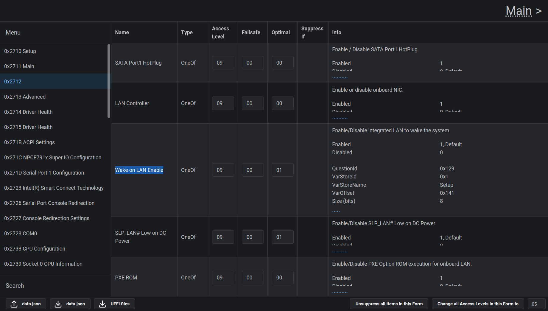
In your file I could at least find an entry for “Wake on LAN”, perhaps this is useful (in addition to AMIBCP, I used this tool):


About the “Supervisor” thing in AMIBCP, I had changed this value to “Supervisor” when I modified my BIOS/UEFI and it worked (I had seen this in a modified file from someone else the first time I used AMIBCP and adopted it). If you have found “User” as a recommended value in tutorials, you can select “User”, it will most likely work.

In case you consider a hardware solution, a NE555 (a very common timer IC) might be helpful. You can use it to generate a delayed single pulse after power is applied (equivalent to pressing the power button). There is an article about this on StackExchange.

1 Like

@vega extremely thanks for your reply & time

First i want to tell you that I wanted to work on a hardware solution provided that I have x2 RADXA 3E up & running 24/7 & using GPIO + a simple bash I can directly send pulse signal to switch on miniPC. The problem I am encountering is I cannot find trigger terminals on the motherboard. I have discussed it in details here with pictures

Per this comment I tried jumper on these terminals but machine didn’t start

I can tell you that while machine is running (initiated via touch sensor) I am getting following voltages

Regarding modding of BIOS I will report back, however, I must tell you WOL feature is always unreliable

@ioncube, thanks for the explanation, now I have a better idea of what hardware is used.

I assume that the touch buttons are processed on the same small circuit board, which would mean that digital signals are used on the connector (as with a physical switch). Can you perhaps check (an oscilloscope would be ideal, but a multimeter may also works) whether the voltage on the individual lines of the connector changes as soon as you press the touch button?

If I see it correctly, Radxa (ZERO?) 3E would be a single-board computer, comparable to a Raspberry Pi. You should be careful because the GPIO pins use a 3.3 volt level (and can tolerate a maximum of 3.6 volts). It may be useful for experimenting, but if you only want to switch the device on automatically, I would rather recommend an NE555 for permanent use because it is 20 to 80 times cheaper than a Radxa ZERO 3E, can handle a 5.0 volt signal level and is more reliable (simply because it is much less complex, an NE555 does not run an operating system that needs to run a script to set a GPIO pin).

1 Like

Dear @vega following are my findings

I assume that the touch buttons are processed on the same small circuit board, which would mean that digital signals are used on the connector (as with a physical switch). Can you perhaps check (an oscilloscope would be ideal, but a multimeter may also works) whether the voltage on the individual lines of the connector changes as soon as you press the touch button?


^ When touch sensor initiates or machine powers up

I would rather recommend an NE555 for permanent use
You are correct but first I need proper terminals identification

See the reddit image
I tried shorting blue / white terminals (x2 pairs) but it didn’t work. The JST SH 1.0mm connectors are so small that I cannot use voltmeter on its jack (at motherboard). Any suggestions?

@vega Can you modify .rom & enable WOL feature? I will flash my BIOS & lets try that route. It seems you have experience in BIOS modding but for me its 1st time. Better you than me. Thanks in advance.

@ioncube, I have seen the voltage values. The touch buttons most likely work capacitively, so bridging both terminals at this point will not work. My recommendation would be to observe the voltages at the connector (I assume that digital signals are used there).

This means that you connect the negative pole of your measuring device to a part that is connected to GND (e.g. the metal housing of a USB port). With the positive pole of your measuring device, you can measure the voltage at each pin of the connector.

When you find a pin that changes for example from 0 volts to 5 volts while you press the touch button, this would be the pin that you can use to switch on the computer. The measured voltages will tell you which other one you need to connect it to.

Bridging the blue and white cable is only one possibility. It is also possible that for example, red and white would be the right combination. By measuring the voltages at the connector, you can find out the right combination.

You may be able to improvise with a needle (normally used for sewing). You can either use it to probe the exposed pins that I have marked or, on the opposite side, try to reach the crimp contacts inside the connector with the needle.


Regarding the modification of the BIOS/UEFI, I have done one mod so far. :sweat_smile:

If you are absolutely sure that you can restore the BIOS/UEFI to its current state (in case something goes wrong), you can try the following change using AMIBCP:

I changed these options to “Enabled”. If you have flashed the modified BIOS/UEFI, you can then select “Load optimized defaults” (so that the previously saved state, presumably “Disabled”, is updated) and Wake on LAN should be enabled.

Alternatively, you can try to make the option visible by changing “Access/Use” to “User” or “Supervisor”. The setting for WOL may then appear in “Main” or one level below. But I am not sure if it works because of the subfolder.

1 Like