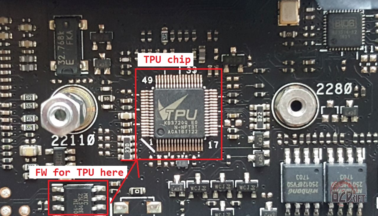
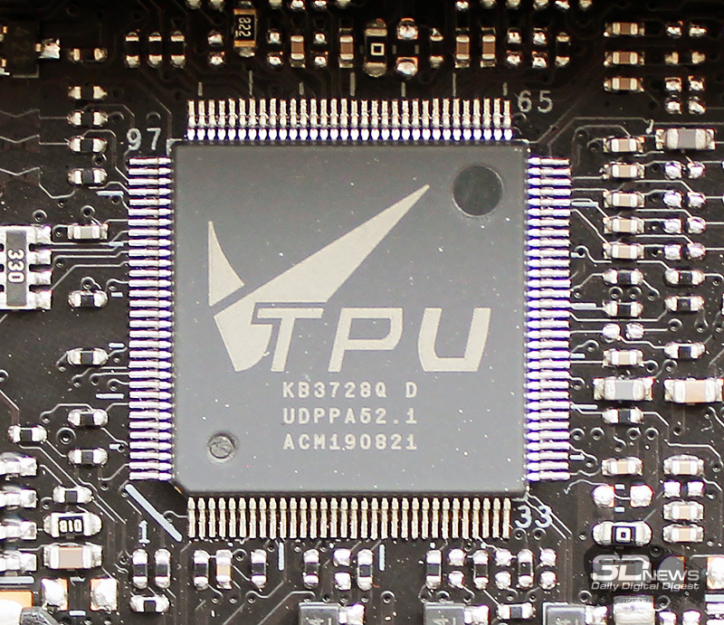
Hi, does anybody know what firmware is stored inside the TPU chip ? - Possible which GUID does it have in bios ?
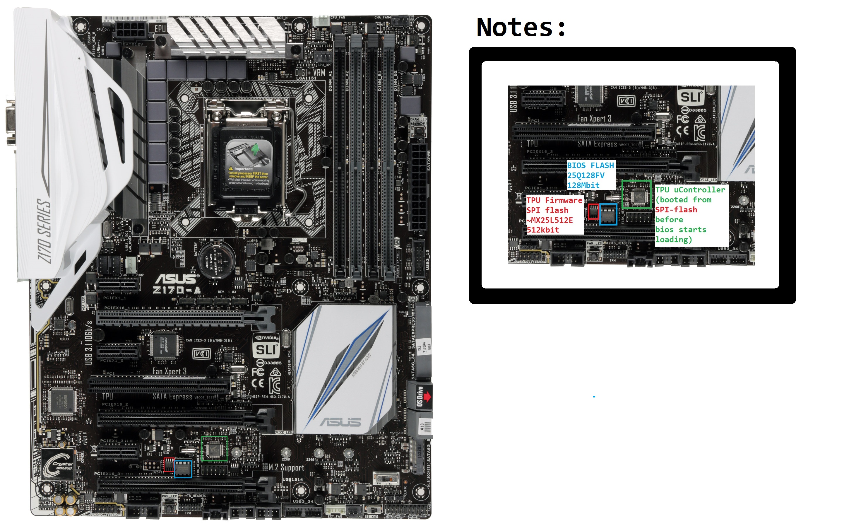
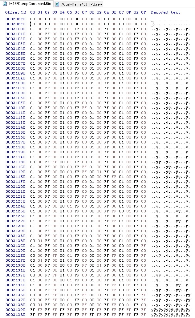
The MX25L512E chips is 512kbit of data (64kB ~ 0x10000) and if it is cleared the board does not boot at all, does not even start the VRM. Board at question for now is [ASUS Z170 PRO].
hard and not guaranteed way to find: - dump bios region of running pc - change some in bios setting regarding this chip (sorry, i dont have much info) - dump again bios region - compare NVRAM partitions of both dumps, there may be many diff/duplicate, get names of nvram containers with diff contents - text search in all modules for each of nvram names in ascii/utf8/utf16 mode finally you will get list of guid/modules who access these nvram containers and probably do magic with this chip
if nvram container is named "Setup", this is bad luck, most modules need access to this contaner
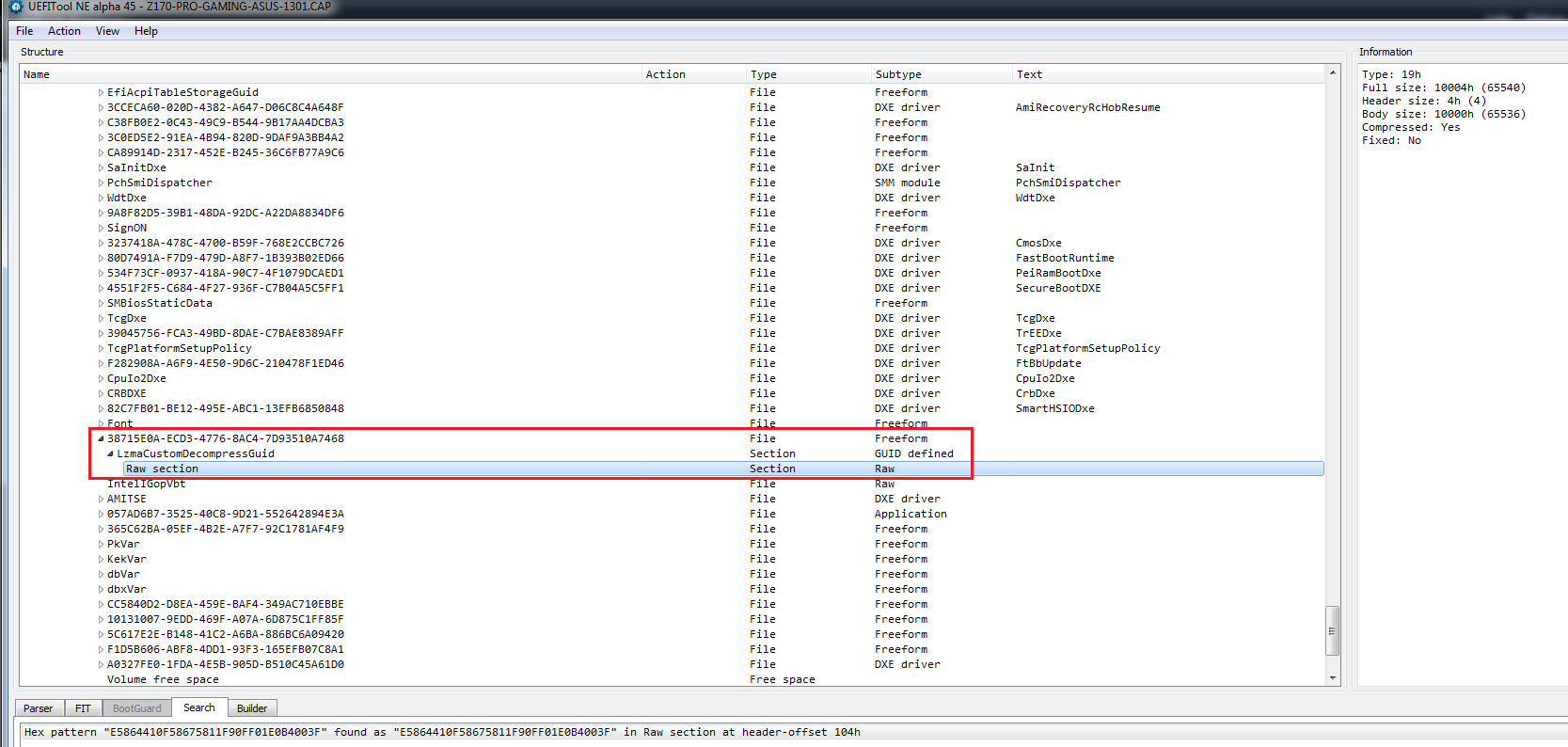
I found the TPU firmware module. Thanks @Mov_AX_0xDEAD for tips. GUID for tested ASUS boards is: 38715E0A_ECD3_4776_8AC4_7D93510A7468 #edit: (tested-board="ASUS Z170-PRO")
What and why, possibly how: What is TPU unit? Q1) Almost all Z*70 ASUS boards have this. The TPU module. It is supposed to enable auto-overclocking etc. More info on asus web or forums. (that to be said based on asus marketing of this chip) — What i did? Q2) I tried flashing bios with version suggested to enable BCLK overclocking. I did this by flashing the bios memory chip directly. Booted and short notification of "bios upgrade" showed on my screen, after that the board shutdown. I could not get it boot again, not even to light up any led on board etc. — Why bios re-flash "back" to original version does not work? Q3) IMPORTANT! TPU module starts even before the bios starts loading. Is is enabled in stand-by mode - even before user presses the power button. .
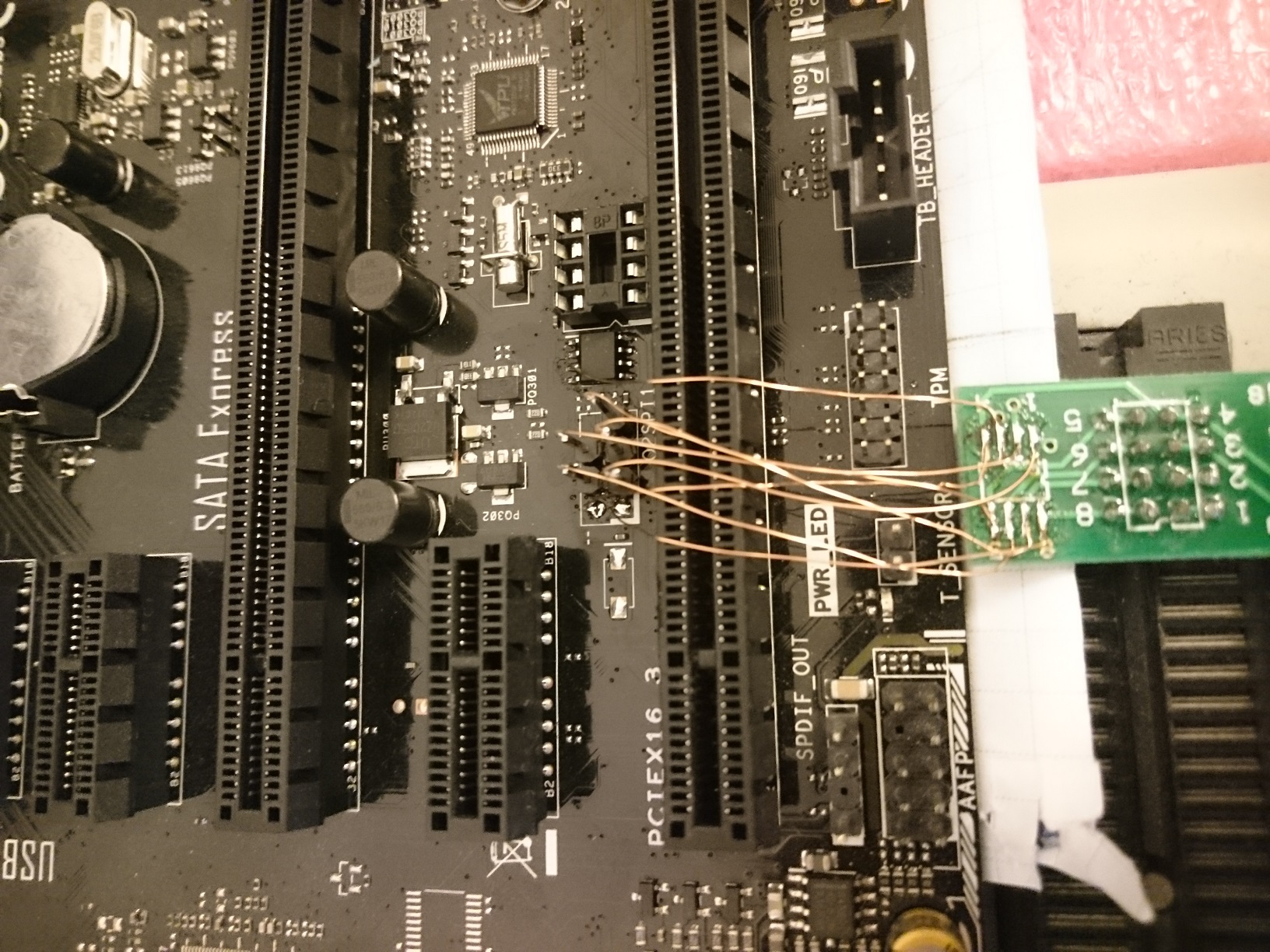
Without TPU working correctly (or at least partially correct) the board does not start. It has some conections to power enable and it holds the whole board in "reset" state. Also it ties to the LPC bus and chipset boot sequence. Bios reflash or rollback does not help the situation because this bios does not even start loading to PCH so it can not re-flash this chip back. — How did i find GUID and flashed the TPU firmware back to original version? Q4) The MX25L512E memory in this case is routed directly on board. I connected my digital analyzer and reverse-engineered the pinout on board. I read the memory and used this data to find original raw data in bios flash under mentioned GUID. Using the same GUID i found the TPU FW in old bios for this board. De-soldered, programmed and re-soldered the memory to board. (While soldered on board the write-protect is brute-forced being tied to power-lane.) After i flashed correct version of TPU-FW to the MX25L512E and soldered it back with old bios being in the bios-flash memory, the board STARTS NORMALY.
Conclusion: A1) TPU FW has a lot to say in board boot and power-on sequence. A2) Flashing wrong bios (eg. ASUS z170-pro gaming, instead of ASUS z170-pro ) can and most likely will result in bricked board. A3) Board can be resurected from this, but it requires re/de soldering the TPU FW memory. Also, TPU-FW GUID might differ between boards production generations.
Hi LittleHill, I just want to thank you for your’s instructions. I repaired the motherboard (ASUS P8P67) from the my wife’s computer. It had a very strange problem. Every time to power on, first the mains should be removed. At one moment it stopped to power on completely. I thought that this may be related to the TPU. Desoldered the flash, read it and compared it to the FW extracted from the BIOS (the GUID/module with 65536 bytes size). There was no difference, but I reflashed it, just for any case. Soldered it back and for for my surprise the motherboard came back to life.
People do not seek easy ways))) just had to initially remove the GUID for TPU firmware. in the end for this controller will not automatically update the firmware. Just first you need to learn, what controllers on the board and what kind of firmware are responsible for them. it’s simple obvious things. Did not need anything to solder, it’s stupidity. to restore it was enough to replace the firmware in GUID with the correct version, the system would automatically update it. when enabled, the BIOS makes a reconciliation of the versions each time.
First, the firmware version wasn’t wrong, please read my post (probably it was flash malfunction). Second, how the bios will update the version, when the board doesn’t power up at all?
I understand what you are saying, however this was related to the coffee-lake mod research and i needed to have a thread which i can refer to in order to explain issue when updating bios after switching id to sku of z370 and recompiling for coffee lake mod. It can obviously be approached in different way, however as i made the mistake not knowing about tpu automatic upgrade it bricked my board.
Mentioned above, if you somehow end up in this state, any changes in the bios flash do not help. If you are able to determinate the uC core and reprogramm the flash of tpu via TPU programming pins, guss that works too. For me it was much easier to de-solder and determinate if tpu is the actual issue. It was.
Have looked some more into this and on many ASUS boards e.g. Maximus 8 Impact, there are more TPU style modules, each with their own firmware version as visible in the bios, called iROG# modules. Below the respective GUID’s:
iROG1: GUID 38715E0A-ECD3-4776-8AC4-7D93510A7468 - as mentioned by LittleHill iROG2: GUID 475EB5AF-16F2-4727-BD69-0D1BF383196C iROG3: DE9A07DF-B1C6-448B-B700-715F6BE6676D - this one seems to be responsible for the KEYBOT feature
The GUIDs are the same across all ASUS boards. Might be an idea to take this into account and delete these GUIDs in donor bios or replace with Z170 / Z270 ones to avoid bricking anything.
@jxaker We can easy find TPU module in main bios by keyword PWRBTN. Next time, with UEFItool extract body and we have 65,535 dump for programming another flash chip.
So someone please explain how to find the tpu firmware in the bios step by step. I couldn’t realy processit by just reading this thred for an hour i tried what is writen here but i probably didn’t do it right.