Dear all,
I have an sp4 which is getting no screen on at power on, despite the systems is alive ( windows sound and keyboard backlight)
Ive studied bunch of thread here around and are all really enlightening especially the post of @Lost_N_BIOS
As the above described issues has happened after a bios / uefi update, thus my suspect goes to a faulty update process.
Now I’ve purchased the ch341a black/gold edition.
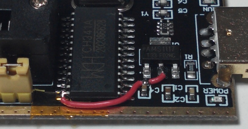
I’ve done the mod to it to ensure I have voltage capped to 3.3v. ( lift one pin and short it to the regulator)
Ive removed the w25q128fv bios chip from the board and soldered it onto my dummy board supplied with the programmer.
Ran 1.34 software and extracted the dump.
Verified it successfully.
Now before to go any further my questions are:
Is there a way to read the bin and try to find out if the dump is consistent?
The ASCII on the right and side have some weird carter sometimes and not all is formatted and this scares me a little bit.
Also I didn’t try to dump before doing the ch341aod to 3.3v and I’m also unsure if what I’m reading from dump is proper or can differ due to this mod?
What are the tools to diagnose and look at a more structure manner at the dump once extracted?
I’d like to see if there are link to the serial number of the sp4 or other things that can confirm that my dump is ok .
Thank you for your feedback.
Well this thread is in the Management Engine section for some reason so I assume you want to check if the CSME firmware is healthy. In that case, use ME Analyzer with -unp86 -bug86 parameters. You can generally check the structure/validity of your dump via UEFITool NE.
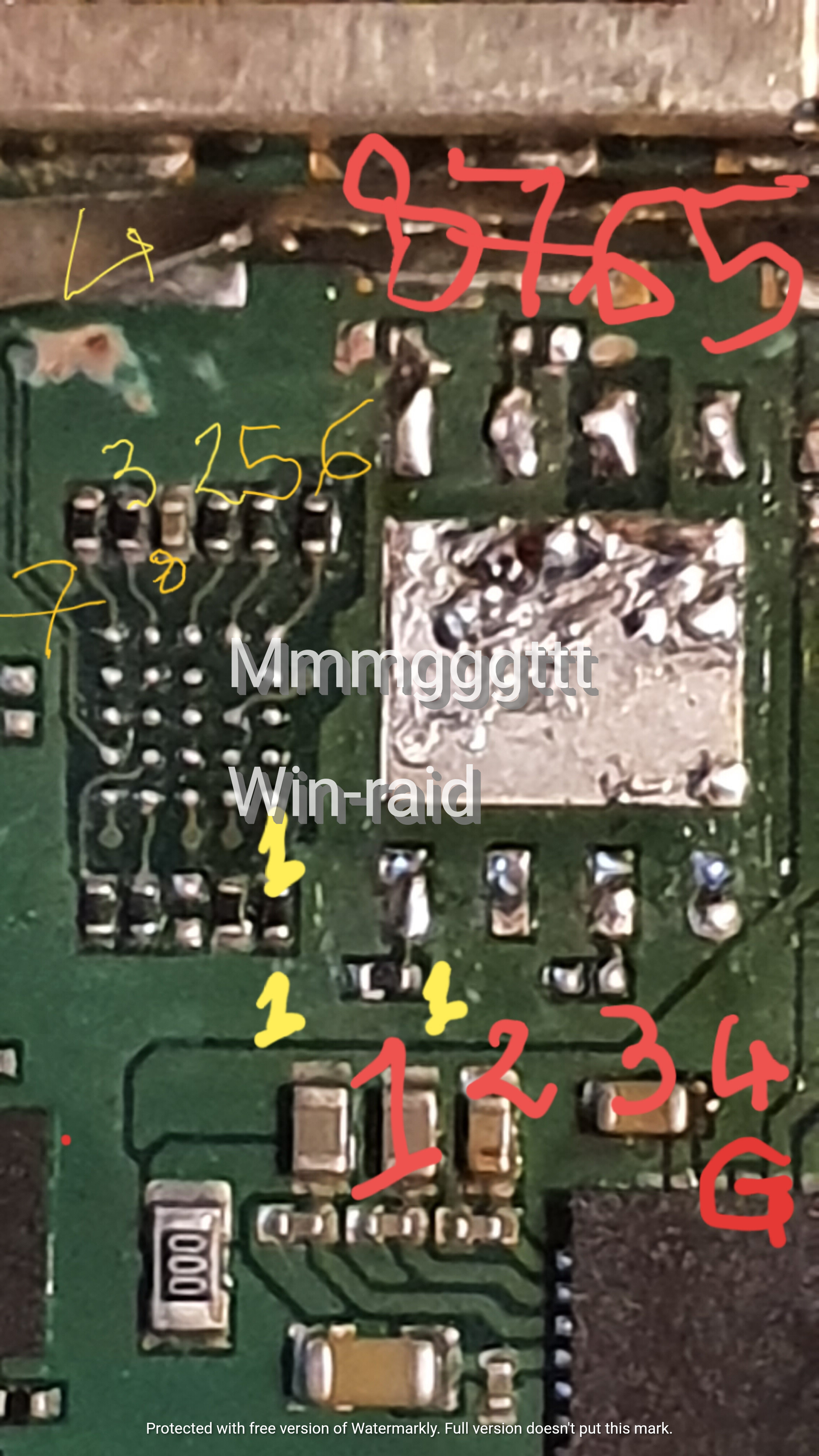
I will give it a try. Let me give an head up (still to be tested) for alternative point to solder to possibly avoid to dismantle the chip.
All points are measured <0.2 ohm
Should work not tested yet thou

@Mmmgggttt - You can compare dump via hex to see if they match, then at least you know the dumps match, but this does not verify the contents are not badly dumped.
It could be bad dump still, yet still pass verify after read due to software or version incompatible with chip.
For W25Q128FV you need to use 1.18 version CH341A software (for valid read only), or use ASProgrammer 1.41, otherwise other versions always fail (at read sometimes, but write always).
Here is CH341A software package that has 1.18 - http://s000.tinyupload.com/index.php?fil…213094641136166
And here is ASProgrammer 1.41 - https://github.com/nofeletru/UsbAsp-flash/releases/
For write to this chip, only Colibri (included below) or ASProgrammer has been confirmed working here by others
The version inside this folder may work as well, for read or write, unsure and untested >> CH341A v1.31(1.4) (CH341AFree)
Also, you can probably look at the BIOS in UEFITool once dumped, if it’s similar to other Surface Pro 4 BIOS I’ve worked with (not all are same)
Hello @Lost_N_BIOS and many thanks.
What do you think about having modified the programmer to stabilize it to 3.3v?
Could this potentially impact the quality of the dump content ?
See attached pic (pin 28 from 1117 IC is lifted and shorted to C4 and regulator)
I took the guidance for this mod on another forum (not sure o can post the link to the thread).
Thanks

@Mmmgggttt - You’re welcome! The mod is not unnecessary, aside from that I don’t have any experience with it personally.
Voltage out at the slot pins is always 3.3v range, unless you get a defective unit, so you don’t need to do the mod, but it should not hurt anything.
You can post links here, but I don’t need to see, already am familiar with it and would prefer not seeing it linked more (fearmongering and it spreads concerns for no reason)
Dump BIOS using the tools/versions I mentioend above, then compare, whatever does not match 1.18 read is not good
And then only use Colibri to write, if that fails (confirmed by dumping after writing, without powering on system, then hex compare with what you wrote), try ASProgrammer to write instead.
@Lost_N_BIOS not sure I could not find colibrì link in your previous post?
So what you are saying is that mod to cap to 3.3v on black/gold devices is not needed even when try to read from board (other components risk to be exposed to higher voltages? ) And I’m referring especially to w25q128fv
Thank you
Sorry for not being clear there, it’s in the package I linked for 1.18 version, lots of CH341A software in there
Yes, that’s exactly what I mean. Buy another one and then you can check with DMM in the socket pins while reading or writing, it only uses 5V internally, out to the BIOS socket is 3.3V
I just got a good news from the supplier of a very old programmer I had (actually at that time I think that was the one and only not professional one to operate on usb after beloved serial multipipo) that it now supports w25q128. In his latest beta version software
It is silancode’s zp20e and it has the 3.3v and 5v mode selectable by jumper.
I’m curious to compare the two dumps from the two programmers and I have full trust in this programmer.
I will also test my alternate pin connection in post #3 ,I’m quite sure that the island shown in picture is there for the use of a proper connector to load bios update directly on the surfaces assembly line at bench
I’ll get back to you !
@plutomaniac I have run the ME analyzer with the option you’ve mentioned.
The result can be found here
https://pastebin.com/DUAuwVCT
can you give it a check?
Also I’ve used my zp20e (which tooked almost three times the time to read the chip) and compared the output bin of the CH341A. I can confirm both dump are equal.
BR.
I think it’s ok as I’m not getting any "error" or "invalid" string matches at the output log of MEA -unp86. If you run it with "-unp86 -bug86" and it does not stop at any error or similar, then the CSME firmware is probably healthy.