Z390 AORUS PRO WIFI microcode mod

@t0rcke At what frequency?

Here is a quick screenshot of tref maxed (65534) @ 3900 MHz using 4 x 8GB DIMMS (32 GB) on BIOS F12:

Before I could run max without any issue, however now I’m struggling, but I think its just a temp issue. I just wanted to double check here to see if it’s a problem with the board; thank you.

1 Like

Reviving this topic since I have delved into this stuff recently. I want to update my BIOS to support Resizable-BAR. While this is possible to do using ReBarUEFI on my current version, F9, I figure it is just less of a hassle to update to the version which supports it. This is available on the F12k version, which doesn’t have a capsule, however, if there is no performance loss to just update to the newest version, F12, I see no reason to not due so, since it is possible to downgrade using your guide if I really wanted to. I’m also willing to re-overclock my RAM if I have to. I would first like to know: if I do this, would there still be a point to modify the F12 BIOS to include the oldest microcode? I would expect all the security fixes/patches to already affect performance to the point where just using the default microcode wouldn’t make a difference.

Also, I have followed the first part of your guide, in case I want to downgrade once I flash to the newest BIOS, and I have run into a problem: I can’t seem to find my MAC address in the GbE export ( fptw64 -gbe -d gbe.bin). I know I can save the MAC address using another method, but I’m just wondering why it doesn’t show up in there. Also, does fptw64 -d bios.bin save the entire chip, or just the BIOS/UEFI region? If so, isn’t the GbE export command redundant? I saw a comment on here that says you need to unlock the flash descriptor, so I assume the answer is no, but I still wonder if it saves other parts.

Another thing I want to ask is if it is possible to downgrade using a programmer? Common ones recommended here are the CH341A-based programmers, but I’ve heard they possibly cannot deal with .cap files. I’ve also heard that using clips to clamp onto the chip is dubious and that flashing in-circuit can cause problems, but I’m not sure how accurate these claims are, so hopefully you can address them (8:03 - 9:13).

Edit: Where is a good place to get one of these programmers? The ones I find are either the old versions, or take a while to deliver. Are there any alternatives?

@t0rcke

I would first like to know: if I do this, would there still be a point to modify the F12 BIOS to include the oldest microcode? I would expect all the security fixes/patches to already affect performance to the point where just using the default microcode wouldn’t make a difference.

If you use Windows 10 then the microcodes will be ‘updated’ to:

906EA = B4
906EB = B4
906EC = AE
906ED = Not included in mcupdate_GenuineIntel.dll - so whatever is in the BIOS

If you use Windows 11 then the the microcodes will be ‘updated’ to:

906EA = DE
906EB = DE
906EC = DE
906ED = DE

That is unless you rename/delete mcupdate_GenuineIntel.dll (note that you can’t do this with Windows 11 insider preview Beta channel, it will cause a repair boot looop).

So you need to decide if messing with the mcupdate_GenuineIntel.dll file is worth your time, as it often gets restored with Windows updates (or if you run the system file checker e.g. sfc /scannow).

I can’t seem to find my MAC address in the GbE export ( fptw64 -gbe -d gbe.bin). I know I can save the MAC address using another method, but I’m just wondering why it doesn’t show up in there.

If you open the gbe.bin in a hex editor, look at offsets 0-5, it should be right at the start of the file for the Intel I219-V 1 GbE adapter.

It should start with 18C04D for ‘GIGA-BYTE TECHNOLOGY CO.,LTD.’

Also, does fptw64 -d bios.bin save the entire chip, or just the BIOS/UEFI region? If so, isn’t the GbE export command redundant?

The entire SPI Chip will be dumped.

You are indeed correct it is compeletely unneccessary but - Why search a entire BIOS file for your MAC address when it can be found easily in the gbe dump? It is just for convenience.

I saw a on here that says you need to unlock the flash descriptor, so I assume the answer is no, but I still wonder if it saves other parts.

Gigabyte did not lock the FD down on Z390 BIOS so no issues there.

Another thing I want to ask is if it is possible to downgrade using a programmer? Common ones recommended here are the CH341A-based programmers, but I’ve they possibly cannot deal with .cap files. I’ve also heard that using clips to clamp onto the chip is dubious and that flashing in-circuit can cause problems, but I’m not sure how accurate these claims are, so hopefully you can address them.

You can use a programmer with any of the Gigabyte BIOS, capsule or not.

Gigabyte capsule is different from Asus (which have a file size difference when i.e. 2KB larger when encapsulated).

The Asus Capsule header should be removed when flashing with programmers or general software flashers such as Intel FPT, flashrom etc.

Where is a good place to get one of these programmers? The ones I find are either the old versions, or take a while to deliver. Are there any alternatives?

Cheap ones? Ebay.

Professional ones that get regular software updates for newer EEPROMs (such as the SOFi SP8-F) you can buy online from any reputable seller (in my country there are only a handful so I can’t really help you there).

That is unless you rename/delete mcupdate_GenuineIntel.dll (note that you can’t do this with Windows 11 insider preview Beta channel, it will cause a repair boot looop).

So you need to decide if messing with the mcupdate_GenuineIntel.dll file is worth your time, as it often gets restored with Windows updates (or if you run the system file checker e.g. sfc /scannow).

So just to be clear, there are software and firmware microcodes, and the software ones take precedence? Would this change be reflected in HWiNFO? I don’t think the .dll will be a problem since I follow this guide which disables updates anyway. So as long it improves performance I’m fine with it. Is there a guide on this forum specifically for changing Gigabyte BIOS microcodes? I’m also curious where you found the specific information regarding the CPUID and OS versions and their respective microcode versions.

It should start with 18C04D for ‘GIGA-BYTE TECHNOLOGY CO.,LTD.’

Ah, ok, I see it. However, the decoded text doesn’t display GIGA-BYTE TECHNOLOGY CO.,LTD. for some reason:

decoded

You can use a programmer with any of the Gigabyte BIOS, capsule or not.

Alright. I know the older versions of the CH431A have a notorious flaw where the data lines are 5V which is too much for most chips, however this can be fixed with a mod. As long as the voltage is correct, there is no risk of damaging the board by using a clip instead of de soldering the chip?

@t0rcke

So just to be clear, there are software and firmware microcodes, and the software ones take precedence?

Correct, Windows will only override the BIOS microcode with a ‘newer’ (i.e. higher number) version.

Would this change be reflected in HWiNFO?

Yes and AIDA64.

Is there a guide on this forum specifically for changing Gigabyte BIOS microcodes?

Not specifically for Gigabyte but the process is generally the same for Aptio V BIOS.

You can use UBU to do this by modifying the file ‘MCUpdate.txt’ found in:

X:\UBU_v1_79_17\Files\intel\mCode

For example, this is how the original file looks for socket 1155v2:

#LGA1151v2
906ED 1151v2\cpu906ED_plat22_ver000000EA_2021-01-05_PRD_B05D764E.bin
906EC 1151v2\cpu906EC_plat22_ver000000EA_2021-01-05_PRD_8F16A419.bin
906EB 1151v2\cpu906EB_plat02_ver000000EA_2021-01-05_PRD_311405CC.bin
906EA 1151v2\cpu906EA_plat22_ver000000EA_2021-01-05_PRD_AB6894CF.bin

You can download the microcodes you want from this thread and copy their names into the text file, like this:

#LGA1151v2
906ED 1151v2\cpu906ED_plat22_ver000000AA_2018-11-29_PRD_05A0A797.bin
906EC 1151v2\cpu906EC_plat22_ver00000084_2018-02-19_PRD_F3514131.bin
906EB 1151v2\cpu906EB_plat02_ver00000072_2017-09-20_PRD_A08C2841.bin
906EA 1151v2\cpu906EA_plat22_ver00000070_2017-08-23_PRD_711B866C.bin

Then you must copy each microcode binary that you have changed in the text file to the corresponding folder in UBU, found at:

X:\UBU_v1_79_17\Files\intel\mCode\1151v2

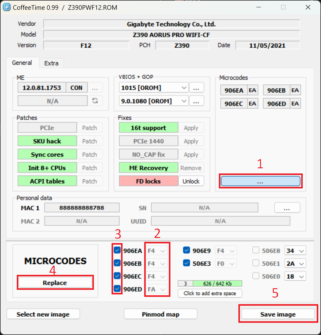
You can also do this with CoffeeTime v0.99 (which has a nice GUI) by copying the microcodes you want into the custom folder found at:

X:\CoffeeTime_0.99\data\custom

Then open the F12 BIOS file and click on each area in order of the number in the image below:

I’m also curious where you found the specific information regarding the CPUID and OS versions and their respective microcode versions.

Plutomaniac (Win-raid admin) has a Github under the name platomav where he maintains an application called MCExtractor that can be used to extract the microcodes from various BIOS files and also the Windows file ‘mcupdate_GenuineIntel.dll’.

However, the decoded text doesn’t display GIGA-BYTE TECHNOLOGY CO.,LTD. for some reason

That is correct, you won’t see that in the hex editor, however you can look up the 24-bit vendor ID on various sites such as https://macvendors.com/ (e.g. try typing 18C04D into that site and hit enter).

Each OEM/vendor generally has a set of ID’s that they use, it is explained well here:

A MAC address is made up of 48 bits. And those 48 bits, they're divided into two different groupings, 24 bits each. The first 24 bits, those are unique to the specific manufacturer or vendor. Those bits are called the OUI, or organizationally unique identifier. The OUI is also commonly referred to as the vendor code.

Alright. I know the older versions of the CH431A have a notorious flaw where the data lines are 5V which is too much for most chips, however this can be fixed with a mod.

Yes, the black PCB versions of the CH431A have been known to supply 5V instead of 3.3V IIRC.

As long as the voltage is correct, there is no risk of damaging the board by using a clip instead of de soldering the chip?

Damaging the board - No, damaging the clip yes :rofl: but seriously - take care with the clip as you only get so many uses out of them and they wear down quickly with repeated use (or worse break if they get violently ripped off), so treat it with care.

Thank you. I did this and will attach the file below; just want to make sure I didn’t mess anything up. I had to modify both 906ED and 906EA since the tool wouldn’t change the microcodes if I just modified 906ED. You mentioned earlier that Gigabyte didn’t lock the FD on Z390, but I see in the tool it states it is locked. Is this only for this particular BIOS version?

Z390APRW_F12_AA.zip (6.8 MB)

1 Like

Thank you.

You are very welcome.

I did this and will attach the file below; just want to make sure I didn’t mess anything up.

Looks good to go, note that you can’t use Q-flash to flash the modified BIOS and will need to use EFIflash from a bootable USB stick.

I had to modify both 906ED and 906EA since the tool wouldn’t change the microcodes if I just modified 906ED.

I have never changed just one microcode - good to know.

You mentioned earlier that Gigabyte didn’t lock the FD on Z390, but I see in the tool it states it is locked. Is this only for this particular BIOS version?

The bit may be set but the protection was not enabled when the BIOS was created.

You can always set it to unlocked with CoffeeTime if it visually annoys you.

Alright, will look at that guide later. I also backed up my BIOS again today and the file hash differs from the one I backed up two weeks ago. I don’t remember changing any settings in the BIOS, so I’m not sure why it’s different. Any theories? Also, have you ever used the “Save BIOS” option in Q-Flash? I don’t think it’s in newer versions of the BIOS, but I also used that option and the file hash for that dump is different than both the files. I assume this option saves different regions of the chip though, but I can’t find any information about this function online. I plan on using a programmer to dump my BIOS as well to compare that, but I don’t have it yet.

I also wanted to ask this earlier, but what does the “x.x” refer to here? I see in your image you sent it’s “Default string.” I think this might have been changed in F9 BIOS you made for me, but I’m not sure:

image

Regarding the MAC address stuff, I found this guide which apparently shows you can change it. How is this possible?

@t0rcke

I also backed up my BIOS again today and the file hash differs from the one I backed up two weeks ago. I don’t remember changing any settings in the BIOS, so I’m not sure why it’s different. Any theories?

Different values being stored in NVRAM is the most likely explanation. Some values are likely changing on each boot.

Also, have you ever used the “Save BIOS” option in Q-Flash? I don’t think it’s in newer versions of the BIOS, but I also used that option and the file hash for that dump is different than both the files. I assume this option saves different regions of the chip though, but I can’t find any information about this function online.

Yes on my Z170. If it has included your NVRAM configuration then it will have different hashes than than the stock BIOS.

I plan on using a programmer to dump my BIOS as well to compare that, but I don’t have it yet.

A good idea, even just for learning/experience.

You can use UEFITool (current version is UEFITool_NE_A67_win64.zip) to examine your current BIOS dumps (by each region) and extract/compare the modules (including NVRAM).

I also wanted to ask this earlier, but what does the “x.x” refer to here?

The PCB revision of the board.

Regarding the MAC address stuff, I found this guide which apparently shows you can change it. How is this possible?

The ROM chip on the ethernet adapter is usually set to read-only after the MAC adress has been written to it, so I think this is unlikely.

It would be easier to spoof the MAC address with software within Windows.

Are there any “comprehensive” threads on here that explain parts of the BIOS region and regions of the SPI chip(s) in general? Most I see are on here are narrowed in scope, probably due the vast amount of hardware and firmware configurations, but I’m just wondering. My understanding is that modern boards like mine store BIOS settings in NVRAM, which is stored in the BIOS ROM. But then, how do BIOS settings get reset if you remove the CMOS battery or use the clear CMOS jumper, since this memory is supposed to be non-volatile.

Do you know how to change this, since I remember it being “Default string” on my board?

Also, I forgot to ask this in my previous post but why wouldn’t Q-Flash work, since it worked for the modded F9 BIOS? I also want to try flashing this with a programmer, but I assume that will be much more of a hassle since I will have to combine the modded BIOS region with all the other regions on the chip, correct?

This will probably be one of my last posts on this thread since it is getting quite off-topic and I don’t want to bombard you with lots of questions, but thanks for the help.

Are there any “comprehensive” threads on here that explain parts of the BIOS region and regions of the SPI chip(s) in general? Most I see are on here are narrowed in scope, probably due the vast amount of hardware and firmware configurations, but I’m just wondering.

Nothing in-depth and platform agnostic. With so many years of Insyde, Phoenix, Aptio, Award and AMI BIOS/UEFI configurations and each revision having slight variations (such as the differences in FIT between Aptio IV and Aptio V) it would be a big task to cover them all.

My understanding is that modern boards like mine store BIOS settings in NVRAM, which is stored in the BIOS ROM. But then, how do BIOS settings get reset if you remove the CMOS battery or use the clear CMOS jumper, since this memory is supposed to be non-volatile.

Some values are hard-coded in the BIOS so that default values can be reloaded into NVRAM should they be overwritten/erased.

For example, Secure boot often has hard coded factory keys from the manufacturer that can be reloaded after a BIOS flash or CMOS/NVRAM clear that results in secure boot entering setup mode (therefore disabled).

You can read about Intel UEFI structure at opensecurity.info and although being slightly dated, the pdf’s have some very useful information about NVARs.

In particular look at:

Day 2 - Flash Descriptor (page 5 onwards, Flash Descriptor and Regions)
Day 2 - UEFI (page 39 onwards, UEFI Non-Volatile Variables & Runtime Access)

If you download the Class Materials (John Butterworth - 2014) and take a look at:

Advanced x86 - BIOS and SMM Internals Part 3.pptx (slide 21, Descriptor Mode & slide 30 SPI Regions)
Advanced x86 - BIOS and SMM Internals Part 5.pptx (slide 7, Firmware Storage & slide 8 Firmware Volumes)

Do you know how to change this, since I remember it being “Default string” on my board?

You can edit this string using AMIBCP:

It is purely cosmetic, I wouldn’t worry about it.

Also, I forgot to ask this in my previous post but why wouldn’t Q-Flash work, since it worked for the modded F9 BIOS? I also want to try flashing this with a programmer, but I assume that will be much more of a hassle since I will have to combine the modded BIOS region with all the other regions on the chip, correct?

At some point Gigabyte updated Q-Flash to no longer accept modified BIOS.

You don’t need to decontruct/reconstruct the BIOS. Just modify the BIOS you want with CoffeeTime and flash with either Intel FPT or Hardware programmer.

Thank you for all the resources. I recently received my CH341A programmer and tried to read the chip with a clip. Every time though, I get the message “IC not responding.” (I’m using NeoProgrammer). I’m wondering if you ever used a programmer on your z390 board and if you were successful. If so, what was the configuration you used (CMOS battery in/out, etc.)?

@t0rcke Yes I successfully made a BIOS dump on my Z390 Pro WIFI using a hardware programmer.

I removed all power from the board.

Unplug the ATX power connector as the capacitors in the PSU can stop your programmer from reading the chip and also remove the CMOS battery.

I tried all that but it still doesn’t work. May I ask what version of the CH341A you used? I’m using this one. And also, what software did you use and did you plug the programmer into a USB 2.0 or 3.0 port?

@t0rcke I don’t have a CH341A, I have a SOFi SP8-F.

You should use a USB 2.0 port if you have one.

I’m not sure what the problem is but sometimes the clip doesn’t make good contact or the software doesn’t recognise the EEPROM.

There are lots of different versions of the CH341A software so you may have to try a different version.

Hey, so I have figured out the stuff regarding the CH341A, but I have another problem when trying to run dual SSDs in the M.2 slots. Thought I would ask here since nothing has helped me online and you have this motherboard. I isolated the problem, and it seems that even just one M.2 SSD in the M2M (bottom) slot doesn’t work. It is recognized in the BIOS, but when I try to boot into it, it just gives me a BSOD and restarts the PC into the BIOS, where it says:

ROM Image is not loaded
ROM Image update denied

Note that if I put this same SSD back into the M2A (top) slot, it works just fine, so I’m really confused as to why this is happening.

@t0rcke Hi, the manual states that when using the M2M slot that SATA ports ‘SATA3 4’ and ‘SATA3 5’ must be empty - I’ll assume that you already know this and move on.

In the BIOS:

Settings > IO Ports > SATA And RST Configuration

Is ‘SATA Mode Selection’ set to ‘Intel RST Premium With Optane System Acceleration’ or ‘AHCI’?

If it is set to ‘Intel RST Premium With Optane System Acceleration’ you can select whether the the M2 slots are being controlled by RST by changing ‘RST Control PCIe Storage Devices’ from ‘Auto’ to ‘Manual’ and then setting the desired M.2 port to ‘Not RST Controlled’ (which means AHCI mode).

Here’s an image to explain what I am talking about:

Port 9 = M2A (Top)
Port 21 = M2M (Bottom)

If both of your NVMe drives are bootable (and by this I mean they have separately installed Windows installations) then you may have a conflict as the motherboard can’t determine which drive to boot from.

Normally for dual booting Windows systems the boot data for both OS installations is stored in the BCD on only one of the drives - you haven’t mentioned how your system is configured so I can only guess.

1 Like

Yes, I know it disables some SATA ports, but I don’t have any SATA devices. The SATA Mode Selection is set to AHCI, but I should have mentioned that I have NVMe SSDs. Also, note that even if I just have one of my drives inserted in the M2M slot, but not in the M2A slot, I get the same problem. If I put the same drive back into the M2A slot, it works fine.

@t0rcke What brand and model is the NVMe drive that you are trying to boot from in the M2M slot?