Are there any “comprehensive” threads on here that explain parts of the BIOS region and regions of the SPI chip(s) in general? Most I see are on here are narrowed in scope, probably due the vast amount of hardware and firmware configurations, but I’m just wondering.
Nothing in-depth and platform agnostic. With so many years of Insyde, Phoenix, Aptio, Award and AMI BIOS/UEFI configurations and each revision having slight variations (such as the differences in FIT between Aptio IV and Aptio V) it would be a big task to cover them all.
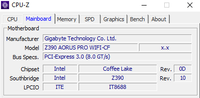
My understanding is that modern boards like mine store BIOS settings in NVRAM, which is stored in the BIOS ROM. But then, how do BIOS settings get reset if you remove the CMOS battery or use the clear CMOS jumper, since this memory is supposed to be non-volatile.
Some values are hard-coded in the BIOS so that default values can be reloaded into NVRAM should they be overwritten/erased.
For example, Secure boot often has hard coded factory keys from the manufacturer that can be reloaded after a BIOS flash or CMOS/NVRAM clear that results in secure boot entering setup mode (therefore disabled).
You can read about Intel UEFI structure at opensecurity.info and although being slightly dated, the pdf’s have some very useful information about NVARs.
In particular look at:
Day 2 - Flash Descriptor (page 5 onwards, Flash Descriptor and Regions)
Day 2 - UEFI (page 39 onwards, UEFI Non-Volatile Variables & Runtime Access)
If you download the Class Materials (John Butterworth - 2014) and take a look at:
Advanced x86 - BIOS and SMM Internals Part 3.pptx (slide 21, Descriptor Mode & slide 30 SPI Regions)
Advanced x86 - BIOS and SMM Internals Part 5.pptx (slide 7, Firmware Storage & slide 8 Firmware Volumes)
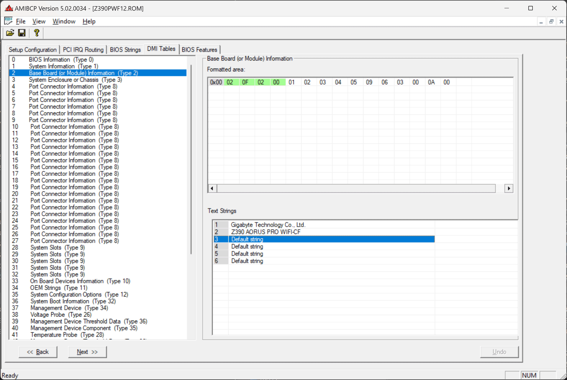
Do you know how to change this, since I remember it being “Default string” on my board?
You can edit this string using AMIBCP:
It is purely cosmetic, I wouldn’t worry about it.
Also, I forgot to ask this in my previous post but why wouldn’t Q-Flash work, since it worked for the modded F9 BIOS? I also want to try flashing this with a programmer, but I assume that will be much more of a hassle since I will have to combine the modded BIOS region with all the other regions on the chip, correct?
At some point Gigabyte updated Q-Flash to no longer accept modified BIOS.
You don’t need to decontruct/reconstruct the BIOS. Just modify the BIOS you want with CoffeeTime and flash with either Intel FPT or Hardware programmer.