Hey!
For starters my motherboard is a Z490 Dark KP.
I flashed a BIOS via FLASHBACK, and this is what happened: the board boots up, then stops for 2 seconds at 63 , then stops at 65 about 4 seconds long, then 4 seconds at 6F , then 7F for 4 seconds as well – then proceeds to boot, but no video output is detected (= d6 ). - here you can check what the POST codes mean
Then according to the LED indicator, I’m in the BIOS (= A6 ) - but obviously no video output. It doesn’t matter from which BIOS chip I boot, the issue is persistent though I only flashed the BIOS on 1 chip – and of course, FLASHBACK doesn’t solve the issue, no matter what BIOS I flash.
The board sometimes instead of entering the BIOS (theoretically → "A6 ") gets past the POST process and tries to enter the OS – this “theory” is supported by the LED indicator which displays the CPU temps after the POST process by default. After about 10 seconds, the CATERR LED lights up. It’s also important to note that the keyboard receives power during the POST process but after the board attempts to enter the OS, it does not.
It isn’t the GPU (it was working before and it is working in another computer). I already left the battery out for a whole night, but nothing. Also rebuilt the computer, and apart the CPU (which I cannot test since I don’t have another compatible motherboard) every component is functional.
I’ve ordered an SPI programmer but to be honest doubt it’ll work since I only flashed the BIOS on 1 chip, yet none of them works - what do you think, will it work?
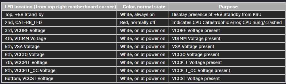
FromxDevs.com Z390 Dark KP analysis: “This is CATERR_LED, to indicate CPU Catastrophic Error condition. If you ever see this red LED to come on, it means CPU failed to run desired settings/clocks, you got cold-bug in extreme overclocking session or CPU/board are simply faulty. There are also two red LEDs between DIMM slot latches and SAFEBOOT button, to indicate memory training failure. DIMM1_FAIL LED is bottom one, showing that CPU having issues to train memory installed in slot DIMM1. DIMM2_FAIL LED does the same thing for far DIMM2 slot. In normal operation these should be off.”
This may be an EVGA “Kind of bios recovery” that wasn’t complete, similar to a loop.
I saw a Gigabyte board do this, after a bios mod and a complete boot cycle, after 2 successful boots into Windows and playing some test/gaming, it was automatedly recovered overwriting the mod on the 3rd boot…
Indeed, the strange part is the BACKUP bios not working as intended here… it gives the ideia that maybe there’s a corruption in bios, a possible EC corruption, some boards have a separate IC for EC, ME FW and TPM or an IC for both, being the main bios in another one.
Modern bios updates, usually only recovers the main bios region, not touching other sections…
Also a possibility, due to specific EVGA board construction, exists another specific IC HW i/o controller with corruption… (checking bySchematic identification if exists around…doubt it)
Im also of the opinion that programming the SPI_MAIN has a higher change of not fixing it…
My pov only and i do not have any knowledge of this motherboard hardware design, wait for other users.
Now… you said you "Flashed a bios…"what are we talking about here… a MOD bios or an official bios update???
Did you already exposed this issue to EVGA tech support?
The mentioned BIOS was a modded BIOS in which I modified the attributes of the NVRAM variables. And it’s important to note that the first POST code (which stops for several seconds - 63) is just after NVRAM initialization (= 61).
Well, I made a post on their forum but nothing helpful. The board was purchased second-hand (without the original packaging) and I cannot find the serial number – therefore I can’t write to the official support
Yeah… It’d be hilarious if I couldn’t use the board anymore (especially in this price range) because I had a bad flash. Like I just don’t understand how the other chips have been effected - or another idea I had that it’s something with the CMOS chip (as I made the modifications in the NVRAM).
I’m aware of this but I highly doubt it that it’s the CPU - it just doesn’t make sense. And again, if the board enters the BIOS automatically, I can leave it on for several hours and there is no CATERR LED, only if it tries to enter the OS
Well seems that something was messed up, that affected bios structure outside the NVRAM volume mods you made… you better grab a programmer, dump both ICS and start checking them against the original bios, other than that its time for paying a professinal Tech Lab.
Good luck, all the best.
You should wait for other users pov.
Yeah, that’s what I was afraid of - there isn’t many around here. I don’t know if I trust them more than myself
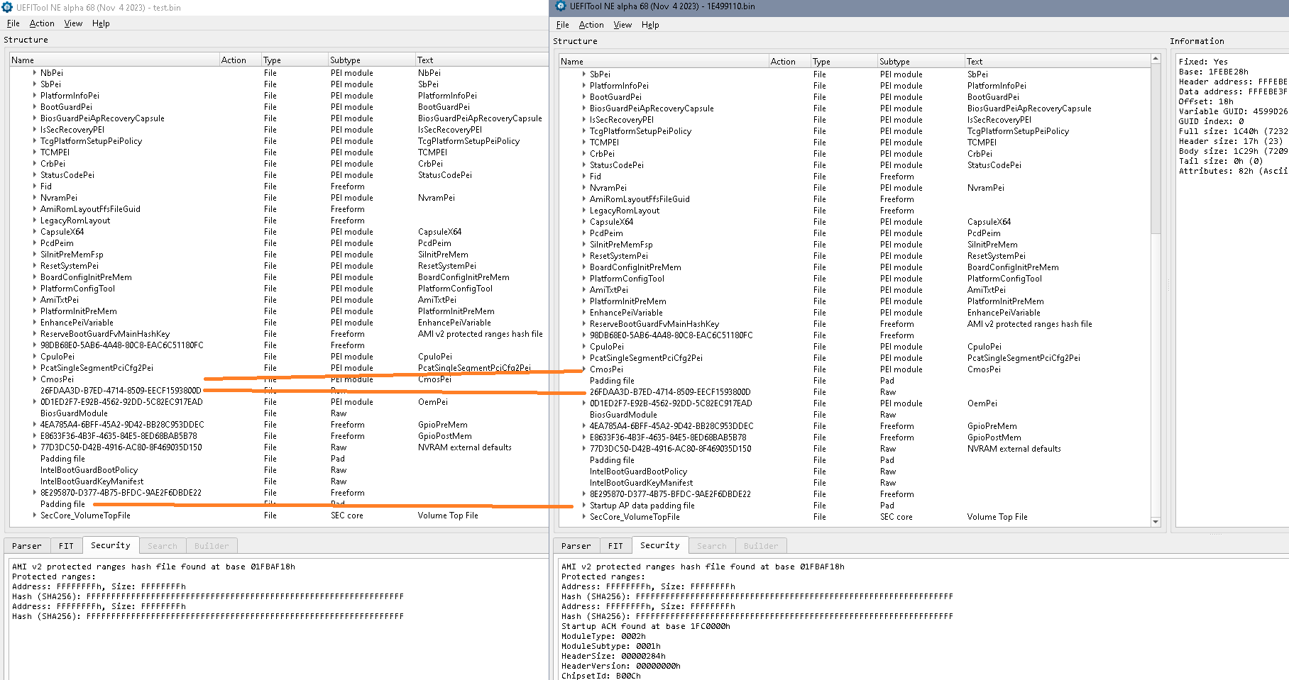
Sure, though I can’t access the drive where the file is located at the moment, but I can replicate it - I know what I changed Here is the link for the modded version - it’s based on v1.10 (only NVRAM attributes were changed, the other differences are from the rebuilding process in UEFITool)
And I tried all official BIOSes (Family: Z490; Part Number: Z490 Dark K|NGP|N; Type: BIOS; OS: WIN10 and untick “show latest driver”) to recover.
But something just occurred to me: there was a time when I was messing around with modding as well, and flashed a “false” BIOS. The board did boot nevertheless but some things didn’t work as I messed it up. Now the important thing is that I couldn’t recover from that, no matter what BIOS I flashed - till I tried to flash it from another USB port – and it worked! But since I don’t have any display output, I can’t try this. Hopefully I’m right, and when I flashed this modded BIOS, the USB was in the “FLASHBACK port” and not in another. If that’s the case, there is still a chance to recover with the SPI programmer. Though it doesn’t explain why none of the 2 other chips work, as it wasn’t the case last time.
Are you sure about your mod? Inserting pad-files where not wished for is sometimes a bad habit of som UEFITool versions, 0.28 and 0.25 don’t always behave the same. I’d not be too sure that this won’t matter in PEI environment?
They simply flash the complete firmware including FD, ME, complete bios region with fpt! There aren’t any protected ranges defined, FD is ‘write where ever you wish’, too.
I think they have to have a separate storage for NVRAM, I can’t trust that the average user would be happy to do all the bios settings again after each and every bios update? Or is this really the way it works with EVGA boards?
Did you check the board for SPI chips? Under these covers, too?
The only way to get any further with this will be to read alle the 3 bios chips and have a look what their content actually is and to search for one or several other SPI(s).
Well, I won’t say I’m 100% sure, but in the past I never got it really wrong – apart from the time I mentioned but that I was kinda expecting (and since I’ve 3 BIOS chips, I wasn’t really worried if one got corrupted – but it seems that it can happen to all 3 at once)
As I said, it was working beforehand – and the process was the same. But I wasn’t actually aware of this so thank you – you might be right!
Well, not exactly - I specifically need the attributes to be modified
That’s indeed funny but I never used FPT (with this board), especially not their scripts, so it isn’t the root of the issue.
Well yeah, if you update the BIOS all your profiles, settings, etc. are gone – I might be wrong, but to my knowledge the CMOS chip might be integrated to the PCH (since I couldn’t find it). So yeah, it is how it works - isn’t it the same by other manufacturers?
Yeah, I found BIOS1, but not BIOS2 and BIOS3. I removed the covers, but they weren’t under them – I’d need to removed the heatsinks as well to investigate further.
Yeah, hopefully the SPI programmer arrives next week - and then we can continue from there
Thanks for confirming EVGA update method. Yes, most vendors spare NVRAM and either don’t update ME region or do a ME update with the built in functionality.
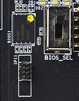
There’s a SPI1 connector close to bios1, maybe? Otherwise it is a little more difficult to attach a clip to this type of chip.
That’s not what I said. There’s a suspect connector close to the chip, but I didn’t find any documentation. So you may find out yourself either by tracing the connections on the pcb, carefully using a multimeter…
EDIT And of course you would have to find out the pin - layout, a ‘standard’ cable might be OK or it might give the wrong connections.
I’ve received the SPI programmer recently, but no success attaching the clip properly.
The only information I found about the SPI header is this. Tried attaching the clip to this header as well, but no success.
Then what type of clip should I try? - Honestly, if this doesn’t work, I’m out of ideas. And it’d be hilarious that due to a bad flash, I cannot use the board anymore.
Read the guides about the use of a CH341 programmer, one can desolder the chip or use other clips like those and those and those. Find out if the header really is connected to the SPI and what the pinout is, create a cable. Try with/without CMOS battery, PSU connected or not or…
I may help / have a look into the content of the chip, but the board and the programmer are on your desk.
I have the same LED being on on my Z790 Dark KP motherboard after flashing a modded BIOS with a newer CPU microcode I’ve added via HEX edit. I can recover the same BIOS chip via flashing a regular BIOS version with the USB flashback button. Flashing my modded BIOS worked both in Windows / FPT and in the BIOS from a flash drive, but every time I flash it the board gets stuck on post code 65 with the Caterr_LED on. There doesn’t seem to be a BIOS lock since FPT worked without any issues, but still can’t figure out what I’m doing wrong. My FIT tables is properly edited and showing every mCode line correctly.
From the 790 KP manual:
Post Code 63-67: CPU DXE initialization is started
I’d propose you open a separate thread since it’s a different problem.
Otherwise you might post / attach the modified firmware so that more people can have a look or you continue to wait for someone who had precisely the same error with this machine and the corresponding solution.
Would something like this work? (I’m from the EU, and don’t want to wait for AliExpress shipping times - so I need something available in EU) + it says in the description that RT809H is supported, but doesn’t mention CH341A, should I be concerned?
If not, just replace the the SOP8 clip with this?
Yeah – I will have 2 weeks off during the holiday period, so I’ll have time investigating the whole issue if I have the right tools
The principle might work, but this isn’t a clamp so you’d need the correct size = pin distance between both pin- rows for (all) your chip type(s). At least bios 1 is WSON which comes afaik in a mm size. Note the chip type, check datasheet, find pin / solder pad distance.