First of all, Hi, i’m new on this forum, and i’m having alot of trouble with my notebook for about a couple of weeks.
The main problem was :
I tried to update the bios of the notebook for compatibility issues in windows 8.1 and windows 10.
The bios update failed, it looked like ieverything was fine, except when i rebooted the computer, it never went on again.
Even the charger light was not going on anymore.
So, after a while, i ordered a new bios chip on the internet, pre programmed, soldered it into the notebook, and there it came alive again ![]()
The only problem is, after 10 seconds the fan will go to full 100% (5200rpm) the processor speed is limited to 930Mhz instead of 1.7Ghz, and after 1.5 hours the laptop suddenly shuts down without any warning.
So it’s pretty unusable at the moment.
After some research, i found out BD PROCHOT was the cause of this problem, and downloaded Throttlestop. Now it runs at full speed again, but still it shuts down after 1.5 hours or so.
Did some more research, and found on a forum someone with exacly the same problem.
He was talking about the Bios regions, and one region was not properly flashed, and that would be the MEI region.
Now my question is, how can i flash the firmware on ie, what files do i need ?
According to the drivers from asus itself, the MEI version is 6.0.0.1179
Already tried to flash a different file (after some research on tthis forum of course) i only get the following message :
Trying to connect to MEI driver…
Error 8193: Intel (R) ME Interface : Cannot locate ME device driver.
I’m using the DOS version to flash it, but it seems not to be working.
So please can someone help me with it ?
Greetings, Chris
Hello,
1. Install the Intel MEI driver from the ME thread, section D1 (6.2.50.1050).
2. Run MEInfoWin -verbose and MEManufWin -verbose tools which can be found at the ME thread, Section C2 (System Tools v6.x 1.5MB/5MB) and show me the results.
3. Run Flash Programming Tool with command FPTw -d spi.bin and check if you get Error 26 or not. If you hopefully don’t, compress and attach the resulting spi.bin file.
As always, ASUS doesn’t include the ME region at their laptop BIOS releases which only houses the EC + BIOS region. However, I found online a full 4MB dump of your model so if we need to reflash the ME region, now we can with settings and everything configured. That requires you to not receive error 26 at step 3 though. Before we do that though:
a) Follow steps 1-3 and provide the results of the last two.
b) Run Flash Programming Tool with command FPTw -greset and check if after the reset your 1.5 hour problem is gone.
Ok, thanks for the very quick reply ![]()
I’ve done everything you asked, and the fun thing is… i didn’t get a error 26 ![]()
It looks like it is even worse, but i don’t know that for sure yet.
even FPTw -greset wouldn’t work
I’ve putted the files as attachements.
Greetz, Chris
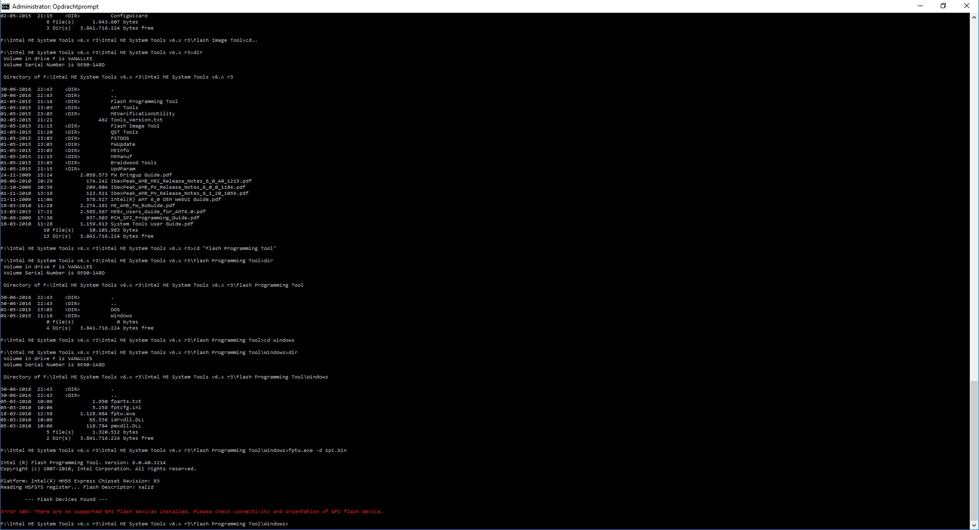
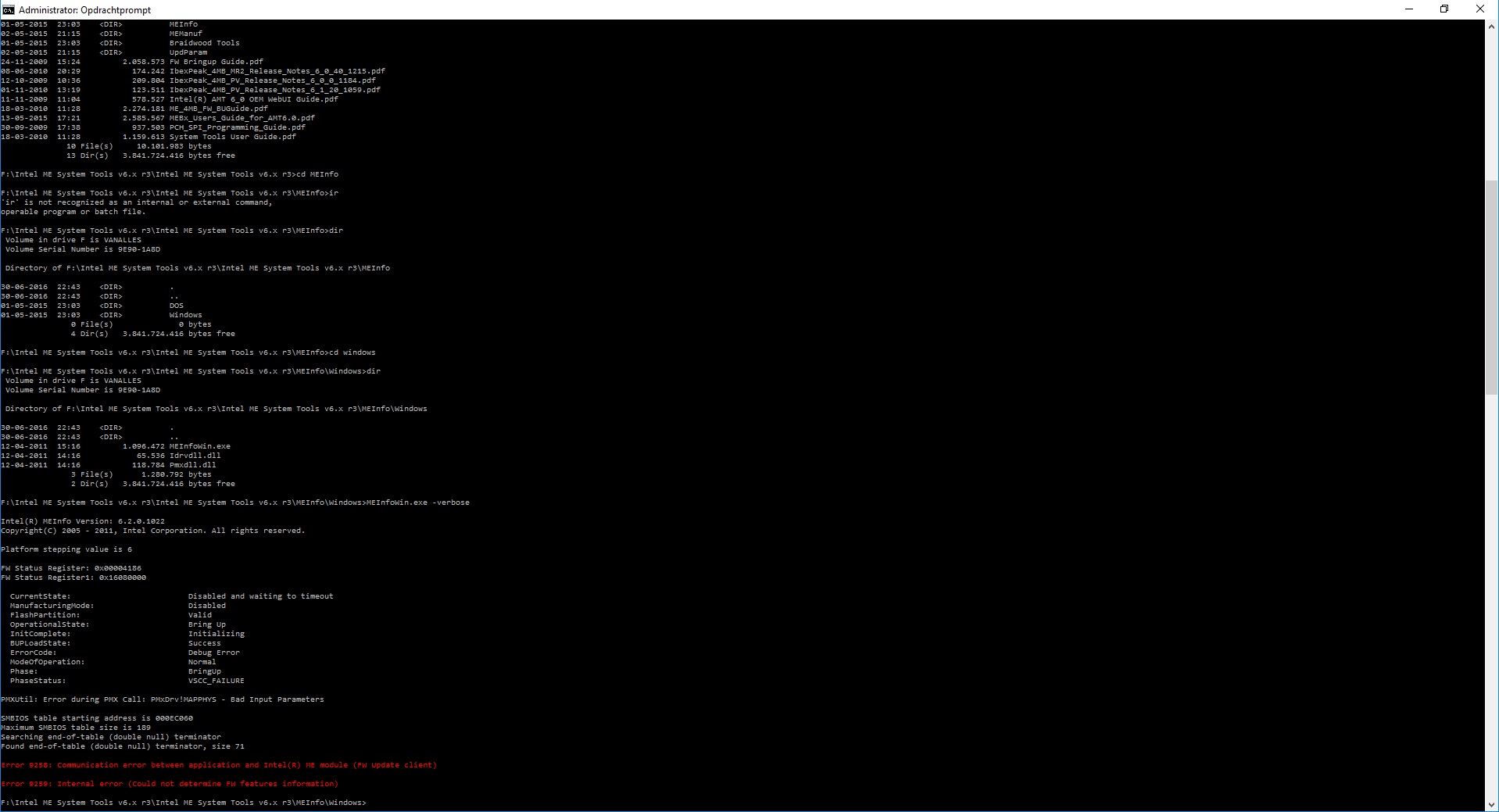
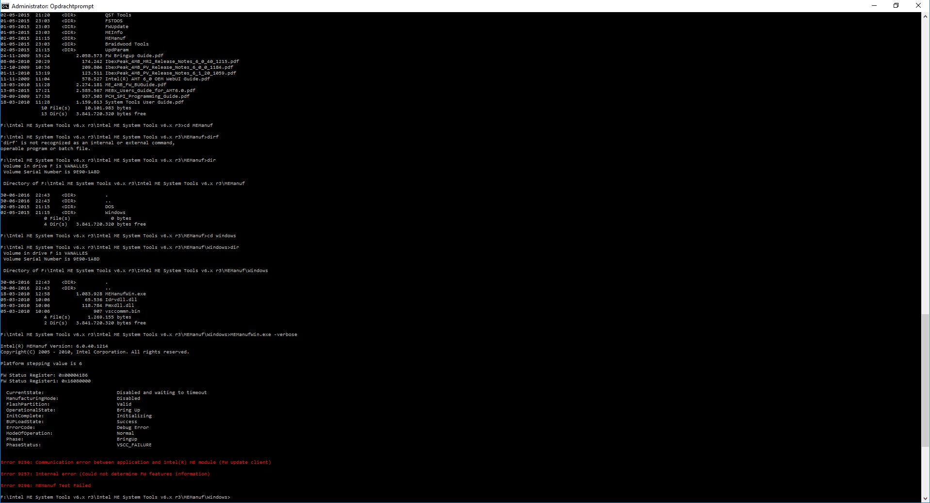
I think I know what’s wrong even though this is the first time I’ve seen this problem. The new chip is probably not the same as the older one. Besides the BIOS, data can be written to the SPI chip by the ME as well. In order for the ME to work properly with the BIOS/SPI chip of the system, the OEM needs to add the chip specifications at the Vendor Specific Configuration (VSCC) table which can be found at the Flash Descriptor (FD) and is edited via Flash Image Tool. At the MEInfo picture I can see that the ME is halted due to a VSCC_FAILURE error. I assume that it cannot find the soldered chip info at the VSCC table of the FD and thus it can neither write to the SPI/BIOS chip nor work in general.
Now, just like the ME Region, FD is locked and cannot be read or written under normal circumstances for security reasons. If it’s unlocked though, you can rewrite it with an added VSCC entry and also reflash the ME region fully (not possible with FWUpdate) to eliminate any issues there as well. That’s why I asked for the fptw -d command result. If you get error 26 then your FD is locked, otherwise unlocked.
In your case though, FPT doesn’t include the chip information for that new chip as well so that’s why it cannot detect a chip as the error says. For FPT, you easily add any chip info at the fparts.txt accompanying file. You will need to know the exact chip model and it’s specifications (usually found online). Do you know what chip your system currently has? Another alternative to “bypass” the lack of your spi chip at the FPT database is to use another flasher such as flashrom but you will need to use Linux for that.
Generally the fact that the pre-flashed chip is not the same as the original and the fact that whoever flashed it didn’t check if it worked long enough has caused you many issues now. Basically the ME cannot initialize and thus terminates the system after a set amount of time. In my experience it’s usually 30 minutes but in your case (maybe the older hardware) it’s longer than that. Still, it’s not something that can be ignored unfortunately.
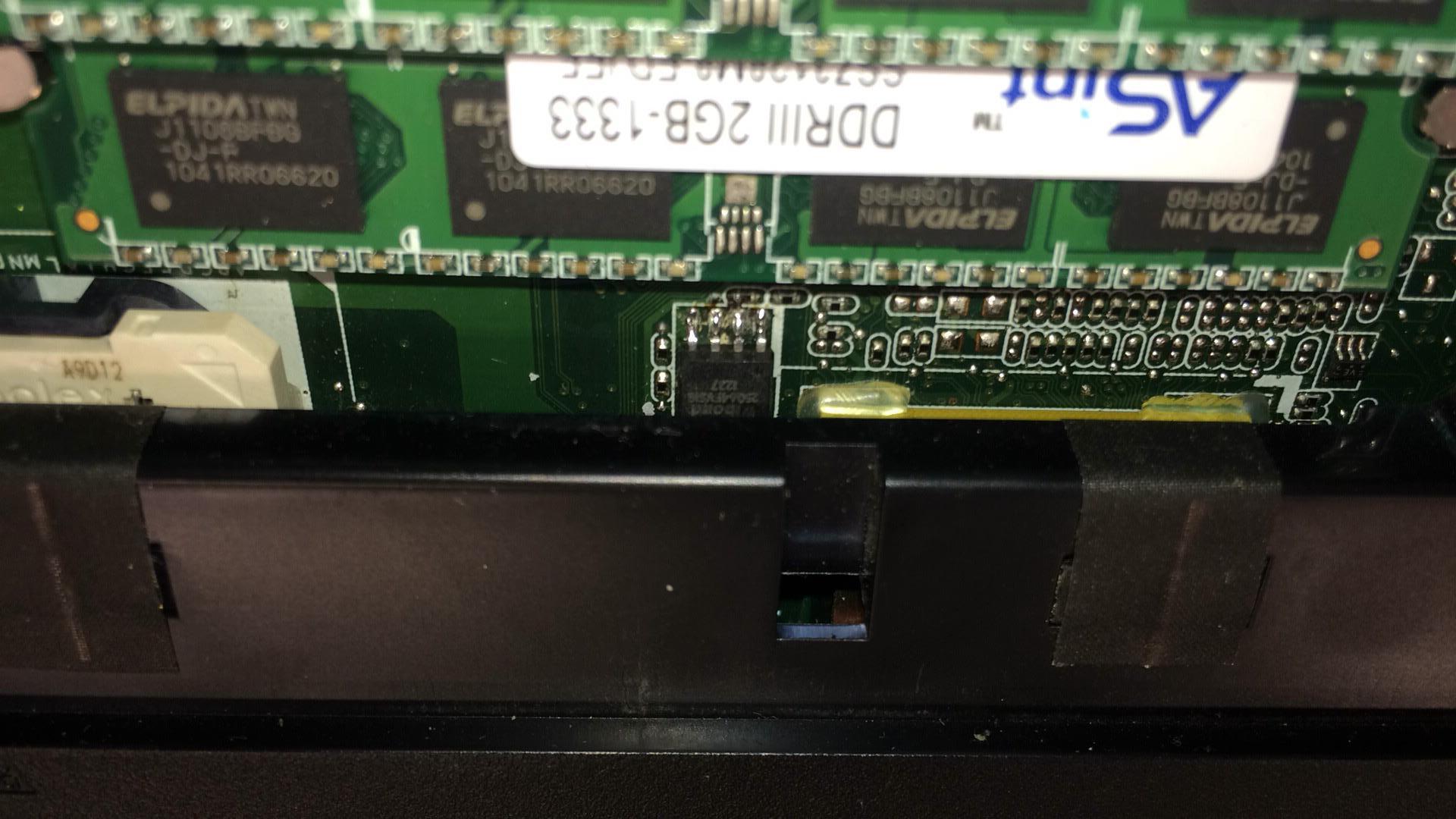
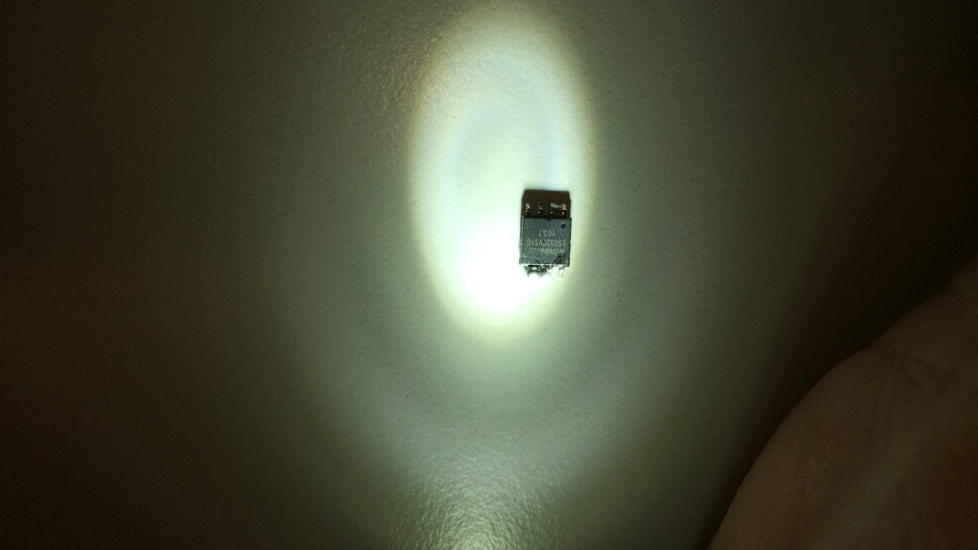
Ok, thanks for the reply again. I figured out what chip is in the notebook at the moment, and what chip was in it before.
The original was the Winbond 2503BVSIG 1037
The New one is the Winbond 25Q64FVSIG 1227 or 1237 (couldn’t read it very good)
Edit : the chip i ordered came from bios-chip24.com
Here are the pictures.
Greetings, Chris
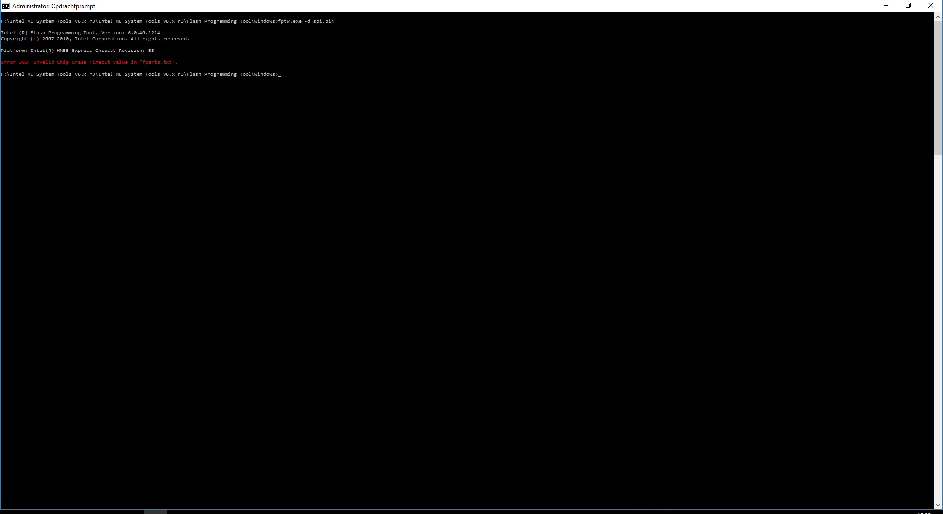
Try the following fparts.txt file which is from the latest fpt v11 and includes your chip.
fparts.rar (1.66 KB)
Ok, i replaced the txt file in the flash tool.
Now i get another error code.
Greetings, Chris
OK, finaly i managed to get some information out of the chip.
Unfortunately it’s not verry good news…
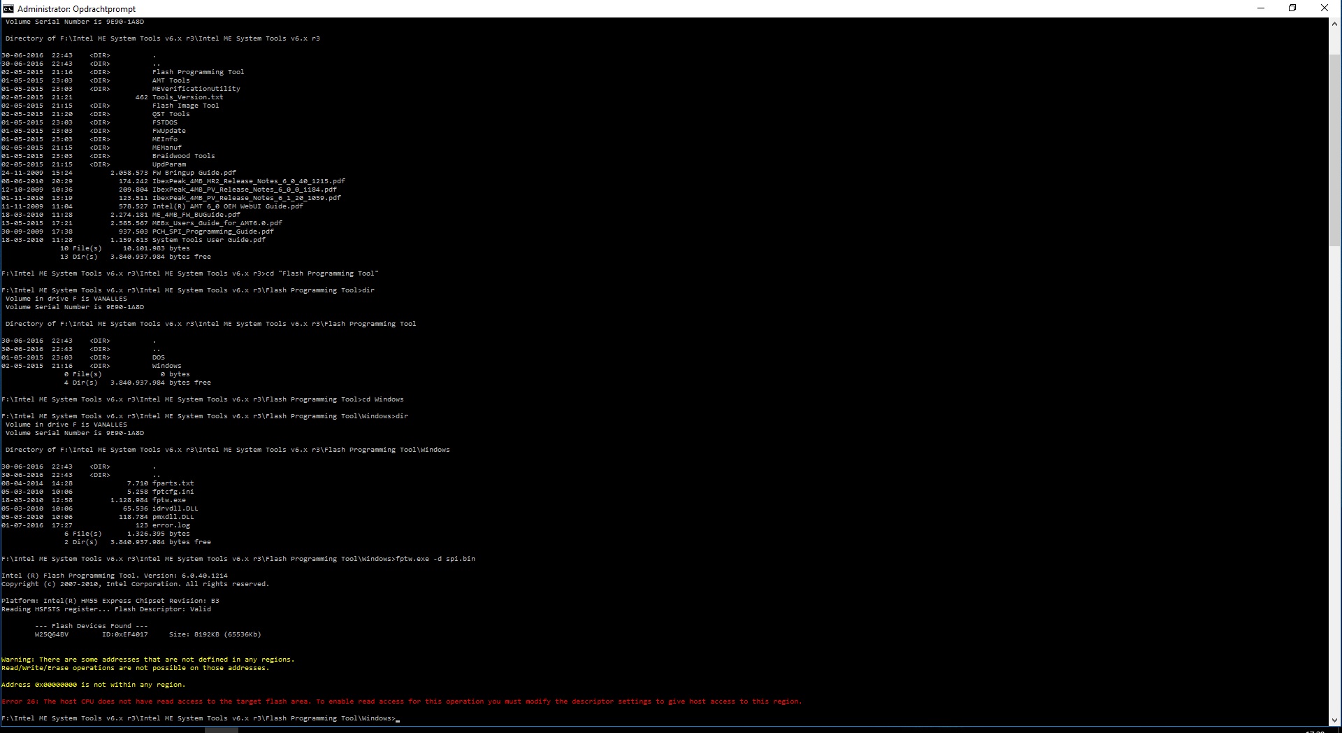
First observation is that whoever pre-flashed the chip did not do a very good job. The first address (0x00) should be included at the FD region as always. Check with command fptw -i to view the regions. Second observation is that your FD is locked. So you can either try the pinmod (very difficult) or reflash the chip with a programmer. That’s the only way. Depending on what you plan to do, the instructions afterwards change a little bit.
Yeah, i noticed that something was wrong with the bios before, but didn’t know exacly what it was.
So i sent an email to the company who sold the chip, and told them something was wrong with the chip.
Also i’m going to mail them again, and post a link to this thread in it, so he can read it back.
Now i don’t know exacly what i’m going to do. I was not planning to buy myself a chip programmer, and i even don’t know how they work.
Also there can be a little problem, because the flat cables on the mainbord (the one of the touchpad, and the one to the powerbutton panel) are worn out, and starting to get damaged.
So i hope everything will survive as i need to open the notebook again. I don’t know what pins in need to do something with when i’m planning to do the pinmod.
Greetings Chris (PS, here’s the screenshot of FPTw.exe -i.)
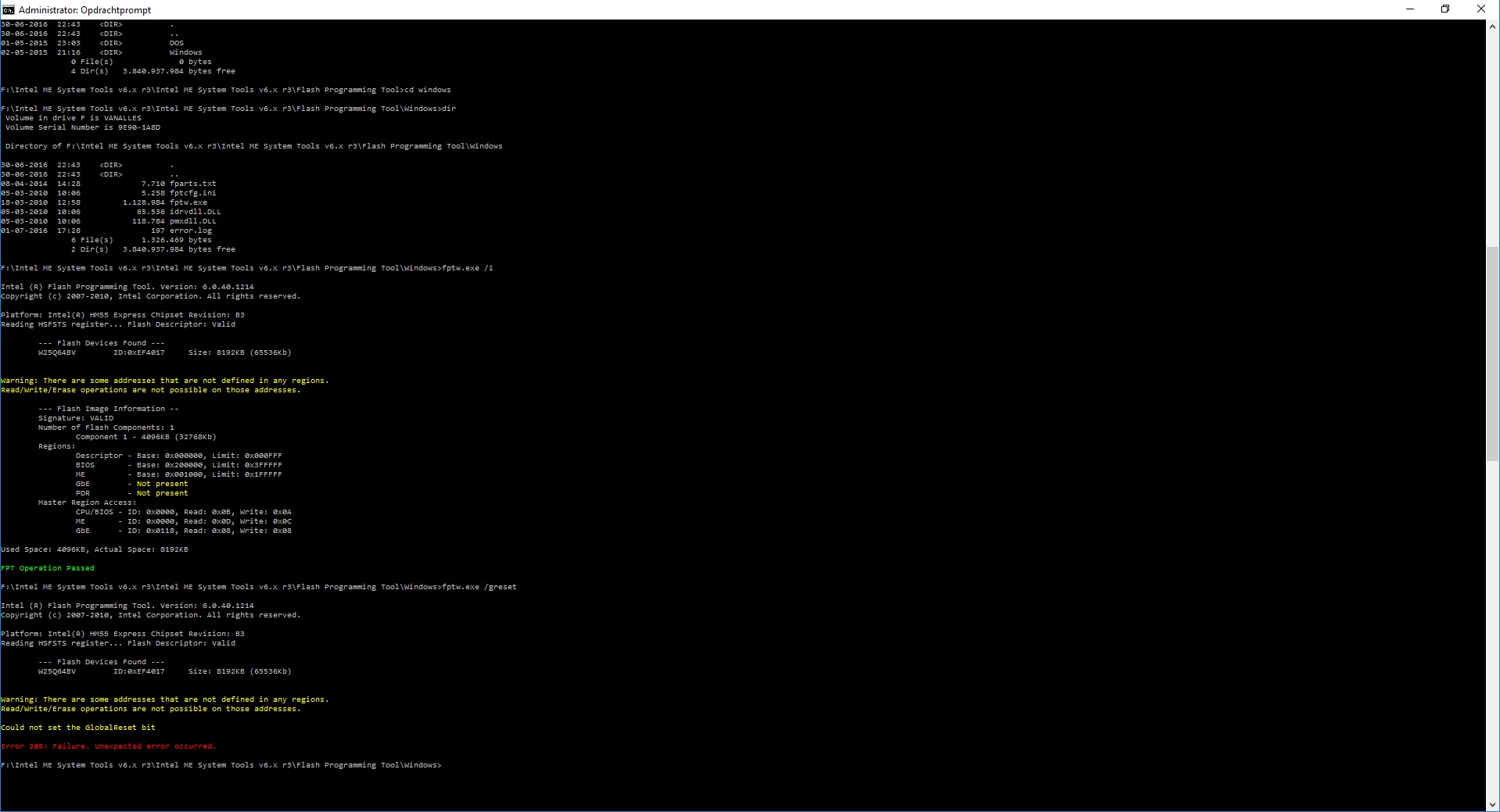
After seeing that FPT reports 8MB, I checked the datasheet from winbond and the chip is indeed 8MB. Another problem there. The system originally had a 4MB chip so obviously the Flash Descriptor was set at Flash Image Tool as having 1 SPI component of 4MB, not 8MB. That’s why it says that some addresses are not defined, meaning the unused 4MB. Even if there’s empty space at the chip/image, FITC assigns the rest of the padding to the ME region by default, something which is not done here obviously. If the FD is unlocked I guess we can fix that as well but at this point, they have messed up royally. Yes a bigger chip will work in place of the older smaller one but that doesn’t mean that the software/firmware will as well without needed modifications. If they wanted to do that they should have a) changed the component density at the FD, b) the VSCC table at the Flash Descriptor and c) using a cleaned-up ME region otherwise junk from other systems may cause issues. I can’t blame them for c but especially a & b are very important.


For the pinmod to work you need to detect the audio chip, check it’s datasheet > pinout diagram and find two pins (DVDD and SDATA-OUT) which need to be sorted with something metallic/conductive (tweezers etc) while the system posts and released shortly afterwards. Usually those two pins are numbers 1 & 5 but it depends so that’s why I said to check the audio chip datasheet. The problem with that solution to bypass the FD lock is that the pins can be extremely small nowadays which makes this process very hard even on desktop systems where there is more space to work with.
OK, that’s clear. now i only don’t know if it’s possible to rewrite this chip after the FD is unlocked ?
I will try to look for the audio chip and try to short it.
Will it stay unlocked after that, even when i restart the computer ?
Or do i have to unlock it again when the computer restarted ?
Greetings, Chris
It’s temporary and will reset back to default after a reboot. However, once the FD is unlocked, you can reflash the FD and apart from fixing all the other issues, you can also disable the lock. Afterwards you won’t need pinmod and can work directly via FPT while being careful of course. If you manage to make pinmod work then let me know and I’ll tell you what to do. Otherwise, you should ask them to send another chip which is identical to the old one (will solve almost all your problems) or at least with properly configured firmware inside to work with the new one for some hours (verified, ME is ok) and not just at the BIOS.
I think it’s nearly impossible to reach the audio chip on this motherboard. I cant connect the 2 pins together, while the lapto is still connected to everything. The Chip is on the bottem side of the mainboard, and there’s no lit to open so i can reach it easilly.
I think i have to find someone who can reflash the original chip for me, because i still have the original one.
Edit: I also uploaded a picture of the motherboard.
I presume there where the blue rectangle is, is the audio chip.
Greetings, Chris
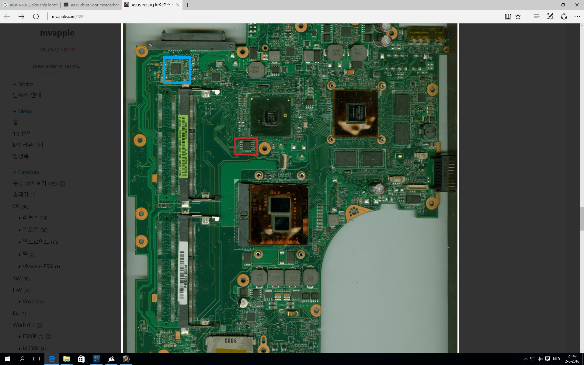
I can see the Realtek logo so yes, it’s there. For realtek it’s usually pins 1 & 5 but as I said, and as you figured out, the procedure is very difficult to do nowadays. If the original chip works you can definitely reflash it and solder it. No matter what you do though, desoldering and soldering back is required with the locked FD. Depending on what you depending on what you want to do, and since I have another dump of your model, I can create a SPI image for you, either 8MB or 4MB although the latter is preferred to avoid adding VSCC entries or similar. It’s doable but takes more time and I haven’t tested it before although it has no obvious reason to fail after flashing. No matter what you choose, the ME needs to be cleaned & configured and you should keep the FD unlocked in case you discover something later and want to fix it without any soldering or similar. I can help with these. So when you decide what to do, let me know.
Then i still have to buy me a programmer. I’m going for the safe option, desolder the chip ( I will make a modification to the case, so i dont have to open the complete notebook again) reflash one of the chips I have, and then solder it back.
I think there should be no reason why the old chip wouldn’t work anymore, it only failed flashing, so I guess it can be erased, and reflashed. I don’t know where you live, and if you have a programmer, or another member of the forum ?
As I said before, i dont know what programmer I need to have, and I definitely don’t want to spent a lot of money on a machine that i probably use once, and I don’t know how to use it.
Greetings, Chris
Yes the old chip should be fine, just badly flashed. You can use a cheap programmer to do the job you want on such a chip.
Ok, first of all thanks for all the help.
I’m going to order a EEPROM programmer, and then i will try to rewrite the complete bios chip.
But I ws thinking, the original bios chip only the bios itself failed to flash, so i guess the ME firmware still is in it then ?
When i got the EEPROM programmer, i will get back on here for some help ![]()
Greetings, Chris
This is the one i’m going to order, including the SOIC 8 test clip.
