[Guide] Enhanced BIOS Modding of Award BIOSes

Download Link: https://dl.dropboxusercontent.com/u/7372…d5p_f8n_mod.zip

The brief How-tos are for AWARD BIOSes and mainly specific to this mod,
but i hope others will also find it useful in other scenarios.

Note that this mod is intact in most if not all aspects possible and thus
things I wasn’t sure about are not forced to get managed and are not included at all.
The mod is behaving as it should (I’m running this on my live system) and this way you can (should) flash it
with the BIOS built-in QFlash, but of course first make sure your current one is backed up (see later).


Module Modifications

RAID750.BIN 3.0.1540.59 → 3.2.1540.15
UI750.BIN 3.0.1540.59 → 3.2.1540.15
ahci.BIN 3.0.B.0(3.0.A) → 3.1.2.0
JMB59.BIN 1.06.59 → 1.07.28
RTEGPXE.BIN 2.37(only PXE) → 2.54(PXE+RPL)

Original Layout

1
2
3
4
5
6
7
8
9
10
11
12
13
14
15
16
17
18
19
20
21
22
23
24
25
26
27
28
29
30
31
32
33
34
35
36
37
38
39
40
41
42
43
44
45
 
CBROM32_198.EXE V1.98 [08/27/08] (C)Phoenix Technologies 2001-2008
 
******** M79XTUD5.F8n_Orig BIOS component ********
 
No. Item-Name Original-Size Compressed-Size Original-File-Name
================================================================================
0. System BIOS 20000h(128.00K)12CC4h(75.19K)m79xtud5.BIN
1. XGROUP CODE 0F1C0h(60.44K)0A2BDh(40.68K)awardext.rom
2. ACPI table 06E1Eh(27.53K)0324Fh(12.58K)ACPITBL.BIN
3. GROUP ROM[18] 04970h(18.36K)03098h(12.15K)ggroup.bin
4. GROUP ROM[20] 05BD0h(22.95K)035F6h(13.49K)ffgroup.bin
5. SETUP0 018A0h(6.16K)00A75h(2.61K)_ITEM.BIN
6. TSEG0 00490h(1.14K)00398h(0.90K)y2group.bin
7. YGROUP ROM 0B680h(45.63K)058F7h(22.24K)awardeyt.rom
8. GROUP ROM[22] 0F630h(61.55K)0083Eh(2.06K)tgroup.bin
9. GROUP ROM[23] 0F630h(61.55K)0015Bh(0.34K)t1group.bin
10. GROUP ROM[24] 0F630h(61.55K)0015Ch(0.34K)t2group.bin
11. GROUP ROM[ 0] 08470h(33.11K)0313Eh(12.31K)_EN_CODE.BIN
12. PCI ROM[A] 0F400h(61.00K)097D9h(37.96K)RAID750.BIN
13. PCI ROM[B] 05200h(20.50K)03382h(12.88K)ahci.BIN
14. OEM3 CODE 0C000h(48.00K)0704Ch(28.07K)ahci.DLL
15. PCI ROM[C] 07A00h(30.50K)04479h(17.12K)JMB59.BIN
16. PCI ROM[D] 0C800h(50.00K)0711Eh(28.28K)RTEGPXE.LOM
17. OEM0 CODE 034F6h(13.24K)0265Bh(9.59K)SBF.BIN
18. GV3 05223h(20.53K)022FBh(8.75K)AGESACPU.ROM
19. MINIT 0DE53h(55.58K)0DE7Bh(55.62K)MEMINIT.BIN
20. HTINIT 05381h(20.88K)053AEh(20.92K)HT.DLL
21. 2 PE32 in MB 006BDh(1.68K)006ECh(1.73K)HT32GATE.BIN
22. OEM1 CODE 0A400h(41.00K)0A428h(41.04K)09561117.BIN
23. LOGO BitMap 4B30Ch(300.76K)0E56Fh(57.36K)FXT_UD5P.BMP
(SP) NCPUCODE 03800h(14.00K)03800h(14.00K)NCPUCODE.BIN
(SP) HOLE0 4D38h(19.30K) 4D38h(19.30K)CIMRD790.B2
(SP) HOLE1 2FE8h(11.98K) 2FE8h(11.98K)CIMSB700.B2
(SP) HOLE2 DC00h(55.00K) DC00h(55.00K)UI750.BIN
(SP) HOLE3 E8Dh(3.64K) E8Dh(3.64K)ECCODE7.BIN
 
Total hole area space = 30000h(192.00K)
Total compress code space = A4000h(656.00K)
Total compressed code size = 840F5h(528.24K)
Remain compress code space = 1FF2Bh(127.79K)
 
** Micro Code Information **
Update ID CPUID | Update ID CPUID | Update ID CPUID | Update ID CPUID
------------------+--------------------+--------------------+-------------------
1000085 00001040|
 

Mod Layout

1
2
3
4
5
6
7
8
9
10
11
12
13
14
15
16
17
18
19
20
21
22
23
24
25
26
27
28
29
30
31
32
33
34
35
36
37
38
39
40
41
42
43
44
45
46
 
CBROM32_198.EXE V1.98 [08/27/08] (C)Phoenix Technologies 2001-2008
 
******** M79XTUD5.F8n_RAID3.2.1540.15_AHCI3.1.2.0_JMB36X1.07.28_RTPXERPL2.54_NCPUCODE_ITEM.BIN BIOS component ********
 
No. Item-Name Original-Size Compressed-Size Original-File-Name
================================================================================
0. System BIOS 20000h(128.00K)12CC4h(75.19K)m79xtud5.BIN
1. XGROUP CODE 0F1C0h(60.44K)0A2BDh(40.68K)awardext.rom
2. ACPI table 06E1Eh(27.53K)0324Fh(12.58K)ACPITBL.BIN
3. GROUP ROM[18] 04970h(18.36K)03098h(12.15K)ggroup.bin
4. GROUP ROM[20] 05BD0h(22.95K)035F6h(13.49K)ffgroup.bin
5. SETUP0 018A0h(6.16K)00A75h(2.61K)_ITEM.BIN
6. TSEG0 00490h(1.14K)00398h(0.90K)y2group.bin
7. YGROUP ROM 0B680h(45.63K)058F7h(22.24K)awardeyt.rom
8. GROUP ROM[22] 0F630h(61.55K)0083Eh(2.06K)tgroup.bin
9. GROUP ROM[23] 0F630h(61.55K)0015Bh(0.34K)t1group.bin
10. GROUP ROM[24] 0F630h(61.55K)0015Ch(0.34K)t2group.bin
11. GROUP ROM[ 0] 08470h(33.11K)0313Eh(12.31K)_EN_CODE.BIN
12. PCI ROM[A] 0E800h(58.00K)0C4B2h(49.17K)RAID750.BIN
13. PCI ROM[B] 06600h(25.50K)03A38h(14.55K)ahci.BIN
14. OEM3 CODE 0C000h(48.00K)0704Ch(28.07K)ahci.DLL
15. PCI ROM[C] 08000h(32.00K)046B3h(17.67K)JMB36X.BIN
16. PCI ROM[E] 07A00h(30.50K)03B55h(14.83K)DUMMY.DUM
17. OEM0 CODE 034F6h(13.24K)0265Bh(9.59K)SBF.BIN
18. GV3 05223h(20.53K)022FBh(8.75K)AGESACPU.ROM
19. MINIT 0DE53h(55.58K)0DE7Bh(55.62K)MEMINIT.BIN
20. HTINIT 05381h(20.88K)053AEh(20.92K)HT.DLL
21. 2 PE32 in MB 006BDh(1.68K)006ECh(1.73K)HT32GATE.BIN
22. OEM1 CODE 0A400h(41.00K)0A428h(41.04K)09561117.BIN
23. LOGO BitMap 4B30Ch(300.76K)0E56Fh(57.36K)FXT_UD5P.BMP
24. PCI ROM[D] 10000h(64.00K)095A6h(37.41K)RTEGPXE.LOM
(SP) NCPUCODE 03800h(14.00K)03800h(14.00K)NCPUCODE.BIN
(SP) HOLE0 4D38h(19.30K) 4D38h(19.30K)CIMRD790.B2
(SP) HOLE1 2FE8h(11.98K) 2FE8h(11.98K)CIMSB700.B2
(SP) HOLE2 E000h(56.00K) E000h(56.00K)UI750.BIN
(SP) HOLE3 E8Dh(3.64K) E8Dh(3.64K)ECCODE7.BIN
 
Total hole area space = 30000h(192.00K)
Total compress code space = A4000h(656.00K)
Total compressed code size = 8D69Bh(565.65K)
Remain compress code space = 16985h(90.38K)
 
** Micro Code Information **
Update ID CPUID | Update ID CPUID | Update ID CPUID | Update ID CPUID
------------------+--------------------+--------------------+-------------------
1000085 00001040|


Notes about Modules:
AGESA module is unchanged (3.7.1.0), as the Motherboard already supports all possible AM3 CPUs.
For Microcode updates see NCPUCODE changes below.
Modified the Decompressor to correctly manage Hole area for UI750.BIN.
DUMMY.DUM module is a fake PCI OROM what will never be invoked (VEN_5678:DEV_1234)
and is merely a pad for the remaining gap between newly updated and Sensitive modules.
The Realtek Boot ROM has RPL support too, but this ROM is designed so that RPL mode is separated
as an additional PCI OROM, so if you really want it, you have to redirect the initialization of the
OROM itself, or just go with the cut-off RPL parts without PXE.
Or even better, you can hook the switching to appear as an additional Setup submenu,
but RPL is probably unlikely to be needed at all, so this would be mostly a waste of time.
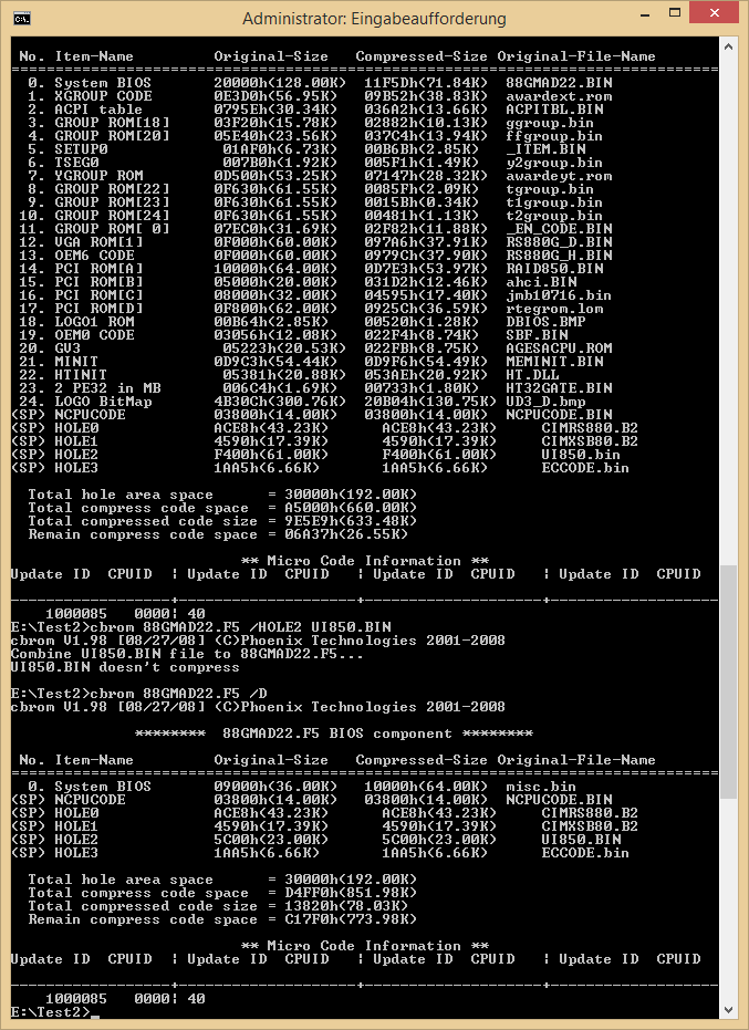

_ITEM.BIN Changes

SATA ESP option (for AHCI mode) is Enabled
BIOS Logo defaults always to Disabled
Onchip Ide Channel option is "Show only"
Onchip Ide Channel1 option is "Show only"
PATA Channel Mapping option is "Show only"

Notes about _ITEM.BIN:
These changes are only minor things. ESP (eSATA) is not tested to work and it makes not much sense at all, but hey.
Annoying BIOS Logo will be disabled when selected the "Load BIOS/Optimized Defaults" by default,
but of course it can be enabled/disabled any time later.
I was setting the IDE Channel options non-selectable (show only), because these settings could interfere
with certain AHCI/RAID/IDE setups (see >this AMD SB700/710/750 Register Reference Guide<), so I decided to leave them only as informational fields.


NCPUCODE.BIN Changes

Full List of CPU Microcode Patches:
Date:2008/05/01 CPUID:100F40 PatchID:01000085 -> Unchanged
Date:2010/02/17 CPUID:100FA0 PatchID:010000BF -> Date:2011/10/24 CPUID:100FA0 PatchID:010000DC
Date:2010/03/11 CPUID:100F41 PatchID:010000C6 -> Unchanged
Date:2010/03/11 CPUID:100F62 PatchID:010000C7 -> Unchanged
Date:2010/03/31 CPUID:100F43 PatchID:010000C8 -> Unchanged
Date:2010/03/31 CPUID:100F22 PatchID:010000C9 -> Unchanged
Date:2010/03/31 CPUID:100F20 PatchID:010000CA -> Unchanged

Notes about Microcode Patches:
The Microcode updates except for CPUID 100FA0 are currently all up to date (and probably will stay like this),
despite the fact that utils found around are not able to show some or most of these Patches.
"Newer" AM3 CPUs having CPUID 100FA0 (mostly Phenom II X6 CPUs) will be patched to the 010000DC Microcode,
what is anyway left outdated by Gigabyte at PatchID 010000BF in the original BIOS.
This Microcode update will fix Errata #438, #440 and #573 as per AMD documentation
"Revision Guide for AMD Family 10h Processors, order #41322" and is coming from Linux repositories.
Under Linux this will have no effect, because Linux will (should) patch the CPU to the newest (this) Microcodes,
however at the time of writing Windows 7 is only patching a few CPUs at boot time to some "critical" Microcodes:
2008/05/01 100F20(100F2A) - 01000084
2008/04/30 100F22(100F23) - 01000083
2008/03/06 200F31 - 02000032
This means that 100FA0 CPUs will be "left" at the patch level provided entirely by the BIOS
and thus with the old/original patch 010000BF they would be left vulnerable to the above mentioned 3 issues.
By the newest patch 010000DC here we say goodbye to these vulnerabilities.


Useful Key/Button Shortcuts

-In BIOS main screen CTRL+F1 brings up hidden menu(s). This is an AWARD specific combination.
In this case the hidden menu will show up only one item; the Spread Spectrum option for the SB.
This option can produce bugs in certain scenarios and i'm not sure if this BIOS has the workarounds for fixing it,
probably this is why it is hidden. Details about this can be found in AMD SB700/710/750 BIOS Developer's Guide.

-At boot time Alt+F12 brings up the screen to update the Backup BIOS to the image currently resides in Main BIOS.

-Reverting the Main BIOS to the Backup BIOS; switch off Computer, turn off Power supply/pull Power cable until
Mainboard LEDs are out, press+hold Power button, switch on Power/put back cable until switches off again
(after standard 4secs), Power off/cable out again, wait for LEDs, then Power back.
Push Power button and it should bring up a screen (after the main boot screen) telling,
it will revert the Main BIOS to the image currently in the Backup BIOS.

You can see some end-result photos dumped here: https://www.dropbox.com/sh/w6jte68kqdp3r...U7MzYC2/Results

The misc.bin files (UI750.BIN here is misc.bin as per PROMISE specifications) can come in 2 types; one is a bigger one, the other is smaller.
The differences are the bigger one is uncompressed, the smaller one is compressed with the same lzh algorythm. The uncompressed variant is for use
in AWARD BIOSes, the compressed ones are for AMI (regardless of UEFI/non-UEFI).
AMI can use compressed images, but AWARD BIOS is not meant use compressed images in a Hole area. Trying to add a compressed binary will result in an Invalid
BIOS image for QFlash and a chopped layout for CBROM. This happens because the compressed binary contains the same -lh5- compression signature as
the other modules in the BIOS image and thus the Decompressor will treat it as “part of the Decompression Block”. This is very incorrect because we are in
Uncompressed Hole Area and the Decompression block is totally elsewhere in the BIOS image. Also note that Hole areas are not one continuous space,
but they are spread around instead. CBROM will also “feel” the same but it will fail to find any other modules from this point on,
so it will not show up any other content.

Knowing this first we need to release the old UI750.BIN from Hole2

1
 
CBROM32_198 <bios_name> /hole2 release
 

this will invalidate (but not clear out) the Hole2 area.
It is best to clear Hole2 area with 00-s right now: 10000-1FFFF -> 00 in Hex editor.

Now we need to set correctly up the Decompressor to be able to handle the new and bigger UI750.BIN, because if right now we just insert the new binary,
CBROM will tell that "Hole Structure information of BIOS file doesn't match". This is because the Decompressor is using a Hole structure table and if our binary
is bigger than the boundaries set in this table, the binary will not be accepted. Forcing it adding by hand will result in a corrupt BIOS image, since the overlaying
parts after this boundary will be ignored, what is bad for a binary image.
Opening the complete BIOS image directly in a Hex editor is the way go, because the Decompression block is uncompressed (needs to be executed as is)
so we can edit it in place.

@Address 0EF530 we will see this table:
EDIT by Fernando: Image is not available anymore

After the *HOLE* signature there are 4 Hole setups (0..3) numbered 90...93 where 92 is our Hole2 area.
Simplest to interpret these bytes is to treat the 00 10 00 the beginning address of Hole2 (100000) and after these
the 10 is the number of pages that Hole2 needs. For the old UI750.BIN this was set to 0E (=56kB) what should be
enough for the new binary, but we have to increase it as it turned out before. Setting it to 10 (=64kB) will be
more than sufficient.

Now we can insert the new UI750.BIN
1
 
CBROM32_198 <bios_name> /hole2 UI750.BIN
 

Steps like releasing/inserting something with CBROM will also fix all standard Checksums for the whole BIOS image,
so later we can just e.g. release this same binary and readd it, thus refreshing the Checksums all around.

It is always a good idea to check if everything is fine by opening the BIOS image with Awardtool and verify it's integrity
and even extract the components from it. Note that there are some additional 00-s/FF-s around right after various compressed
modules and these will make tools like Awardtool telling that some modules may have incorrect checksum.
I have a feeling that Gigabyte is playing here.

There is one important thing we have to keep in mind: Any module above/before the sensitive modules shall not be released/inserted by CBROM,
because CBROM will readd the sensitive modules and this will end up in a corrupt BIOS image. Sensitive modules in this case are MEMINIT.BIN, HT.DLL and HT32GATE.BIN.
There are some other (risky) methods how to avoid this, but i prefer to simply copy the new/updated modules and paste them after each other to the BIOS image directly
in a Hex editor. The remaining space can then be easily filled out by a Dummy module to fill up the space entirely.

In more detail, this is our old layout:

1
2
3
4
5
6
7
8
9
 

No. Item-Name Original-Size Compressed-Size Original-File-Name
================================================================================
12. PCI ROM[A] 0F400h(61.00K)097D9h(37.96K)RAID750.BIN
13. PCI ROM[B] 05200h(20.50K)03382h(12.88K)ahci.BIN
14. OEM3 CODE 0C000h(48.00K)0704Ch(28.07K)ahci.DLL
15. PCI ROM[C] 07A00h(30.50K)04479h(17.12K)JMB59.BIN
16. PCI ROM[D] 0C800h(50.00K)0711Eh(28.28K)RTEGPXE.LOM


And this is how it looks after the exchange:
1
2
3
4
5
6
7
8
9
 

No. Item-Name Original-Size Compressed-Size Original-File-Name
================================================================================
12. PCI ROM[A] 0E800h(58.00K)0C4B2h(49.17K)RAID750.BIN
13. PCI ROM[B] 06600h(25.50K)03A38h(14.55K)ahci.BIN
14. OEM3 CODE 0C000h(48.00K)0704Ch(28.07K)ahci.DLL
15. PCI ROM[C] 08000h(32.00K)046B3h(17.67K)JMB36X.BIN
16. PCI ROM[E] 07A00h(30.50K)03B55h(14.83K)DUMMY.DUM


We have 4 PCI OROMs and 1 OEM Code, the total compressed space these 5 modules are occupying is 97D9+3382+704C+4479+711E = 1F13E Bytes.
In the new/updated layout padded with Dummy we have to have the same; C4B2+3A38+704C+46B3+3B55 = 1F13E Bytes.
Note that the Realtek OROM was added after the sensitive modules just to the end of the modules (simply inserted by CBROM) as PCI ROM[D],
as the actual order or the OROMs doesn't matter, i.e. they are decompressed to their corresponding addresses identified by 'x' in PCI ROM['x']
wherever they are found in the BIOS image.

Pasting an OROM directly into the BIOS image needs the ROM to be compressed first (can be checked if it has the -lh5- signature in the header).
For extraction i simply used 7Zip, but for compression i used to create a copy of the BIOS file itself and insert it by CBROM.
After this open the BIOS image in Hex editor and just search for the file name of it, from there you can then copy/save the resulted compressed OROM.

Compressed OROM header structure as per Pinczakko's Guide to Award BIOS Reverse Engineering:
1
2
3
4
5
6
7
8
9
10
11
12
 
00h The header length of the component. It depends on the file/component name.
01h The header 8-bit checksum, not including the first 2 bytes (header length and header checksum byte).
02h-06h LZH Method ID (ASCII string signature). In my BIOS it's "-lh5-" which means: 8k sliding dictionary(max 256 bytes) + static Huffman + improved encoding of position and trees.
07h-0Ah compressed file/component size in little endian dword value, i.e. MSB at 0Ah and so forth
0Bh-0Eh Uncompressed file/component size in little endian dword value, i.e. MSB at 0Eh and so forth
0Fh-10h Decompression offset address in little endian word value, i.e. MSB at 10h and so forth. The component will be decompressed into this offset address (real mode addressing is in effect here).
11h-12h Decompression segment address in little endian word value, i.e. MSB at 12h and so forth. The component will be decompressed into this segment address (real mode addressing is in effect here).
13h File attribute. My BIOS components contain 20h here, which is normally found in LZH level-1 compressed file.
14h Level. My BIOS components contain 01h here, which means it's a LZH level-1 compressed file.
15h component filename name length in byte.
16h component filename (ASCII string)


Note: Each component is terminated with EOF Byte, i.e. 00h Byte.
Since we have the number of required Bytes for padding (3B55), we can pick some modules (i preferred a PCI OROM) to be modified to a fake module
which will never got invoked. We need to create this Dummy to be exactly 3B55 Bytes compressed in this case. If the chosen OROM is a bit bigger, we can
chop off some stuff from it after uncompressed (zero out strings in it, or anything that can affect the compression), then recompress it to see how it's size changes.
If the OROM is smaller, then we can simply add some strings or random trash to the end of the file, the recompress the same way to see how it grows.
If the OROM needs much more stuff to chop out then maybe it is a good idea to give a try and start disassembling it in IDA to see where the initialization vector leads,
this way if the OROM would be somehow/anyhow/in-worst-case invoked we can be sure if we chopped out parts not included in the execution. Just as an extra care.
If you only want to exchange one particular module, you can go off right with the old module to Dummize it, then copy/paste it back to the same place and you can
insert the new/updated module with CBROM right to the end of the list.

For Dummying away a module we have to know and do two things:
1. Modify the module's PCI Vendor and Device IDs to some lunatic/non-existing one so it will be not invoked.
I just used Device ID 1234 and Vendor ID 5678, this combination will not really happen to show up, while i tried to avoid using equal numbers (e.g. 1111 or such)
to maintain the compression ratio, but if you need even less compressed size, you can also do this.
See details in Pinczakko's Low Cost Embedded x86 Teaching Tool document.

Dummy PCI Header:
EDIT by Fernando: The inserted image is not available anymore

2. Modify the Decompression Segment Address to an address non-existing in the module list. E.g. this is showing up as PCI ROM['x'] so Dummy has to be in our case
PCI ROM[E] since in the default module layout we only have A, B, C and D. Of course then the new/updated module(s) shall point to the same segment(s) as in the
original layout, so they can be invoked the same way as before. The segment address for PCI ROM[A] is 4086, so Bytes 11-12 in the header in little endian order are 86 40.
Easiest is to keep in mind that 86 is for PCI ROM[A], 87 for B, 88 for C, 89 for D, 8A for E and 8B for F. note that you can change this even for a "live" module, but then
you have to realculate the header checksum and enter it to the second Byte (01) in the header! The header length is in the first (00) Byte.
This checksum is not maintained by any utils and decompression will fail at boot time when incorrect.

Dummy OROM Header:
EDIT by Fernando: The inserted image is not available anymore

Don't forget to refresh the checksums with CBROM, but probably you will add something to the BIOS image after these steps.

One thing is important about NCPUCODE (Non-Compressed Cpu Code); It is not meant to touch by any tools e.g. CBROM.
Since it is non-compressed, we can again edit it in place right in the BIOS image by searching for the string NCPUCODE.
Note that the signature is after and outside the module itself, so you have to go back from there to the beginning; in our case
to E07E0. Each microcode is 2kBytes long (800) while the “used” area is only 960 Bytes (3C0). The microcode i updated starts at E0FE0.
(The pictures are showing offsets from 0, while in the BIOS image this is the above mentioned E07E0. So 0800 points to the second microcode in the list.)

Original microcode:
EDIT by Fernando: The inserted image is not available anymore

New microcode:
EDIT by Fernando: The inserted image is not available anymore

The first Double-Word is simply the release date i.e. in the new/updated microcode you can see 2011/10/24.
The second Double-Word is the microcode version: 010000DC.
The Bytes at 18-19 are representing part of the CPUID, i.e. 10A0 is for CPUID 100FA0. You can look around for the various CPUIDs
for example at https://www.cpu-world.com.

Finding an updated version of AMD microcodes are nowadays not the easiest task, but you can usually find them already in various Linux repositories.
For example Debian has it here: https://packages.debian.org/search?keywo…all&section=all.
(.deb packages can be decompressed by 7Zip)

Right now the README in the package shows this, where you can also find the ominous patch included:

1
2
3
4
5
6
7
8
9
10
11
12
13
14
15
16
17
18
19
20
21
22
23
24
25
26
27
28
 
;******************************************************************************
; The associated microcode container file fixes the errata as documented in
; Revision Guide for AMD Family 10h Processors, order #41322,
; Revision Guide for AMD Family 12h Processors, order #44739,
; Revision Guide for AMD Family 14h Models 00h-0Fh Processors, order #47534,
; for different revisions of AMD processors as follows:
;
; CPUIDFn[0000_0001]_EAX; ID; Errata fixed;
;
; 0x00100F22; 0x01000083; 244, 260, 280, 302, 308, 315, 342;
; 0x00100F23; 0x01000083; 244, 260, 280, 302, 308, 315, 342;
; 0x00100F2A; 0x01000084; 244, 260, 280, 302, 308, 315, 342;
; 0x00100F42; 0x010000DB; 342, 440, 573;
; 0x00100F43; 0x010000C8; 407, 440;
; 0x00100F52; 0x010000DB; 342, 440, 573;
; 0x00100F53; 0x010000C8; 407, 440;
; 0x00100F62; 0x010000C7; 407, 440;
; 0x00100F63; 0x010000C8; 407, 440;
; 0x00100F80; 0x010000DA; 419, 440, 573;
; 0x00100F81; 0x010000D9; #406, #407, #440, #573, #669;
; 0x00100F91; 0x010000D9; #406, #407, #440, #573, #669;
; 0x00100FA0; 0x010000DC; 438, 440, 573;
; 0x00300F10; 0x03000027; #564, #573, #662, #686;
; 0x00500F10; 0x05000028; #461, #564, #594, #595;
; 0x00500F20; 0x0500010D; #461, #564, #594, #639, #662, #686;
;
;******************************************************************************


They are using a different format to store the patches, but don't worry, just search for the patch ID (in the same little Endian format)
for DC 00 00 01 and as above, the date field (Double-Word) will precede this so there will be the beginning of the binary.
The end equals to beginning plus 3C0 just like before.

EDIT by Fernando: The inserted image is not available anymore

The only thing we do here is to copy/paste the new binary over the old one, save the BIOS image, then again, refresh the checksums
by removing then readding some module in the end of the layout.

I found two ways for editing something in the BIOS Setup menu;
One is a very detailed solution, i found it as a pdf doc, i think searching for “practical bios editing” shall yield this as i remember.

Other one is what i was just doing the simple way i.e. edit something with ModBin6 (i used 2.04.03) then save the intermediate
files it is producing when saving the BIOS (itemGP.BIN for _ITEM.BIN and MLString.BIN for _EN_CODE.BIN) then revert your changes
with ModBin, save BIOS again and save the above 2 files to a different place. Now all you need to do is extract all 4 files (7Zip) and
perform a binary compare. The different bytes will be the ones you will need to change in your original (and extracted)
_ITEM.BIN and/or _EN_CODE.BIN. After the modification you can readd it/them to a copy of the BIOS image using CBROM
so this way you will have the compressed versions of this/these file/s.

Now here are some things to take note of:
-ModBin will be not entirely happy with this BIOS is our case, because is has some new features ModBin doesn’t know about like
dynamic menu handling, so do not use the BIOS image what you edited with ModBin, because it is totally corrupt.
However for simple search for the differences it can be very good, but for this to achieve i did the following:
I released all unimportant modules from the image, especially the sensitive modules. Then opened the result with ModBin,
made some changes, then saved the image. At this point ModBin will do a lot of changes to the image (actually in _ITEM.BIN),
due to the above incompatibilities. No worries, open this image again and revert the changes (select back the changed fields)
then save again. Maybe you have to do this sequence one more time. The idea behind is that we will force ModBin to produce
images that will contain and reflect only the changes what we are after and nothing else what will interfere with our search.
After this point the _ITEM.BIN we will have are insanely unusable, but it will precisely reflect the changes we do.

-Searching for changes between 2 _ITEM.BINs needs one more note. The _ITEM.BIN file what you find after saving the BIOS
with ModBin will always reflect your previous changes, not the current ones. This is happening because ModBin will actually
save this file before it writes/combines the resulting BIOS image. This means if you change something and save the BIOS,
your _ITEM.BIN will have the state before your changes, and after this if you revert your changes (selecting back the options
to original state) and save the BIOS, you will have the _ITEM.BIN reflecting the changes before this point i.e. when you actually
changed things. Now to get the _ITEM.BIN for your reverted changes, you have to edit and save one more time your BIOS.
This is quite awkward, but still usable.

-If your file is above/before the sensitive modules, you will probably have to pad or cut it a bit so after compressing it will have
the same size as before. Usually there are some 00-s at the end of the files, i.e. in this case i just added some strings like "PAD"
to have the required length of the file in the end:

EDIT by Fernando: The inserted image is not available anymore.

List of the exact changes done in _ITEM.BIN:

1
2
3
4
5
6
 
Address 0B3D: 08 -> 00 Enable SATA ESP
Address 0531: 80 00 02 -> 00 00 00 Logo Disabled for Setup and Bios Defaults
Address 0AC0: 08 -> 04 "Show only" the Onchip Ide Channel En/Dis
Address 0AD9: 08 -> 04 "Show only" the Onchip Ide Channel1 En/Dis
Address 0B24: 08 -> 04 "Show only" the PATA Channel Mapping Pri/Sec


Finally note that there are some special stuff what you'd expect to see changing in the above files, however they will appear some
totally elsewhere and will (probably) mix up some more fields here and there what ModBin thinks it is needed, but we already know
that this can be not good at all.
Of course the edit/save/edit/save/etc method above can be used virtually for anything (for example i was able to track down the changes
required to show up the hidden Setup menus done by ModBin in the Main BIOS itself), but i didn't try changes other than in
_ITEM.BIN.

Hello SummoneR,

welcome at my “Win-RAID Forum” and thank you very much for having transfered your interesting and important contributions, which you previously had published >here< at German WinLite.

Kind regards
Fernando

The Madness!.. Equals the adventure.
What if we could just flash in a newer and more modern, more supported, more decent AMI BIOS to this Motherboard?
Picking a Motherboard closest to this one in HW setup which has AMI BIOS and burn it in?
Actually two things can happen when doing so:
1. it dies greatly
2. it dies later on POST

I’m quite sure one of these would happen, so before doing anything we have to make sure we can revert back to a working BIOS whenever we want in the procedure.
For this we have to know or try out the exact behavior of the Backup BIOS so we can count on it in the hardest times.
One thing i’m pretty sure about the Backup BIOS; it will only restore the Main BIOS when the Main BIOS has a checksum error.
This explains why there are people out there who get the Main BIOS not restored (probably after tinkering), even if they maintain the checksum of it. I mean if we do some changes what crashes at POST and all we get is a black screen while we maintained the checksums before e.g. with CBROM, we’ll still not restored to/by the Backup BIOS and then have to restore manually.
This should happen because i believe that actually the following is happening at Power-ON:
1. The Backup BIOS is invoked (maybe each and every Power-ON?) what will check the checksum of the Main BIOS
2. If OK, the Main BIOS will take over (in some way) and goes on
3. If not OK, Backup BIOS continues and invokes the Restore feature i.e. it will copy itself back to the Main BIOS (the screen where we can see checksum error, searching for backup, restoring etc) then reboots and restarts the whole sequence

I think something similar to this shall happen, because after i measured my chances, i tried and flashed an ASUS AMI BIOS (from a very close HW set up Motherboard) to this Gigabyte guy.
After Power-ON control was tossed to the Backup BIOS, it started up and popped the restoration sequence. Finished, rebooted, puff all is back in the same old shape without a single question.
My conclusions above then have to be correct, at least i can tell that the Backup BIOS has priority in some way because AMI has (of course) different checksums at different places, thus at Power-ON the Backup BIOS found a checksum he was thinking it is wrong (while the bytes he was reading from the AMI were most probably not a checksum) and started restoring.
The other thing i believe the Backup BIOS is first invoked is that somehow the Main BIOS has to be checked if it is corrupt or not and invoking a checkum routine from the Main BIOS to check itself for corruption makes no sense, because what if right this check routine is damaged/corrupted? Actually anything can get corrupted in the Main BIOS, so invoking anything right from there (and not from the Backup BIOS) is a bad idea.
Anyway, after booting up with the AMI in the Main BIOS and the old AWARD in the Backup BIOS, i was able to see only the AWARD to POSTing up then restoring, so i’m quite positive that at this point the AMI did not just do anything at all, but first it (as Main BIOS) was checked by the Backup BIOS (AWARD) for it’s checksum, and in the AWARD way.

I want to keep the Backup BIOS intact because this experiment will end up in a lot of (or only) crashes/freezes, so there are some ways i could go to prevent the Backup BIOS to revert the Main BIOS:
1. Go the AMI way by not interfering with the AMI BIOS contents at all and rip off the check routines from the Backup BIOS (AWARD) to give control seamlessly to AMI on POST. This way the Backup BIOS will be not able to restore at all (not even when forced!), so this will not work.
2. Go the AWARD way and put checksums into the AMI BIOS and to the places where AWARD is searching for (if this is not interfering with the contents of the AMI BIOS) and of course these checksums should be correctly calculated. This way i can still force the Backup BIOS to do a restore if needed. Bad news that after taking a look on the AMI, i found that one of the checksums AWARD needs would have to be put to a place where right now the AMD AGESA is sitting. This is the worst thing we could do with a BIOS, so no go.
3. Go the HW way and set the HOLD# pin of the Backup BIOS chip to Ground at Power-ON, this way we do not allow any interaction to the chip (but only the Backup chip). If we want to revert/restore the Main BIOS from the Backup, then we just Power-ON regularly so the Backup will do it’s thing. This sounds good, but the only question is that is the Mainboard able to start up at all when the Backup chip is disabled?

First look on the PCB and the ICs and we can see that pin-7 (HOLD#) is going first through a galvanization then right under the Main BIOS chip. Other pins are/seem to be connected together to both chips, so here comes the question; is the HOLD# pin really connected together on both chips? This way if we’d hold the Backup chip, the Main chip would also hold and this is not good.
As it turned out not only the HOLD# pins are interconnected, but all pins between the two chips except the Chip Select (CS#). This way the two chips are operating full identically and only the chip selection makes a difference whether the Main BIOS or the Backup BIOS have to “work” at certain moments.

We came to a similar/identical case just like in the post of fatihtolgaata at http://www.tomshardware.co.uk/forum/260048-30-gigabyte-ep43-with-dual-bios-black-screen-bios-update
Note that as the poster was mentioned shocked by the VDD itself is impossible, the shock factor in these cases is the electrostatic discharge by having a stupid pullover/sweatshirt on what needs to be grounded by ourselves (just like i did right before including a great shock). Maybe the other factor is if we don’t act with a steady hand and we close some pins here and there accidentally, but that’s not shocking, “only” some nice sparkling.

MX25L8005 Datasheet: http://www.macronix.com/Lists/Datasheet/…8Mb,%20v2.3.pdf

EDIT by Fernando: The inserted image is not available anymore.

It is possible that this approach is not a 100% solution because of clocking the CS# pin, while an other solution like pulling up CS# to High (e.g. shorting CS# to VCC with a paperclip) is maybe better but meanwhile also a bit more “ugly” because a VCC is not equal to a High level signal, i.e. while it is of course a High level it is the Power for the chip(s) so it can be used/misused to greatly destroy things there and i don’t have a pull-resistor at hand right now (it could solve this problem), but let’s be brave!

Back with the results; I was applying the “destroy BIOS checksum method” via the Power Button, so if i don’t touch anything and Power-ON the system, the Backup BIOS will start restoring the Main BIOS. I double-checked this and this is working. Now i went the VCC to CS# method with a paperclip on the Backup BIOS chip, this way actually disabling the Backup BIOS. The result was a black screen, until the point when i released the paper clip. Actually the Motherboard was waiting for the Backup BIOS to be available and then when i released the clip (Chip got selected by CS# normally), the system started up and the restore method began.
This explains my theory that the Backup BIOS is the first one starting to “run”, checking the Main BIOS, then do as needed.
Secondly i tried the same as before, but now VCC to CS# on the Main BIOS chip, just for the curiosity. The system was starting up (Backup BIOS was intact) and right when the restore procedure began, it made a reset. This cycle continued until i removed the clip and then the restore was successful.

With the first method (VCC to CS# on Backup chip) i was hoping control will somehow able to given to the Main BIOS chip when the Backup is not available, but this will never happen as it seems, so right now i do not have a solution to bypass the Backup BIOS guarding whenever it is needed and only invoke the restore procedure when i really want.

There are two workable options left; one is to try and VCC to CS# on the Backup chip while Ground the CS# on the Main chip in the same time and keep it like that permanently via something like a DIP switch soldered. This way noone will care which chip would like to be selected or not, it would be just fixed. If the restore method would be needed, we can just Power-OFF, switch both chips back to normal, Power-ON and go.

The other method is much more hardware friendly, but not the easiest, anyway i’ll want to give this a go first because it can be interesting; Inject a small keyboard check code into the Boot Block of the BIOS right where the checksum got checked. If the checksum is not OK (what will happen all the time due to the different AMI structure) we pop a far jump to our small code what will check if for example the Enter key is pressed at that moment and if yes, then just jump back and continue the restore procedure (as normally would happen), or if key is not pressed, we jump to the location where the execution would flow in the case of a good checksum i.e. giving execution to the Main BIOS, go POST, etc. Now this can be painful to actually find the correct place where the checksumming happens, because there are some very unfriendly modules like ffgroup.bin what for example has subroutines for the BIOS backup/restore and all the small subs are just “hanging around” without any reference call from the module itself. This means all the small subs are called from elsewhere but of course this cannot be tracked down if we have only parts available of the whole BIOS image.
Realtime debugging a BIOS is quite the rocket science, so what we can do is for example to use some util what can dump us the memory after POST and everything else is finished up. The BIOS is shadowed to the RAM from the ROM chips so it has to be there (right before the 4GB space “barrier” (see Pinczakko’s guides for example)) in whatever OS we are booting up. Whatever OS for me will mean Debian Linux for this and especially because there is a very basic command called DD with what we can dump just anything to anywhere, however there is one problem; Modern kernels will deny the access to /dev/mem (the physical memory itself) by popping an “Operation not permitted” message. To overcome this, i’ll need to compile a kernel with this protection turned off. This makes things more complicated, because if the kernel would allow the access to /dev/mem, we could just boot up from a Linux boot CD, pop a console and DD stuff out, but now i’ll need an install first, then a new kernel and then i’ll have a layout of a completely POST-ed BIOS in a file where i save it to.

As it turned out, stock Linux kernels are not entirely closing down the access to /dev/mem, actually some regions are exposed to userspace requests, thus X and other stuff can work normally.
By the way, i dumped the whole memory from a fresh Debian install up to something like 3.3GB. Above this due to PAE we cannot reach things, but we don’t want to.
As it turned out, the BIOS is not retained completely, thus there are some parts what got removed/reclaimed/overwritten/replaced. For example the code part in question which is related to the restoration method is later found at the address 03F00000 (@63MB), while in this code there are calls to already empty memory, so tracking down the exact sequence is quite impossible (see next post about Gigabyte specific behavior).

At this point i was thinking it is the best if i try the HW solution, maybe it is possible to bypass the Backup BIOS correctly.

This attempt is about disabling the Backup BIOS chip via it’s CS# pin and enabling permanently the Main BIOS chip via it’s own CS# pin.
I created a small DIP-switch cabling for this and soldered it to the corresponding pins on both chips, this way i can select between the normal/unmodified Power-up and the above mentioned model.


I flashed back the original F8n BIOS to the Main BIOS, while the Backup BIOS still contained the modded F8n of mine, so i can clearly see the difference between them.
When i turned on the CS# mod for both chips, first the boot-up was normal, what was strange because i believed that the backup BIOS gets called first to check the checksum of the Main BIOS, but this didn’t happen (the Backup chip was disabled via it’s CS#).
Then i was destroying the checksum of the Main BIOS by the famous Power-off/on method to force giving control to the Backup chip and right here just nothing happened, i.e. the Mainboard was probably waiting for the Backup BIOS to get activated.
I was then switching of the CS# mod of the Main BIOS, still nothing, then the CS# of the Backup BIOS too. After a short while the system was brought up and one of the BIOSes was showing up. Not sure which one, because i went forward to check other methods too like enabling CS# only to the Main BIOS etc, but there was no any success.

After this we can tell that the checksum check method is not done by neither BIOSes in a Dula-BIOS scenario, but via something else, probably right from hardware. For curiosity i’ll go and look after this anyway.
Of course this means that we cannot go forward on this way either.
I’m beginning to think that Gigabyte has their own “health-check” solution outside the BIOS and maybe this is even related to the many checksum problems people have around regarding Gigabyte BIOSes.

Hello SummoneR.

it is really amazing what you are publishing here. Thank you very much for taking the time to do that!
Since nearly each post of this thread has another topic, it may be a good idea to split the thread, when you have finished your interesting tests and sorted out what is working and what not.

According to my neglectable knowledge about Gigabyte’s Award/Phoenix BIOSes

  1. the entire uncompressed original Gigabyte BIOS file always has the checksum "00", if you choose the checksum-8 option, and
  2. the checksum seems not to be layed down within the hex code of the BIOS itself (which would it make more difficult to circumvent the checksum control mechanism).
If I should be right, it will be very easy to avoid the checksum error message while trying to flash a modded Gigabyte Award/Phoenix BIOS.
To find out, if a checksum-8 correction of the modified BIOS to "00" will work, I started yesterday >this< special thread.

Regards and thanks!
Fernando

First of all thanx for your info about the zero checksum, it seems they still use this method just like in the times where the very first BIOSes appeared. Anyway i checked it out and it should be correct!
Even if you just take a look at any checksum reported back by EZFlash (invoked from BIOS), it is creating a 16bit checksum out of the whole image and the low 8bits are always 00, while the upper 8bits are of course the helper ones with which we can check if the image was “imported” successfully (and of course if we created a 16bit checksum of the image formerly).

So we can tell that utils like CBROM are padding the BIOS image with bytes so the end resulting checksum will be 00. I saw before this bytes (actually two bytes) which CBROM was adding/correcting up for this reason, but cannot recall from head where was these, anyway it is easy to do some changes with CBROM then check the differences, so these bytes will be seen in the end.

In AMI BIOSes however the checksum is stored, at least AMITool is reporting back a 32bit checksum correction if it is incorrect at here:
(Note the diff only shows 16bits, because i did only a small change what was not affecting the other higher 16bits)


The most interesting thing is that we can do a BIOS image which will have a correct checksum for both AWARD and AMI calculation methods. I simply added a pad/corrector byte to a place in the AMI image what will not interfere with AMI’s checksuming. This way AWARD checksuming will end up the correct 00 for the whole image, while AMI’s MAIN BIOS checksum will be still intact and of course this additional byte will (hopefully) not destroy something around.
The initial 8bit checksum of the image was 8C, so adding 73 was pushing the checksum up to 00 :


So far so good, let’s flash it! Now nothing should go angry due to any kind of checksuming and hopefully i can see AMI popping up at Power-ON, if there is no additional tricks/checks which would invalidate the mod…
Regarding additional checks i can say now that there is still something, because after flashing AMI, the system was waiting for a sec or two, then Backup BIOS took over the control and it was recovering itself back to the Main BIOS.
Bad news.
It was interesting that it was again telling about Main BIOS checksum error, so we can say after some additional check/trick it was able to see that something is not correct, then destroyed the Main BIOS checksum and gave over control to Backup BIOS, which was then identifying the destroyed checksum and went to restore.
I have no idea what can do any other checking and what against, but maybe it is the motherboard model number of something like that, but again, don’t know where this is coming from.

It is possible at some motherboard manufacturers to use either AWARD or AMI BIOSes for a certain motherboard, what makes me think that there should be no such thing that a motherboard can only “accept” a certain BIOS model, so there should be something to check against above all these (e.g. the model number).
The model number is just an idea and anyway if there is something static to be checked for (like this), where is it stored if it is stored at all? I didn’t check the chipset documentations for this, but actually i can imagine for example that there are some programmable (even hard wired?) manufacturer fields to serve these needs. It should be possible to exchange all the strings in a BIOS to match the required motherboard model number, but since this is an overkill method and chances are good that it will affect nothing in the end, i choose not to do it.

@ SummoneR:

Thank you very much for your interesting report about the possibilities to avoid the checksum error message while trying to flash a modified Gigabyte Award or AMI BIOS.
If I understood you correctly, you are very optimistic regarding the Gigabyte Award BIOS types, but rather pessimistic regarding the Gigabyte AMI BIOSes.
So let us hope, that there are some users with a Gigabyte non-UEFI BIOS, who are willing to test it.

Regards
Fernando

Great workout, just regarding the manufacture fields - are they really that heavy to change? I mean i know f.e. at VirtualBox with Extradata DMI Infos are easy to change. Sure that’s not compare-able, but things like this are quite old, actually there are just text fields as far as i read.

Today I have done some tests trying to help the user bobypf, who wants to update the AMD RAID ROM version of his Gigabyte BIOS (look >here<).
Here are some test results, which may be interesting for you:

  1. The insertion of all MISC.BIN files, which are available for DEV_4393, into HOLE2 of the BIOS failed with the CBROM message "UI850.bin doesn’t compress". This happened not only with the compressed 23 KB sized v3.3 MISC.BIN files, but with an obviously uncompressed 61 KB sized MISC.BIN v3.2.1540.31 as well.
  2. Despite the error message the MISC.BIN had been successfully inserted (as it was) into the HOLE2 area, but as you have already written, nearly all other BIOS modules inclusive the System BIOS have been erased by this processing.
    This is what happened, when I tried to replace the original MISC.BIN file named UI850.bin by the 23 KB sized MISC.BIN v3.3.1540.17 (renamed to UI850.BIN):

  3. Most interesting: The System BIOS module named 88GMAD22.BIN with an uncompressed size of 120 KB had been replaced by a module named "misc.bin" (uncompressed size: 36 KB). I have no idea, what sort of misc.bin file this is and where the tool CBROM got it.

Hello. Thank you for your work. Its impressive. But there is one problem that I encountered. Using this bios with the new jmicron rom I get a lot of BSODs. I’m using Server 2012 R2 and the latest jmicron driver. I have connected one hard drive, one dvdrw and one bluray write.
When I boot the computer the jmicron only shows the bluray writer and the hard drive. In windows I can see all the device but I get many BSODs. If I install Standard Sata AHCI Controller driver from Microsoft the I don’t get any BSODs but I only see one hard drive and the bluray. It seems that the standard Microsoft driver only detects 2 sata ports from the 4 ports that jmicron controller has. So can you make one bios mod with all the new roms except jmcron?
Thank you.

@ dann23:

Welcome at Win-RAID Forum!

Why don’t you do it yourself? I do not modify BIOSes upon request. Otherwise writing my guides would have been wasted time.

Regards
Fernando

I am very interested in this guide. I have a GA890XA UD3 with an 850 SB chipset. I will have to read
more but I am willing to have a shot at this. When it is morning I will check this out and try fathoming
what is written here and maybe applying? :slight_smile:

@ SummoneR or any other Award BIOS expert:

SummoneR has already written a guide about how to update/replace an Option ROM module, which is listed by CBROM above a “sensitive” Award BIOS module (look >here<), but the procedure is not easy to understand for newbees and requires a lot of attention.

That is why I would highly appreciate an even more detailed instruction regarding the following tasks:
1. Creation and customization of a “Dummy” module
2. Cutting-out and (re-)insertion of a compressed Option ROM module
3. Additional insertion of the desired Option ROM module
3. BIOS checksum and file size correction


Since SummoneR hasn’t joined the Forum since April 2014, we may not get a reply from him.

Thanks in advance!
Dieter (alias Fernando)

Well, I now have a G33MDS2R intel board and am in the process of modding the BIOS file. I am going to use a 771 Xeon in this board and have done the mod for the CPU to work in a 775 board and have integrated the microcode update in the BIOS.
I also have updated the Realtek rom from version 2.06 to ver 2.61. ok, now I have tentatively added a NEW Raid.rom version 7.5.0.1.1.17 to version 8.5.0.1.0.30 and, here in lies my dilemma. I used both version of CBROM, 1.55 and 1.98 to do this
and I am thinking I may have screwed up. When using CBROM 1.98 to insert the A and C modules the screen flashed up that minit.bin had been?? I didn’t catch it all.

Can someone possibly tell me if I have to do this ALL over again or, can I remove ALL A,B,C modules and then, reinsert them using CBROM 1.98? I have tried very hard to get my silly old brain around all this wonderful info that has been placed here but alas, my
old brain doesn’t seem to comprehend. :frowning:

BTW, the AHCI.rom is ver 1.20E, can this be updated? if not, does the trim command for SSD’s work ok? A lot of questions so, if anyone can enlighten me, I would be ever so grateful. :slight_smile:

newBios.jpg

Probably yes, because the original place of the removed PCI ROM modules were above the sensitive MEMINIT module.
Furthermore the removal/replacement of the Option ROM modules, which are above the sensitive BIOS modules, should not be done with CBROM32_198.

No.

Yes, if your on-board Intel SATA driver runs either in IDE or in AHCI mode and you are using an appropriate IDE resp. AHCI driver.