There is also a video version available further down this post made by “tpc010"
An update regarding the JSPI1 header on MSI motherboards is available at the end of this guide.
What is a Raspberry PI? http://www.raspberrypi.org/faqs
Using a Raspberry PI to reprogram a SPI BIOS Chip, this is a relatively simple and inexpensive way to recover from almost any failed BIOS flash, including bad ME FW update.
The Rasperry PI costs about 25$, you also need a SDHC card for OS minimum 2GB.
Before starting, make sure that:
- The chip is not electrically damaged, is 3.3V, (Check the datasheet for your chip)
- The chip is supported by the free software “Flashrom” (>LINK<). It has worked with all the chips i’ve tried so far. Note: It’s not recommended to use another SPI chip of different vendor or model. Same model in different case will work fine.
- (Failed ME Update) The chipset on the motherboard is new enough to have the ME firmware in the BIOS, some older chipsets use a seperate chip and that will be more complicated.
You will need:
- A Raspberry PI
 this guide is made with a Model B, Works fine with Raspberry PI 2 also.
 - A soldering iron is recomended.
- Four resistors, i use 150 Ohm, if that doesn’t work with your particular setup, try another value, these are for some protection of the GPIO port, but not required.
- A Capacitor, the value is not super important, i use 47 MicroFarad, if you don’t have one, you could try without it.
- One DIL-8 or 16 socket, and also what i used to make the connection to the RPI was an old “Front Panel Connector” (Power, reset, HDD and others) from an old computer chassis i have.
You can also use a PATA cable.
If you don’t have something similar, you would have to solder the wires directly on the RPI.
First thing to do is prepare the BIOS rom file, if you have a .cap file it needs to be converted to a standard rom first, for Asus this can be done with UEFITool to remove capsule header, just open your CAP file, click RMB on top tree item named “UEFI 2.0 Capsule” or “AMI Aptio Capsule” and select “Extract body…” action. The resulting file is a ROM without capsule header, now it’s a standard rom file, name it for this tutorial: " 1.rom” and copy it to a USB-stick.
On your Raspberry, download Flashrom http://www.flashrom.org i use the latest source and compile it for best chip support,
to compile, open a terminal run:
sudo apt-get install pciutils-dev
then in the terminal go to the directory you extracted flashrom to run:
sudo make
sudo make install
Then some config, in the terminal run:
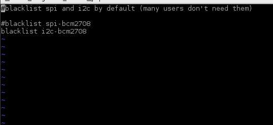
sudo vi /etc/modprobe.d/raspi-blacklist.conf
Then press ‘i’ to be able to insert characters
Add ‘#’ in front of ‘blacklist spi-bcm2708’ to comment it out
Press ‘i’ again to exit insert mode
Exit the editor with ':wq’
It should look like this:

Then turn off your Raspberry.
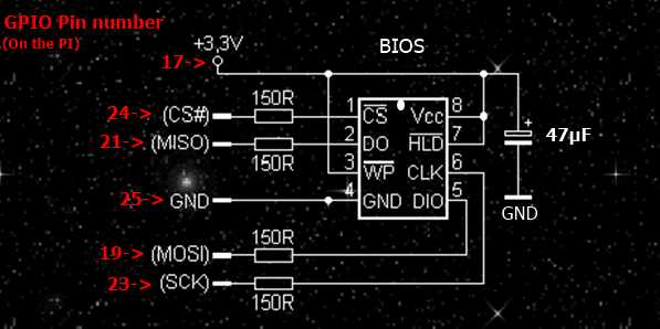
Solder the wires, resistors and capacitor to the DIL socket, like in this schematic:

Connect to the GPIO pins:


Before any flashing, image file must be checked for sanity. Any ready-to-flash image file for Intel-based boards must have >this< format, and conformity to it must be explicitly checked.
It can be done manually using HexEditor (just look for 0x0FF0A55A signature on offset 0x10) or with UEFITool, that either shows opened ROM file as “Intel image” with Descriptor and other regions in it, or shows “XX region has intersection with YY region” message (common bug in descriptor configuration of modern Gigabyte boards).
Another requirement for any UEFI BIOS for any X86-based platform is that Volume Top File must be located so, that it’s last byte is also the last byte of the image, that is why ready-to-flash images with kilobytes of 0xFFs at the end are suspicious.
The size of image must be the same as the size of SPI chip.
Make sure everything looks Ok, insert the BIOS chip into the DIL socket, then power on the Raspberry.
Copy 1.rom to your Raspberry, i usually just put it in /tmp
On Linux what you type in a teminal is case sensitive.
To erase the chip (not needed on most chips) run:
sudo flashrom -E -V -p linux_spi:dev=/dev/spidev0.0
To begin flashing run:
sudo flashrom -w /tmp/1.rom -V -p linux_spi:dev=/dev/spidev0.0
If it does not detect the chip, may be not configured “raspi-blacklist.conf” try running these commands:
modprobe spi_bcm2708
modprobe spidev
if it still doesn’t work, check all the connections, make sure it’s supported by “flashrom”.
When it’s finished flashing and verifying:

Close the terminal, shutdown the Raspberry and remove the chip carefully from the DIL socket, put it back in the motherboard, and power up.
Note: When reprogramming a chip this way, you may lose the NICs MAC address, this can usually be restored in different ways, provided you have it somewhere, it can be a sticker on the MB or if you have a router it could still be in the log files.
Some information regarding the JSPI1 header on MSI motherboards.
I have now tested it and can confirm that it works, what i did was disconnect the Power and remove the battery, then i connected the GPIO pins, also 3.3v from the Raspberry to the appropriate pins on the motherboard, powered on the Raspberry and flashed it.
There is useful information about the JSPI1 header here.
Video version of this guide by "tpc010"
EDIT: Updated 07/11/2015
Thanks to “CodeRush” and “tpc010” for contributing valuable information to this guide.
|addpics|242-1-ddde.jpg,242-2-c07f.jpg,242-3-18d3.jpg,242-4-e73f.jpg,242-5-0b93.jpg|/addpics|