Here it is. https://www.dell.com/support/home/us/en/…alienware-17-r5
If there is an extractable firmware 4mb i will reflash all that bioses. And also will check the last one in 30 minutes.
Again, 4MB have nothing to do with EC FW, so I wont be giving you anything 4MB in size. Thanks for link
Yes it may be smaller. I just said because dump from aw 17r4 of this ue2 chip was 4 mb.
No, you are incorrect there as well, I tried to explain above and this will be last time since you seem sure you know more about BIOS than I do. Please listen, today is not my first day 
EC FW on any Dell/Alienware is not 4MB, that is FD/ME and other BIOS contents, this has nothing to do with EC FW and never does. EC FW goes into a 128Kb-1MB chip only.
I checked the stock BIOS EXE, this contains a 10.3MB BIOS region only (Which does contain some EC FW contents @256KB), two flash tools (32/64) and two driver files.
Also there is a batch file command line entry and a batch file info text for user to be sure to update to certain Command center version before using this BIOS or Alienware FX lights wont work
There is no HDR file in this EXE, so not sure what you thought you came up with on page one or how you got there but it’s not HDR
Did you locate the 1MB or less flash rom chip yet? What size is the chip you erased, that you tried to put the vina fix contents onto?
And speaking of that again, never mind I guess, saying that out loud reminds me you are stuck on this 4MB thing, so if what you thought was EC from Vinafix was a 4MB file then you’ve not tested any EC FW from Vinafix either, since no EC FW is anywhere near anything close to 4MB (That would be FD+ME etc)
Please locate the less than 1MB flash rom chip on this board and dump it’s contents for me, since I know this is not what you’ve been discussing when I mention EC FW and to dump it, otherwise you’d have never tried to program anything 4MB into a much smaller chip and expect it to be possible.
Also, you are looking at the board always, give me this chips ID too, in full. Otherwise, this is last time I want to discuss EC FW
There is only one 1mb chip on the board and i already said that it was empty. It was UE2 i also attached photos of the motherboard with all firmwarechips couple posts ago. UE2 chip size is arround 1mb. It;s regular 25 sop8 chip. And there was nothing on it.
This bios is working. (#38)
Thanks for clarifying the size. Sorry, I had not downloaded any images from this thread, I didn’t notice any in zip so probably didn’t grab them.
I wanted the exact specifics and the full model ID from the EU2 chip. I checked the linked image, it’s too small and not specific enough on each chip, to see any BIOS chip ID’s
Yes, I know you said there was nothing on there on the UE2 chip, which I already told you was surely incorrect, but it’s now erased, so nothing we can do… again.
Thanks for report back on BIOS, I will use that as my base. Can you dump the graphics card vBIOS with GPU-z? If not, don’t worry about dumping with programmer, that is possible but I know it’s a hassle to do, unless you already have those heatsinks off there.
The 1mb chip id is GD25Q80
Video bios attached.
1080ALIENWAREes.zip (151 KB)
That’s GPU-z dump, correct? Thanks
If you do happen to have heatsinks off any time in the future, dump that chip for me with programmer to, if you do have them off and remember.
I can update that to latest vBIOS for you too, but this ideally would need to be done with programmer, since it’s laptop, in case recovery is needed you have everything apart and can quickly reprogram back in original dumped vBIOS. (file already updated on my end, from Apr/2017 to May/2018)
Anyway, thanks, I will look into this and the vBIOS inside the main BIOS, to see if I can figure out what’s causing the LCD thing you mentioned. you never answered me on my questions about this at post #38 >>
Please explain more, how/where do you see this when using the 15" LCD >> The laptop thinks it’s alienware 15 r4 << Where do you see this? And same >> gpu changes to Maxq version << Where do you see this
Are those changes OK for you, I mean you don’t mind if I found the reason for this, and change it to be same for 17" as with 15", would that be OK with you?
The vbios i corect i also flashed couple other vbioses there but reverted to stock one as it thermals and performance are the best for now. If You have a mod one You can give me it and i will wlash it by nvflash from windows.
I replied You in post #39 : If i will connect 15’’ lcd it will change the model name to aw 15r4 on first bios page and it will also change gpu to MaxQ in device menager in windows.
I dont mind ift will be 15 or 17 model in bios.
I think laptop detects lCD’s edid and set up bios and ec controller to mathch AW15 thermals. Any way i checked them both 15 and 17 and gpu performance is 100 identicall may be even more stable on maxq version but no loss in FPS during testing. Thats because AW 15R4 has smaller heatsink but dell use same boards on them from Alienware 17 R2 they only differ by cpu and gpu model but You can fit any board in any laptop You want all connectors and mountig holes are the same.
Also this VBIOS is fully unlocked by core and memory. Only voltage adjust is hiden.
The updated one I have only updates GOP/EFI Module in the vBIOS, so would only possibly help if you use the card in UEFI/Secure boot mode.
Also, I am unsure if this kind of edit breaks the BIOS for this series or not, if they do signature check on 10xx cards then it probably would fail. But, at least you have programmer and could recover easily, I will send the file if you want to try it.
Thanks, I think I missed your comments about where it’s showing you the model name of the system and vBIOS. What shows in those locations when using the 17" Maybe this is not the 17 R5 model, but really is the 15 R4?
What is “MaxQ” version, is that some type/version/model of card for these systems? I do see here, mention of MaxQ, but with different deviceID/subsystemID being mentioned (1028=Dell / 10DE=Nvidia) https://pci-ids.ucw.cz/read/PC/10de/1be0
Your vBIOS shows as 10DE-1BE0 - E2915 SKU 10 - in the dump
What is the resolution of the 15" and 17" panels? And, are you connecting both using the same cable during your testing?
Are you always using “Optimal” (ie “Restore Defaults”) as a starting point in the BIOS? If not, please do, I see some settings options are missing/not loaded properly on fail-safe.
In order to try and fully unlock this BIOS, I’ll need you to test a few different things for me and report back, across a few BIOS test series.
This lets me know which way of several, will enable certain things that are currently hidden from you, or which ways to move/swap menus etc. Once done with a few of these rounds, I’ll be able to do full unlock
For now, let’s check a hidden setting and a menu swap as initial tests.
Setting goal >> Battery Charge Configuration (near bottom of page) - let me know which if any of these BIOS you see this option, stop and no need to test further once you see this option
Do not be concerned if settings are missing or do not function for this, only checking if it makes visible to you or not. Please test in the following order, stop testing once you see the new setting option, then let me know which BIOS
And yes, I know this is similar/same as the “Express Charge” option a few settings up, my goal is not to unlock this setting for you, although that is a possibility to leave or switch later if you want, the only goal here is to see what all methods are required to make visible a hidden/suppressed and grayed out option for any setting.
1. SetOnly
2. SetBCPU
3. SetBCPS
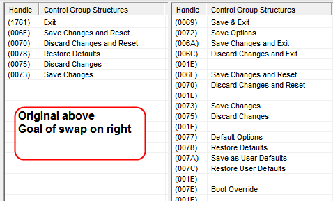
Test Goal >> Menu Swap (Exit >> Save & Exit) - same as above, once you see the new page stop testing. You will see new Title “Save & Exit” instead of Exit once swap is correct. But below is image of both, so you can see the possible setting differnces
If page is blank this is OK too, let me know, but don’t worry about it. I did not spend time to unsupress or change anything here, so options may be missing or all blank, only goal is the menu swap itself, rest to be sorted later.
Additionally, you may see both Exit and Save & Exit, all OK, just let me know what you see and which BIOS you first see Save & Exit.
If none of these show Save & Exit, that’s OK too, only means more advanced method is required, which I did not do yet in case these quicker methods work first.
1. AMITOnly
2. AMITBCPU
3. AMITBCPS
http://s000.tinyupload.com/index.php?fil…863131055987597
Thank You for dumps i will check them soon.
The both 17 r5 and 15 r4 use same boards. Only heatsinks are smaller in 15 model. According to heatsink i have on my i’ts 17 r5 also case screen etc. Tha panel i was using for testing was 15 and 17 edp lcd with Full Hd resolutin. I have only one LCD cable for this laptop and it’s what the laptop came with. Both lcd’s work. When I swap them and power on it will turn off and on the next power on it will show model 15 or 17 depending to what lcd is connected. I think that firmware can be from aw 15 because when i lunch built in diagnostics it will show Dell Alienware 15 R4 bios ver. 0.2.5 etc. even when the 17’’ screen is connected. I dont know how it swap the gpu model but i think vbios in it contain 2 cards. Maxq version is a cut of normal version of gpu but in this case the performance level is same because i think it wasnt set up at this firmware which clocks each card should run to prevent overheat.
You’re welcome, I’m sure we’ll get the BIOS unlocked. Since both models use same board, it’s very possible this board was either meant to be the 15 R4 model, or someone put R4 model board into R5 shell?
That makes sense to me when you say with xx monitor all this stuff works correctly. However, we may just need to find this stuff in BIOS/vBIOS and adjust it too, hard to say.
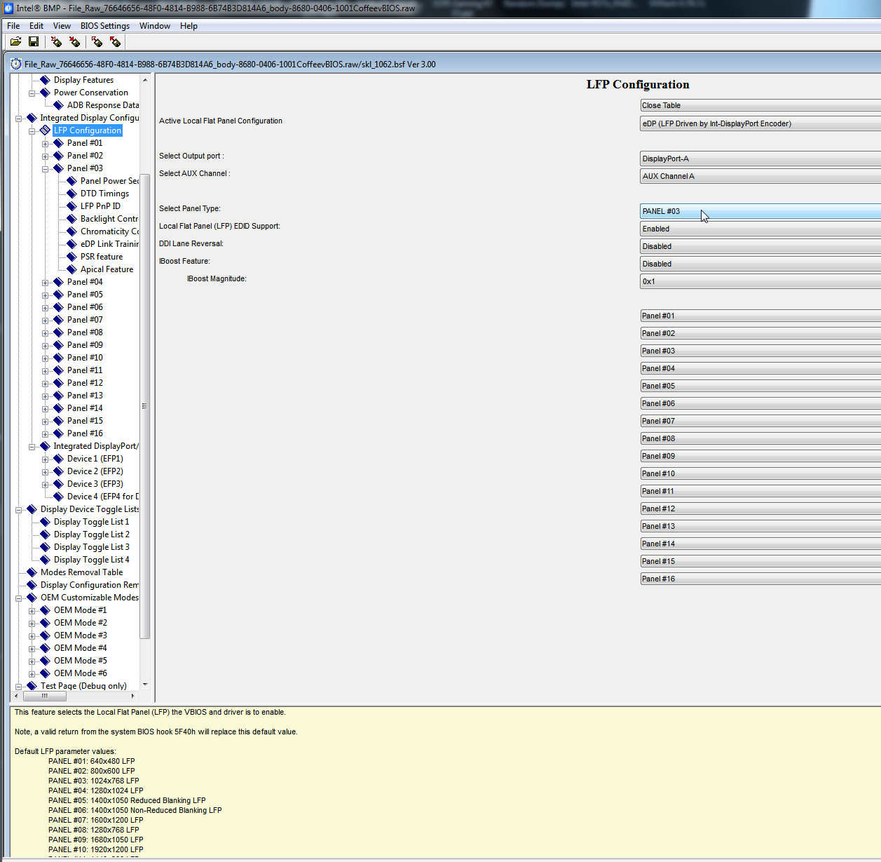
What is the actual screen resolutions on each. Currently, the in-BIOS vBIOS is set to using panel #3 as shown in below configuration image, this is why I’m asking. I can change this to match the 17" and see if it changes anything on your end.
Interesting about the diagnostics, I may be correct then it what I mentioned above, this is meant to be an 15 R4, someone put this board in R5 shell, or Dell sent to tester that way, just as randomly configured system for testing something.
Can you ajust fans tables in bios? I can only see the fan performance mode in my current state it’s off but fans works same if it’s emabled. Also usb c device has an error 43 i device menager also laptop does not recognise any usb hub if i will put there any usb device.
I can’t remember, I’d have to dig around and see about the fans, usually there is some adjustable things related to this such as temps/thermal trip points and certain fan speeds.
* Yes, << This kind of thing is there in hidden section I will enable for you once we get there
Still waiting on report from test BIOS sets at post #50, and waiting your answer to my questions at post #52
Ok! I tested dumps!
On each first dump from each folder i can see diferances!
Battery swap dump adds more settings to battery charge mode.
Exit swap dump swaps menu on first dump.
Both panels i used on this laptop where Full HD panels 1920 x 1080
Thanks @code9523 - Please confirm
1. SetOnly << This one you can see new setting? >> Battery Charge Configuration
And this one
1. AMITOnly << You can see new Exit Menu?
Also, thanks for the panel info, are you 100% sure that is the max resolution on each? Did you set them up, and check in windows to confirm? If not, can you please check to confirm.
That is weird if both are 1920x1080 panels, since vBIOS is configured for 1024x768. I expected maybe one of them was this, probably the 15", and that was maybe why it was working better (Showing proper system model + GFX name etc)
If both are 1920, then I’d expect both would act same, if this vBIOS setting being 1024x768 causing the differences between how they both acted. If they are, then this isn’t what’s causing that to happen.
We’ll have to test what happens if I set this correctly to the proper value! Never mind, see below for the table, there is no value for 1920x1080  so we can’t test that.
Due to this, please test each panel and check in windows with drivers installed, what is the max resoltion you can set each panel to.
LFP parameter values:
PANEL #01: 640x480 LFP
PANEL #02: 800x600 LFP
PANEL #03: 1024x768 LFP
PANEL #04: 1280x1024 LFP
PANEL #05: 1400x1050 Reduced Blanking LFP
PANEL #06: 1400x1050 Non-Reduced Blanking LFP
PANEL #07: 1600x1200 LFP
PANEL #08: 1280x768 LFP
PANEL #09: 1680x1050 LFP
PANEL #10: 1920x1200 LFP
PANEL #11: 1440x900 LFP
PANEL #12: 1600x900 LFP
PANEL #13: 1024x768 LFP
PANEL #14: 1280x800 LFP
PANEL #15: 1920x6108 LFP
PANEL #16: 2048x1536
SetBCPS.bin Yes there are more settings of battery. Even custom charge avaliable.
AMITBCPS.bin I can see nev exit menu.
All pannels are FHD 1920x1080 i don’t have any other panels. I confirm that their max resolution in windows is FHD 1920 x 1080 .
Thanks for confirmation x3! New test BIOS coming soon, unlock more/all of BIOS. See, good thing I asked, you said “First BIOS from each” which is BIOS #1 as I asked about, then you gave reply above about not BIOS #1 from each test.
That’s why I asked, please be specific, it’s important as to which method is needed for unlocking certain things.
So, to be 100% sure again, these BIOS no change visible, correct?
1. SetOnly
2. SetBCPU
-----------------
1. AMITOnly
2. AMITBCPU
And I want to send you test BIOS with vBIOS set differently, but unsure what to choose since 1920x1080 isn’t a choice there which is pretty odd! I checked, the BIOS itself also does not have this option in it’s list of panel resolutions 
I will see if updated vBIOS only has same settings too. Maybe send a secondary vBIOS test BIOS with updated vBIOS/GOP too just to see if any better/different for you.
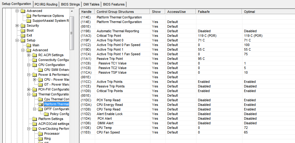
You asked a while back about Fan setting in “Performance Options” in Advanced page. What all can you see on this page? Please show me image of this page, thanks
I havent test other as You said before!
I flashed by your instruction and when i saw diverances i stopped flashing.
I flashed SetBCPS.bin and AMITBCPS.bin as you said if i will see menu swap and diverances i don’t have to flash other.
@code9523 -  - Please always test the BIOS as I listed for you, in the order I specified, this is required process, in order! Please test in the order I mentioned, and let me know which one you FIRST see the things I asked about for each set.
I did not say test any BIOS you want, and then stop when you see changes, I said “Please test in this order” then stop when you see changes, and I gave a specific order with BIOS numbered and named.
Now, please go back and test in order, since we already know the last ones from each test work, no need to test them. Test BIOS #1 from each, if changes are shown there, then you stop, no other testing needed.
I made BIOS 1, 2, 3 and if BIOS #1 works, then 2/3 not needed, for each set. Different changes in each and we want least modification as possible, this is why the order is specific and this test process is required.
Plus, sometimes BIOS 2 or 3 might cancel changes in BIOS 1, this is why 1 test before 2/3 etc.
I cannot continue process on my end until I have results from all BIOS testing, since you did out of order, I now need you to test BIOS 1 and 2 from each also.
Originally you might have only had to test one BIOS, or two, maybe three, but now you must test them all, unless changes are visible on BIOS #1 from each