Bricked Dell Optiplex 5060 + CH341a + SOP16 > Alive again

Looks like a perfectly fine image, ME unpacks fine.

How did you dump your firmware? Anyway I’d recommend to dump what’s in the chip now just to have a look what went wrong.
According to your description
“rebuld the Image and then push it with fptw64.exe -desc and fptw64.exe -me back to the SPI.”
That should work with a complete and properly rebuilt image, too, without size warning.

Can you attach the image you flashed and / or the actual content of the chip?

i dumped it with fptw64 -d command

I added the two links in my first post.

Thank you for your help!!!

cse_image_FWU_Base.bin, cse_image_FWU_Full.bin are files for ME- firmware updates made with FWUpdLcl64

The ‘real’ thing / the correct firmware (if you didn’t work on a region only) would be outimage.bin
(Not your bios in the example, it’s a lenovo with firmware divided onto two chips, that’s the reason for generating 3 outimage files.)

ftpw64 flashes everything you order it to, but update files do have a different structure than a ME region and don’t work. In addition they have a different size.
And they don’t contain a flash descriptor but of course ftpw64 will write it there even if it’s about 3000 times the size.

(Don’t work on a region with FIT, always use a complete firmware image- just in case)

The settings needed for vpro/AMT are:
“Intel (R) ME Kernel” - “Intel (R) ME Firmware Update”
HideMEBxFwUpdCtrl value=“No”

“Intel(R) AMT”
AmtSupported value=“Yes”
NetServicesSupported value=“Yes”
MngAppSupported value=“Yes”
MngAppPowerUpState value=“Enabled”
AmtIdleTimeout value=“0xFFFF”

“KVM Configuration”
KvmScreenBlnkEnable value=“Yes”
KvmSupported value=“Yes”

“TLS Configuration”
TlsSupported value=“Yes”

Hi. I see an outimage.bin and outimage.map in the directory from the FIT Tool. You mean i simply flashed the wrong binary?

Tonight i’ll order the nescassry Equipment for flashing the SPI

  1. KeeYees SOIC8 SOP8 Test Clip für EEPROM 25CXX / 24CXX + CH341A 24 25 Serie EEPROM Flash BIOS USB Programmer

  2. SOP-16 Clip

Yes, unfortunately.

ftpw64 can (afaik) extract regions from a complete image with proper flash descriptor, but if an “unstructured” file / a file without recognizable structure is given, it will simply flash it to the region chosen in the commandline.

So a ftpw64 -desc -f outimage.bin will indeed flash the descriptor to the addresses stored in the FD, same for a ftpw64 -ME -f outimage.bin, that will flash only ME region with the corresponding region og the file given in the command arguments.

Open your own dump and outimage.bin in UEFIToolNE, compare the structure.

At the moment i see Problems to Flash the MX25L25673GMT SPI Chip at all https://winraid.level1techs.com/t/problems-flashing-mx25l25673g/34664

Did someone successfully flash a MX25L25673GMT with a SOP16 Clamp and a CH341a programmer ?

Update: Maybe NeoProgrammer 2.2.0.10 can help

Today i received the CH341A Programmer and the SOP-16 Clip. The motherboard has to be dismount from the pc chassis.
In the next step i’ll have a look at right pin assignments as there are many combinations possible.

Here my Setup / Wiring

Update:

I wasn’t able to connect to the SPI IC. I used NEOprogramme and flashrom under Win10 (Admin). I switched drivers, MOSI / MISO Connection and even connect the PSU to the motherboard. No connection to the IC.

My next step is to install Linux (Ubuntu) beside my Windows and try again. => FAIL !

=> (within the next days) Will this fail too, i dissolder the SPI IC and solder it directly onto the back of the CH341a Stick.

In several threads i see problems with the SOP-16 SPI ICs in combination with CH341a. Is there anybody who can confirm that this possible at all ?

Best Regards and thank you

Florian

Last Update: I found another Dell Hardware with a SOP16 winbond25025… SPI IC. I cannot connect to this ic, too. So maybe the CH431a or the clip has a bug. Or. It is simply not possible.

Another Day, another try => Success. :sparkles: Connection to IC established

Will post details soon

1 Like

Good luck!

Ok. Here the detail. Finally i have a connection with the MX25L25673G.
I use AsProgrammer (https://github.com/nofeletru/UsbAsp-flash/releases/ in the latest version with the included driver.

I made four dumps with my Win10 Laptop. Every Dump has a different MD5 Checksum :pensive:
So i cannot say that i have a valid backup from the SPI IC. At this moment i connect the setup to my workstation and will make dumps again.

=> Change to workstation doenst make this better.

This is one of the DIFFs between the two dumps

Maybe someone could answer me the following question:

  1. What could be the problem that every dump has different data within? I dont move the SOP-16. I only click on the Read the Flash Button in the Software. Could it be the situation that the SPI IC still is mounted and connected to the motherboard and interference from other components could disturb the communication to the CH341a?

  2. Could i risk to simply overwrite the SPI content with the outimage.bin with the knowledge that i might not have a valid backup of the spi ?

  3. I wrongly flashed the SPI with cse_image_FWU_Base.bin. Am i right if i say i should found the content of this file somewhere within the dump i made ?

Probably bad contact of the clip.

If you can’t read it don’t write it. You won’t be able to verify a good write, sitting in an undefined state and unable to diagnose it.

Yes. It depends in which order you did use the commands. You wrote
fptw64.exe -desc and fptw64.exe -me

I’d say with overwritten descriptor the second command shouldnt have worked since there wasn’t any longer a valid descriptor to define a ME region? You should anyway have a large area of your bios region in the end of the file.

Hi lfb6,

so maybe i have the dissolder the SPI IC. I had the hope to avoid this step.

Thank you for your help

There are som tricks, like with or without CMOS battery, power attached, not using unnecessary pins, but as written, it’s mostly bad contact. In addition search the forum for this chip,

Just to mention: A file with only FF will have a valid looking checksum, too, and have identical reads. Please check structure with UEFIToolNE.

Hi,
great news ! Summarized: The Dell PC is alive again and INTEL AMT is enabled.

So whats happend in the last days?

After i got no valid results from the SPI IC i decided to desolder the IC from the motherboard (hot-air dessolder with 450° C)
At the samtime i found an defective Dell 5070 Motherboard with a similar 25Q256JVFQ Chip to try and qualify my desolder skills (which are still quite bad)
I put both ICs into die SOP-16 Clip and try to read out. Now i got only FF FF FF Data. On both ICs.
In the next step i ordered some more CH341A Programmers, switched differend drivers and tools.
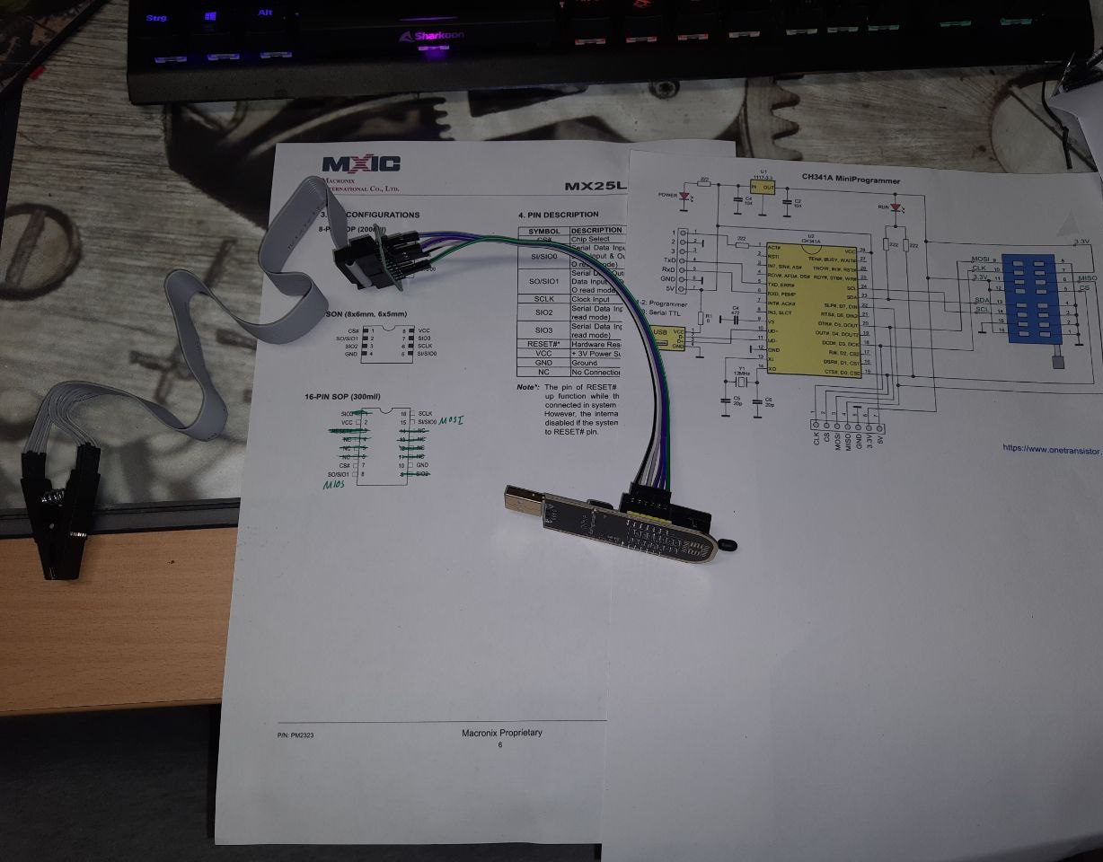
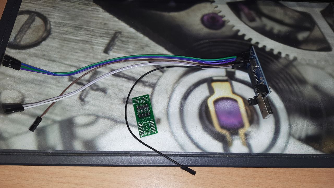
At on point i believed that CH341A and 256MBIT SPI Chips aren’t compatible. So with noting to loose, i solderd the SPI IC to the adapter board from the programmer.

and connected the wires. I used the datasheets from Winbond and Macronix to get a valid SOP-8 to SOP 16 Mapping

PIN SOP-16 PIN SOP-8
7 1
8 2
9 3
10 4

2 8
1 7
16 6
15 5


(Copyright: winbond.com)

it was also quite important to connect pin 1 from the IC to 3,3V (up)

So i soldered only 8 pins from the SOP16 IC

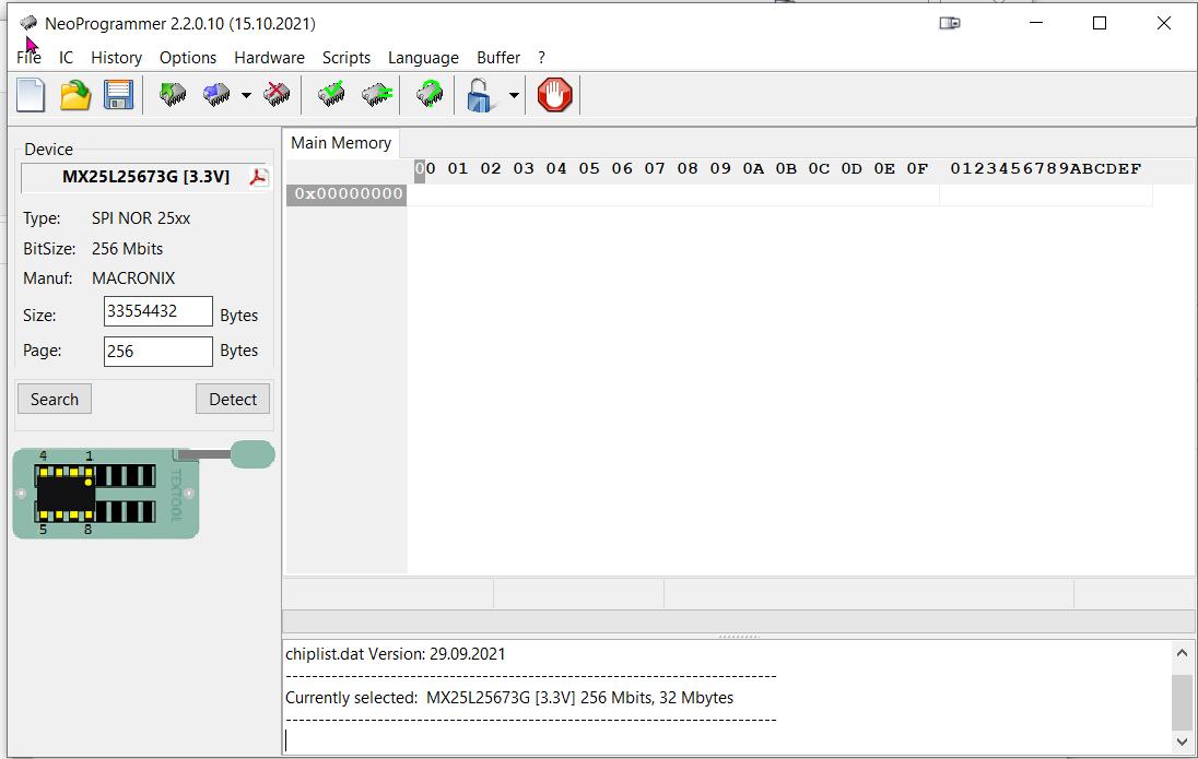
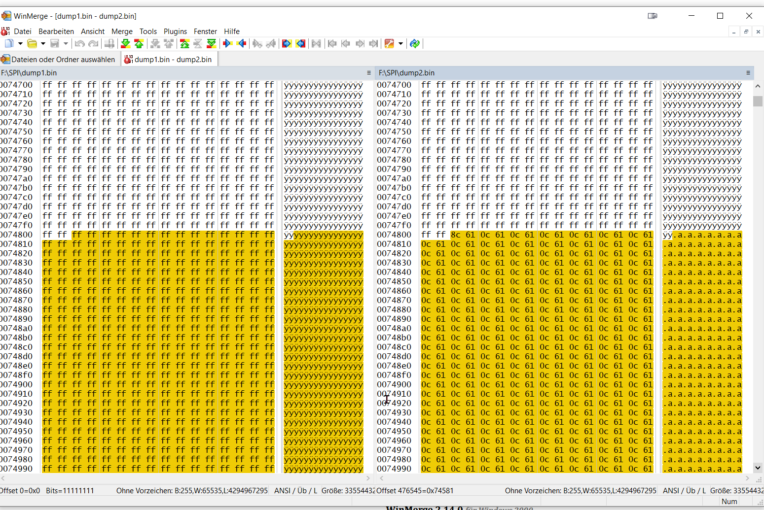
Now i got a valid READ from SPI and same Checksums after severals passes.

In the next step i desolderd the winbond and solderd the MX25Q256 from the Dell 5060.
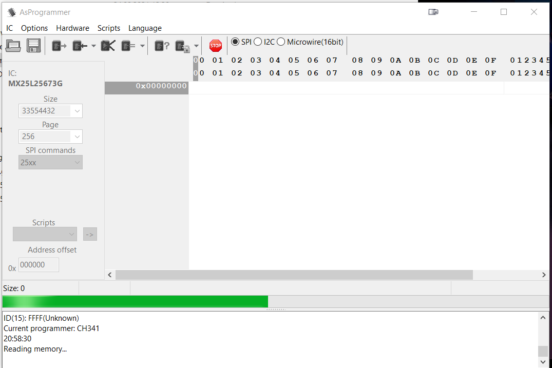
Unlike its Winbond Brother, i couldn’t get identical checksums. I tried several tools and drivers again. Nothing worked. i made six dumps. and all dumps differ in a very small area from maybe 100 blocks.

With nothing to loose i erased the whole IC (with NEOProgrammerm which detect the MX25Q256 flawlessly), checked the erase and flashed the outimage.bin.
After the first compare (binanry vs IC content) i got a positive feedback. Checksums identical. (Time to Party :wink: )

Then desolder and solder an the mainboard back again (now i realized that i definitely a new GOOD solder iron), connected the PSU and TADA. PC is booting again… but no Intel AMT

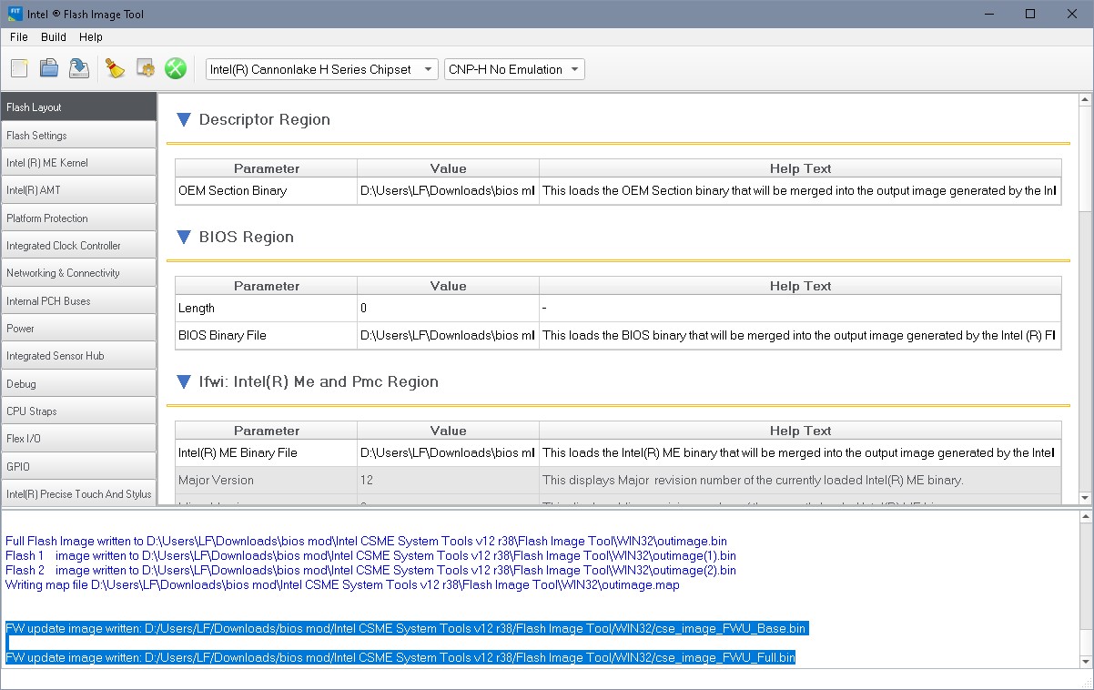
So with the knowledge about UEFIToolNE to validate the Binary from INTEL FIT Tool i made a binary again.

I found a short How-To here an Winraid

  • Turn off PC
  • Add Service Jumper
  • Turn PC on
  • Press F1 when warned about the PC booting into service model
  • Boot into Windows, log in as local admin
  • Run an admin cmd window
  • cd to USB drive.
  • cd E:\Intel ME System Tools v9.1 r7\Flash Programming Tool\WIN64
  • run fptw64.exe -d eastburn.bin -me
  • move eastburn.bin e:\
  • cd "e:\Intel ME System Tools v9.1 r7\Flash Image Tool\WIN32\
  • run fitc.exe
  • load e:\eastburn.bin
  • expand ‘ME Region’ → ‘Confirmation’ → ‘Features Supported’
  • Set the following:
    “Enable Intel (R) Standard Manageability; Disable Intel (R) AMT” = No
    “Manageability Application Permanently Disabled?” = No
    “PAVP Permanently Disabled?” = No
    “KVM Permanently Disabled?” = No
    “TLS Permanently Disabled?” = No
    “Intel (R) Anti-Theft Technology Permanently Disabled?” = Yes
    “Intel (R) ME Network Service Permanently Disabled?” = No
    “Service Advertisement and Discovery Permanently Disabled?” = No
    “Manageability Application Enable/Disable” = Enabled
  • Expand ‘Descriptor Region’ → ‘Descriptor Map’
  • Set ‘Number of Flash Components’ = 0
  • Build menu → Build Settings → untick ‘Generate intermediate build files’
  • File → SaveAs → E:\Intel ME System Tools v9.1 r7\Flash Image Tool\WIN32\eastburn.xml
  • Build menu → Build. Yes to prompt for ‘Are you sure you want to choose the Boot Guard Profile: “Boot Guard Profile 0 - No_FVME” for this build?’
  • Output .bin file will be “E:\Intel ME System Tools v9.1 r7\Flash Image Tool\WIN32\Build\outimage.bin”
  • copy outimage.bin to “E:\Intel ME System Tools v9.1 r7\Flash Programming Tool\WIN64\outimage.bin”
  • cd E:\Intel ME System Tools v9.1 r7\Flash Programming Tool\WIN64
  • run fptw64.exe -f outimage.bin -me MAKE SURE YOU INCLUDE THE -me SWITCH. Answer Y to ‘…fill enough data…’
  • run fptw64.exe -greset
  • pc reboots. Remove service jumper when PC is shutdown.
  • turn pc on. It may restart a few times, then it will boot OS.
  • reboot PC this time boot into the MEBx menu and configure settings with:
    MEBx login → default password is ‘admin’, change to ‘Jacobs5%’ (no quotes)
    Intel AMT Configuration → Manageability Feature Selection = Enabled
    User Consent → User opt-in = None
    Opt-in configuratuion from remote IT = Disabled
    Network setup → Intel ME Network Name Settings → Host name = (blank)
    Domain name = (blank)
    Shared/Dedicated FQDN = Shared
    Dynamic DNS update = Disabled
    TCP/IP settings → Wired Lan IPv4 Configuration → DHCP mode = Enabled
    Activate Network Access = Y (should change to ‘Full Unprovision’

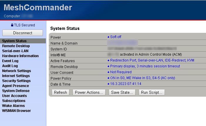
After that Intel AMT with visible within the DELL Bios. MBEX is now accessable via the F12 Boot Menu.

BUT (there is everytime a BUT)
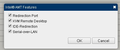
The Intel AMT Console via Web is an READ-ONLY. I can’t even power down / power up the PC.
All the work / the worries / the time for NOTHING ???

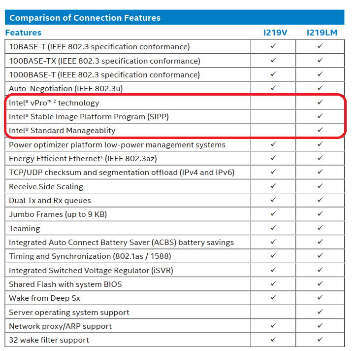
So, maybe the last question in this thread. The CPU is Intel i3 8100. In the Specs i found nothing about vPro capabilities.
Could it be, that it is simply impossible with this processor ? I cant believe it. KVM maybe, but simple, mainboard relating functions like power down / power up should be possible indepented from the processor.

I’m sorry. It’s simply to late here. There is a option to power down / power up.

so actually im trying to get KVM running. Within the MBEX Menu i see no options,
but this website says i have to use a Intel Tool named KVMControlApplication.exe to activate KVM (https://www.thomas-krenn.com/de/wiki/Intel_Active_Management_Technology
This articel was written in 2011. So i think CSME maybe works different. In the Intel SDK linked in the article isn’t any binary file.
Maybe somebody has a advise for me.

greetz,
Florian

big thanks to lfb6 !!!

Thanks for the feedback, congrats to a working machine :slight_smile:

Regarding AMT settings- you cited the ME 9 settings,they change from version to version, your ME 12 has slightly different settings (see #8)

For KVM (AMT) NIC, chipset and cpu need to have vpro capability. As mentioned i3 don’t have. Earlier this was clearly stated in the properties, now possibly some marketing i… found out that it’s better to no longer mention capabilities a cpu doesn’t have, thus leaving it unclear if the capability was forgotten or doesn’t exist.

Provisioning can either be done by the web page, a usb stick with a bin settings file, Intel software or via a trusted server ot other software. I’d recommend Meshcommander if you’re not in a large environment with existing management software.


me2

Did everything as per above, but MEBx (Ctrl+P) still not active, neither in F12 menu.
CPU:i5-8500

What machine?
What chipset?
What NIC?

Post/attach the original and the changed firmware.

  1. Dell Optiplex 5060
  2. Q370
  3. integrated (Intel i219-V per spec)

Unfortunately:

1 Like

Thanks for the prompt and comprehensive replies, spec. screenshot is very informative :+1:

Just to clarify, with Optiplex 5060 non-KVM AMT is possible, but KVM AMT is not possible because of the type of integrated nic?

Can a KVM AMT compatible nic be installed into a spare PCIe slot?