Hi, I am looking to flash a new BIOS into my MX25L25673G Chip. The reason is due to a failed bios update issued by my GIGABYTE Motherboard which does not have a BIOS Flashback functionality.
I have the CH341A Pro and currently wondering what would be the best Software to get this flash to work.
I have already attempted Flashrom following the steps indicated in the guide below and the terminal reports to me that the whole process worked, but when I install the chip back on the Motherboard SPI Socket nothing happens. I have also ordered new BIOS chips of this same model number in case the current one happened to be faulty for some reason, and the behavior is the same with the new chips as the old one.
Flashrom Guide: [GUIDE] The Beginners Guide to Using a CH341A SPI Programmer/Flasher (With Pictures!)
Looking forward to your suggestions.
Thanks!
@hoyzon - Let’s ask @code9523 what version software he used for your same MX25L25673G chip, I see he mentioned programming this exact chip Here
I have no experience with Flashrom, so I can’t help there. But in general I would advise trying 1.30 or 1.34 version CH341A software from this package, with chip ID MX25L25645G or MX25L25635F
Also may work if you use the 1.40-1.31Free version, you don’t choose ID in this, just chip size, then dump and see what if you get a good dump or not.
http://s000.tinyupload.com/index.php?fil…695330485827902
Or ASProgrammer and chip ID MX25L25635E - https://github.com/nofeletru/UsbAsp-flash/releases/
Hopefully you made a backup of the chip before you attempted any erase or writes? If not, you will need to find your LAN MAC ID on sticker on board, usually near LAN but can be other places.
This will need put back into BIOS before you flash back in, unless your board stores MAC ID on LAN Chip FW (not sure, since you didn’t mention model)
* Edit, See also this post #169 - user discusses using flashrom and this exact chip - https://slickdeals.net/f/13676402-dell-p…ree-s-h?page=12
It’s about Dell, but maybe those commands will help you with flashrom (or may later or previous he discusses flashrom version used)
@Lost_N_BIOS Thanks.
To give a better context of the issue, here is what happened.
My Motherboard is an Engineering Sample of the now retail model called GIGABYTE C621 AORUS Xtreme.
Back in July 2019 the board was working perfectly fine until I’ve installed the GIGABYTE @BIOS Software, which prompted me that I had an update for the BIOS available in their database. What I thought was interesting is that my ES Board name is GIGABYTE A1X-C621 and the Retail Mode is the C621 AORUS Xtreme. Supposedly the GIGABYTE program identified my board as the retail model and updated to the F1 BIOS. Then, after rebooting the System the Motherboard never worked again, as the Post-Code LEDs don’t light up despite the fact that the board is fully intact and all the fans are spinning and all the components are heating up as you can see in the video below:
https://youtu.be/cm97_YCUAoc
Here is a link to the Backup I have saved prior to the update:
https://drive.google.com/open?id=161DeEX…ZDLlPTKf9LphCCh
-A1XBIOS.bin being the original ES BIOS
-C621AOXT being the Retail MB BIOS from GIGABYTE’s Website.
Hope you are able to help me solve this problem.
Thanks!
ES board should have a socketed BIOS chip in it, usually gigabyte use SOIC8 socket with flip up cover. Does this ES board not have that? Well I guess it doesn’t matter, you know how to program it anyway, just need to find what software is compatible.
But, if it does have the flip up cover and removable BIOS chip in there, it may program easier in a spring adapter directly in the programmer vs programming on-board with SOIC cable
The problem may have been @BIOS in general, or wrong BIOS flashed in, or it’s also possible sometimes retail BIOS does not work on some early ES boards so you have to stay on the ES BIOS and update it yourself with whatever changes you want.
What you describe sounds like ME FW issue. I would program in the original BIOS, or do you not have ANY backups of that ES BIOS? It could be made with any software, just needs to be the original ES BIOS.
If you do not have, you may need to contact Gigabyte directly in email and explain, they are nice and probably will send you ES BIOS for the board.
Ohh, you do have backup, great! Program that back in and you should be good to go. I can update that BIOS with any changes or updates you need  [
[
I am currently having trouble in programming the Chip with the ES BIOS.
So I have tested with Flashrom and ASProgrammer 1.41 with the existing BIOS Chip and the brand new ones I’ve bought from DigiKey and both of these Software tells me that the flashing process worked for all chips, but when I put the Chips inside the SOIC8 Socket and press power on, nothing happens, the board doesn’t turn on at all (as opposed to turning on before, but not posting).
I have also tried the CH341A Software Version 1.34 following the guide below, but in Step 2 when I click on Verify, it returns this error to me: “Chip main memory with the contents are in disagreement”.
Guide: t4175f16-GUIDE-Flash-BIOS-with-CH-A-programmer.html#no_permission_userprofile
The Version 1.31/1.40 Free Version doesn’t seem to show the correct size for this particular chip, only up to 16MBytes where this Chip is 32.
Would you have any more suggestions as to which versions should I try next?
Thanks!
Did you verify the write? If yes, dump that chip you wrote, and then compare in hex to what you wrote, to be 100% the verify is correct.
If it is, then be 100% sure you are putting BIOS into socket correctly, if it’s HOT then it’s backwards 

1.34 error you mention means whatever ID you choose is not working, try another instead, or try with the 1.4/1.31Free I mentioned instead. * Edit - Ahh! I didn’t realize it does not have 32MB chip size option! You’ll have to stick with ASProgrammer, or keep trying with 1.30 or 1.34
But, if ASProgrammer 1.41 verifies OK, and you dump that and manually verify hex match, then write is OK and no need to try other methods (just stick with this one)
Also, for ALL programming. You are erasing the chip first correct? If not, you should, always. Erase, then blank check, then write/verify.
I used TL866II proogrammer with it’s sowtare ver: 9.0 it flash mx25L25673G chip without any issue.
@Lost_N_BIOS Here is what I’ve done so far:
1 Flashed the BIOS Chip using the Flashrom Utility and Linux.
Here is what the Terminal tells me about the Flashrom procedure: 
Next, I saved the dump after the Flashrom Procedure and compared it against the actual BIOS File.
Here is the result of the comparison: 
As you can see, everything seems to be correct, but when I put the BIOS Chip back on the Motherboard, nothing happens, as you can see in the following video I’ve recorded:
Video: https://youtu.be/d4A6t8k3Mlk
Out of all the CH341 Tools, the only one that I was able to Erase > Blank Check > Write > Verify was the CH341A 1.34. But when Verifying, it tells me the same error: “Chip main memory with the contents are in disagreement” despite trying all the different IDs in the Software for that same family of similar Chips.
ASProgrammer 1.41 behaves like the Flashrom tool, with ASProgrammer I am able to Erase > Black Check > Write > Verify > Save the Dump > Compare against the BIOS File > The Chosen Files Are Identical.
So both ASProgrammer 1.41 and Flashrom are the only ones that seems to be working from start to finish, but for some reason that I can’t understand, the Motherboard refuses to react to the BIOS Chip as you saw in the video above.
Hope there might be something else for me to try out and see if works.
Thanks!
Your manual comparison says it all. Your flashing procedure as-is, is fine, no need to flash the chip in other ways. So, this means either you’re not soldering chip back in fully, or correctly orientated, or you’ve damaged a pad/trace and there is some connection issue now with the BIOS once soldered back in place.
That, or something else on the board is friend./shorted and the BIOS is not the issue. What happens exactly when you try to start the board? I am on limited internet, so can’t watch the video right now.
Even without the BIOS chip on the board (at all), something should happen when you press power button, so if that’s not happening without the chip there then there is some other issue
Other possible causes - Damaged CPU (try another, reseat current one and verify no bent pins in socket), some short somewhere, damaged/missing IC, power protection IC tripped and needs replaced etc
It’s also possible you are writing in a bad BIOS, did you modify it? Even if this, it should have something happen when pressing power button, so if nothing at all, see above.
@Lost_N_BIOS So essentially what happens is that the Board doesn’t start at all upon pressing the power button.
I thought it could be a connection issue with the BIOS Chip, so I have inverted one of the BIOS Chips on purpose for a ~2 second period to see if it was going to heat up and it did quite rapidly. So It looks like the Chip is making some form of contact with the SOIC8 Socket.
Before with the previous “BIOS” which ultimately broke the board, the board would start when I pressed the power button, the VRM fans would spin, GPU lights would come up, but there were no Codes on the Debug LEDs, probably indicating that the board was not posting for some reason but it was at least turning on.
Now after my manual Update with the Backup BIOS that I had, the Board doesn’t turn on at all. And that is the same with the latest BIOS from GIGABYTE’s website.
So I am honestly not sure on what is going on. It doesn’t seem like the Flashing is the problem, it looks like it is now something else that is the problem.
So, nothing at all? NO function, LED, fan spin/bump, nothing? If yes, then something else is wrong as I mentioned. Yes, reverse chip will be HOT real fast and can blow trace, or resistors out, so hopefully you did not do that.
Possibly damaged pad or trace during solder, check to be sure all pads are in place with the chip removed and area cleaned off, you should see copper or silver pads (not grey or other colored area, this would mean pad ripped off during desolder due to too much heat, pressure etc)
Check to be sure you don’t see any blown traces coming from the BIOS area, mainly this could be due to your chip reversal. Other than that, there’s really no way to check all one billion resistors, power protection circuits etc without a boardview and schematic, and extreme knowledge in this area.
Yes, nothing at all despite the Power LED which is normally on when you plug in the 24-Pin Cable.
I think I will just give up on this board. It has been taking a lot of my time and resources to try and fix this so I could use it again. I remember trying to contact GIGABYTE last year to ask for their support right after the problem, but instead they’ve seemingly freak out and asked where did I get this board.
So I guess this is the end of the journey. Thank you a lot for your help @Lost_N_BIOS , really appreciate it.
@hoyzon
C621AOXT.F3D it’s not flashable with an hardware programmer,.
To use that F3D file as update package you need first restore the binary backup.
C621AOXT.F3D doesn’t contain unique SERIAL, MAC, ID and stuff.
@noInk Hi. Interesting. How can I do that?
@hoyzon
You need to restore the original binary bios image before it become unbootable and use the F3D as normal update with the manufacturer provided method.
Some board will work even without those info by using the non writable hardware value, some will error on later boot stages duo mismatch.
By what you wrote it seems your won’t even boot.
Probably you can manually copy from the backup the FD|GbE|ME|10GB1| and a fixed NVRAM on the update and use directly that.
I won’t be able to guide you on the process, so, restore the backup prior the issue and update trough normal mean. The update mechanism will do all of that for you.
If the know to work backup doesn’t work anymore that’s another separate issue.
@noInk I think there was a thread where @Lost_N_BIOS said that GIGABYTE already provides the BIOS ready to flash out of their website.
I think all I needed to do was to rename the .F3D to .BIN file and it would work.
In any case I had a previous backup of the Engineering Sample BIOS and that seems to be in the .BIN format and the same issue is happening regardless of which BIOS I flash on the Chip.
Do I need to include anything into the BIOS before flashing? If so that might be the reason as to why the board can’t see the Chip there or react to it.
@hoyzon
Manufacturer usually doesn’t provide UEFI flashable binary by third party hardware programmer. You need to use the manufacturer software to update.
Only once you download the chip content off the board you can flash the binary back without issue.
UEFI bios lack certain entry by design, some entry could be one-time programmed once the board is serialized other may require attestation to work other might auto-generate by request.
Anyway I don’t know why your board doesn’t boot with it’s “know to work” bios.
Are you sure you are using the right chip to boot?
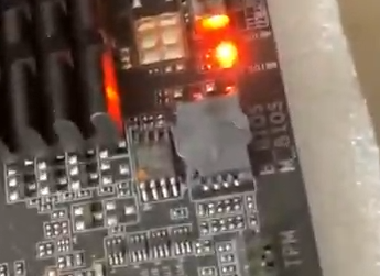
I see 2 chip, one socketed and one soldered.
Does nothing change by removing the one socketed ( open with care ) and selecting the soldered bios trough it’s switch?
is the chip inside the socket aligned or was it ever inverted? do you know it’s pin position?
Does the image come from the socketed? or the red marked?
Probably the B_BIOS is the BACKUP BIOS and M_BIOS is MASTER so be careful.
I have no clue if by switching something on the board will copy\delete or damage the content of B_BIOS
See in that direction something.
If you can read the content without damaging the board try to get the B_BIOS to M_BIOS
@noInk I see. So essentially I need to extract the BIOS off the chip and then re-flash the extracted content into the Chip?
In terms of the BIOS Switch itself, for some reason the Soldered BIOS or B_BIOS never seemed to work before. Only the M_BIOS/Socketed one.
@hoyzon
Essentially you need to restore it’s know to work bios on the socketed chip.
If there an mark like an arrow on the board under the socket and a point on the chip those should match.
Also, check anyway the board location for hardware switch to select the chip but don’t switch the switch… yet.
Gather info about how to force the content of B_BIOS to M_BIOS. If the content within B_BIOS is intact maybe you can boot again.
Backup chip ^ pin one indicator will probably show same orientation as the one in the socket too. But this doesn’t matter, you already know the wrong direction (HOT), so that only leaves the correct direction
Gigabyte BIOS are directly programmable from their website, they are.bin files and are not packaged in anything other than the zip you download. Programming them in work fine, I do it often in testing, with boards from as far back as P35, up until current models.
This works fine but you of course loose board specifics until you correct this, but that doesn’t matter right now. And, in this situation the retail one may not work on this board at all programmed in or flashed in with Qflash/EFIFlash ect.
But, your originally dumped BIOS does not work back in their, so there is some other issue as I mentioned.
Soldered BIOS may not be compatible with your current CPU, it may only work on certain early ES etc, since this is an ES board.
It may be even earlier one than the backup you made, which as you expect should work once programmed back, thus some other issue.