Yes, I did correct that yellow-orange swap. And I tried flashing again, but I still got an error. If I may have damaged my chip by doing this, they I may have already damaged it. x(
Okay I will try a couple of things, thanks for the ideas
Yes, I did correct that yellow-orange swap. And I tried flashing again, but I still got an error. If I may have damaged my chip by doing this, they I may have already damaged it. x(
Okay I will try a couple of things, thanks for the ideas
Don’t think you damaged your chip.
CH341 has some advantages since it’s simple and kinda ‘stupid’- it doesn’t check too much (anything?), it just does ‘something’ and works with many programs…
So if you’re aware of the caveats and check for them, it may solve some problems.
Samsung Notebook, SIO3 by design on GND, TL866 doesn’t work
CH341 still works when IO2, IO3 GND disconnected
Did you try to disconnect yellow and orange (and maybe brown)?
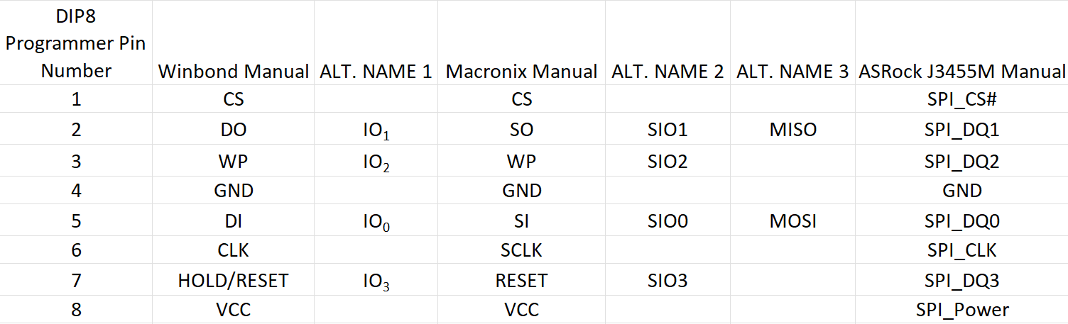
Just want to post an official clean table of all the equivalent names of the pins for clarity.
I was busy and I had to go AFK but I will try new things. I have already attempted without the yellow & orange pins and it does not work at all. I will have to try with a “dumb programmer”.
I will keep you updated
I tried without the yellow/orange pins and with/without ground
and I was able to write a bunch of 00’s into the chip but not much more.
I also tried the ICSP connection, and it ended up being identical to removing orange/yellow (Hold/reset + Write Protection) because I am not able to short them into VCC as the xGecu says.
I also dont have a 30P capacitor on hand to connect between MISO and ground. Which is why it ended up being identical to what you proposed.
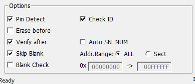
I was able to “stupify” the xGecu by disabling options like
“pin detect, verify after, check ID”
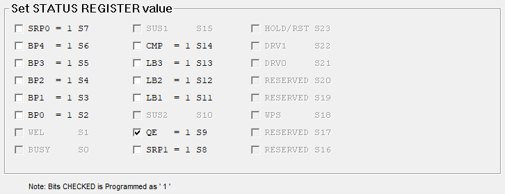
I posted in the xGecu Forum and some guy there has a printer with the same chip, and he says that his chip has a lot of status Register values = 1 (specifically LB1, LB2, LB3), and he says that these values set to provide “advanced write protection”. Something like that. He says he has the same issues with the chip on his printer…
My status register just says
But the problem is that I cant even read/write the thing properly so who knows.
I don’t know if the reading of the Status Register is even reliable or even a relevant information. But it is an interesting point.
The only thing I have been able to do successfully so far, I believe is erasing the chip lol.
Maybe I can buy a new chip with pre-flashed bios in it and just solder it onto the board. I will order one of those now as a “last option” since it takes a while to arrive anyway.
Do you know if this is possible?
I can desolder this strange chip that cannot be flashed and put in a new chip, but I was wondering if I could use the SPI header to create an adapter and just have the bios be read from there
something like this, but it on top of the BIOS_PH1, that way it becomes removable like a the DIP8 packages.
It could be an interesting mod
There are easier solutions (didn’t check measures thouroughly, they exist fitting for your chip):
Good news, I have a CH341A now and I can try doing what the original poster did. I will also connect pins 3 and 7 (Hold/Reset + Write protection) to motherboard ground as the original poster did.
I will report back with update.
UPDATE.
ABSOLUTELY NOTHING worked. I gave up on this pin method.
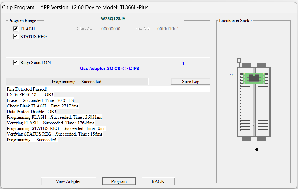
I simply Desoldered it the old fashiond way and I put it into an adapter and I was able to flash it with absolutely no problem!
At first I thought that the pin 3, 7 was just my mistake but it seems that the documentation on this thread has some contradictory layouts for the pins.
It simply takes too much effort for me to figure out what is going wrong.
It would be possible to check the header layout with a multimeter.
This way you could differentiate if it’s really a difficult board or if the header layout of this specific board is different.
I want to say this pinout works on my z270 gaming k6. I grounded WP and Hold lines to the ground pins on one of the usb 2.0 headers. I also found I needed to set the bios reset jumper to clear. Works a charm now!
Was your power supply connected to the motherboard and switched on or off?
Power supply unhooked. Cmos reset to clear. Gotta jump a pin from the header to ground (I used one of the usb 2.0 headers ground pins) worked aces aftet that. Oh and at least with my qtj1 I had stability issues under heavy stress testing if I didn’t cap the chip to 130A. Took me forever to track that down. If you can’t figure it out bump this and I’ll try to figure out the pin to ground when I get up. It should be in this thread though!
Well I actually tried EVERYTHING on a ASRock Z370 Pro4.
+/- PSU +/- CMOS Battery +/- IO2-to-IO3 (WP-to-Hold) pin crossover +/- RSMRST#-to-GND +/- CLRCMOS pin shorting +/- “Ignore Chip ID” setting on XGecu Pro flashing software.
The farthest I ever got with this was being able to have XGecu give me “Pin test passed” and getting a correct chip Identification. I am also able to read the ROM by removing “Chip ID verification” during the reading process. But once I save that ROM and try to open it with CoffeeTime 0.99, the latter will say “Corrupt ROM image”.
So I gave up on that “BIOS_PH1” method. I did the good old desoldering and reading method and it works perfectly.
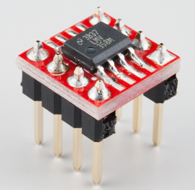
I am now installing a SMT socket from adafruit as pointed out by user “lfb6” and that way if I ever change the processor I can also re-enable Intel ME if I want to.
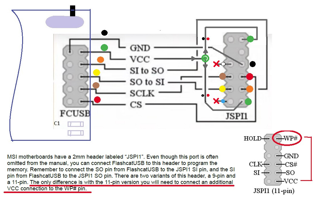
The IO2-to-IO3 (“WP-to-Hold/Reset” or “SI-to-SO”) pin crossover point might sound like nonsense, but I was analyzing all of the images posted on this his thread and some of them do have those pins switched. And then I found this image from an MSI board with a similar header from the following thread MSI JSPI1 Firmware Recovery (Flashcat / Raspberry Pi) | TechPowerUp Forums
MSI calls it “JSPI1” instead of “BIOS_PH1”, and you can see that they also do mention this crossover. So, I tried that too. Just in case you were wondering. The people here that say they got it to work, I have no idea how. I even tried that CH341A junk thing and I tried various flashing software programs. The whole thing was just a total waste of time for me unfortunately ![]()
But the good news is that simply desoldering and resoldering works fine. I just don’t like the process since I am not the most experienced so there is some risk involved. But with this SMT socket everything should be fine.
I cannot comment on the amperage but thanks for the heads up, if I run into any issues I will keep it in mind.
And Just a heads-up for you, when I was using the BGA-1440 mod with ME Corporate Cut, I noticed that whenever I turned the PC off in Windows 11 Pro, it would simply act as though I clicked on Restart. It was extremely annoying. I remember having fixed it but just enabling all of the C-states in the BIOS. I didn’t look into it any further.
–UPDATE–
I just launched my QTJ1, only to my mod worked perfectly but I didn’t flash the version with Re-BAR support…
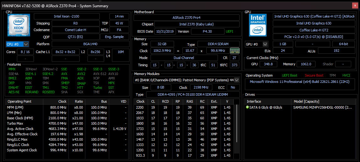
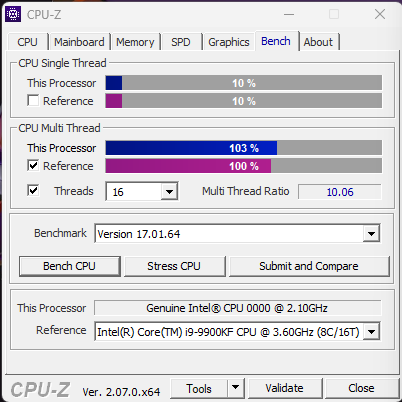
Then I ran the CPU-Z benchmark again and bam. I got 9900KF performance without a problem at an all core boost of 47 and uncore ratio of 43. I didnt even set those to 49 or 50 like on the real 9900K and I still got the same score. The entire problem was the current setting. The CPU voltage is set to positive offset “auto”.
The fact that you have that 130A limit may be thermal throttling. Mine is actually a “Comet Lake”, we seem to have the same chip though, so this is strange. The only sad part for mine is that the chip wont even reach RAM speed of 2666, it only works at 2133 (4 DIMMs), which is a bit pathetic, but maybe I can tighten the timings later. First, I will try to do the Re-BAR mod… Here is the proof:
I think you should be able to max out the current settings (with very good cooling). Im using the latest microcodes though. I am using microcode revision FA, not EA (CoffeeTime 0.99) nor C6 (ASRock lastest BIOS).