Dell 7010 NVME + BIOS Lock Mod Discussion

I extracted the files from the latest Optiplex 7010 .exe bios file (A29 from 28/6/18), then I noticed your post yesterday stating that with the Optiplex 7010 one needs to use a dump of the bios to mod.

I was able to use FPTw from ME System Tools ver 8 (https://mega.nz/#!CF1l1LJK!K2l6_74FPsGig…Rvp8Efj8a5drZSc) as my PC (Optiplex 7010 MT) has ME version 8.1 Build 3002 Hot Fix 72 according to HWInfo

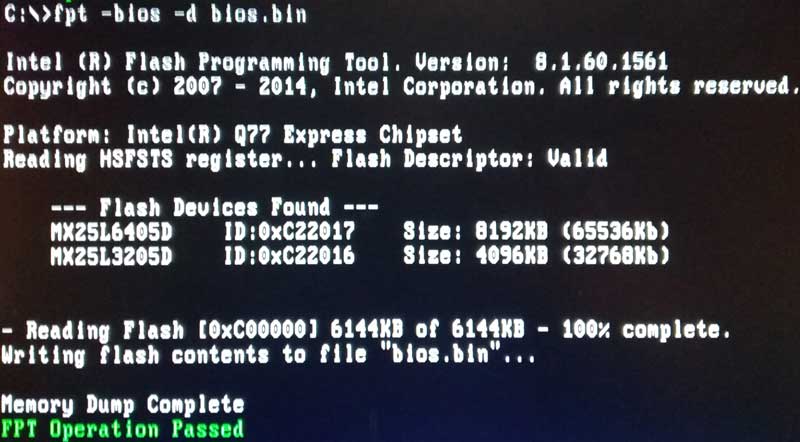
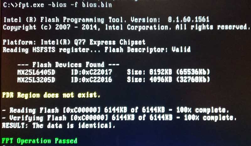
The dump gave this output…

C:\7010\ME System Tools Version 8\Intel ME System Tools v8 r3\Flash Programming Tool\Windows>FPTw -bios -d dump.bin

Intel (R) Flash Programming Tool. Version: 8.1.60.1561
Copyright (c) 2007 - 2014, Intel Corporation. All rights reserved.

Platform: Intel(R) Q77 Express Chipset
Reading HSFSTS register… Flash Descriptor: Valid

— Flash Devices Found —
MX25L6405D ID:0xC22017 Size: 8192KB (65536Kb)
MX25L3205D ID:0xC22016 Size: 4096KB (32768Kb)


- Reading Flash [0xC00000] 6144KB of 6144KB - 100% complete.
Writing flash contents to file “dump.bin”…

Memory Dump Complete
FPT Operation Passed

---------
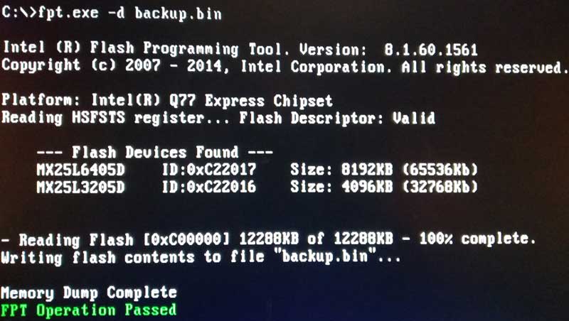
I noticed there are two chips of different sizes a 8 MB and 4 MB. As the dump is 6144KB and this size doesn’t match the MX25L6405D 8MB chips contents size (65536Kb). Is the dump.bin made up of parts of both the 8MB and 4MB chips or just part of the 8MB chip?

As the ‘FPT Operation passed’ I felt it was safe to try to flash the dump.bin back to the bios

Then the attempted flash gave this output…

C:\7010\ME System Tools Version 8\Intel ME System Tools v8 r3\Flash Programming Tool\Windows>FPTw -bios -f dump.bin

Intel (R) Flash Programming Tool. Version: 8.1.60.1561
Copyright (c) 2007 - 2014, Intel Corporation. All rights reserved.

Platform: Intel(R) Q77 Express Chipset
Reading HSFSTS register… Flash Descriptor: Valid

— Flash Devices Found —
MX25L6405D ID:0xC22017 Size: 8192KB (65536Kb)
MX25L3205D ID:0xC22016 Size: 4096KB (32768Kb)


Error 280: Failed to disable write protection for the BIOS space!


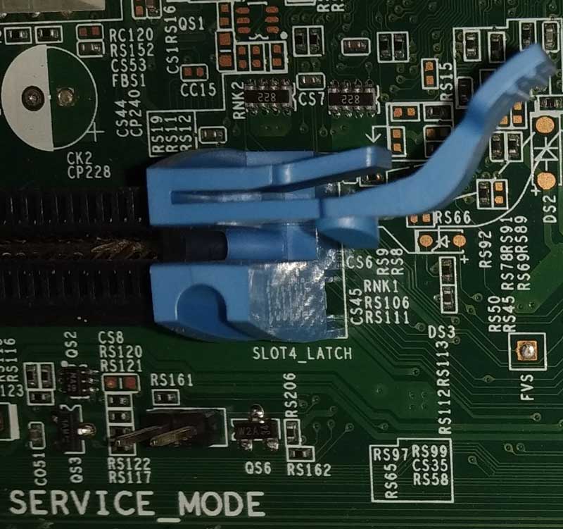
I am assuming I can disable the lock to allow bios flashing but don’t know how. Is there a jumper setting on the motherboard or another tool in the ME system tool download. If I can flash the copy of the bios I just made (dump.bin) then I have confidence that I could flash a modded version.

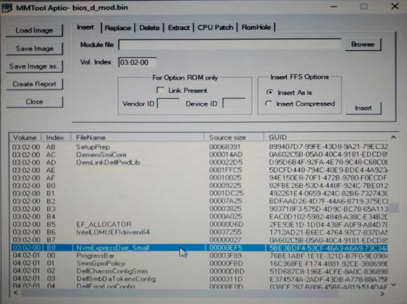
The reason I would like to mod the bios is to get a NVME drive working through the graphics PCIe slot and allow this to be bootable. I managed to do this on an AMD motherboard (https://www.asus.com/uk/Motherboards/AM1MA/) using a guide on this forum but the AM1 CPU is a bottleneck on the performance of that system.

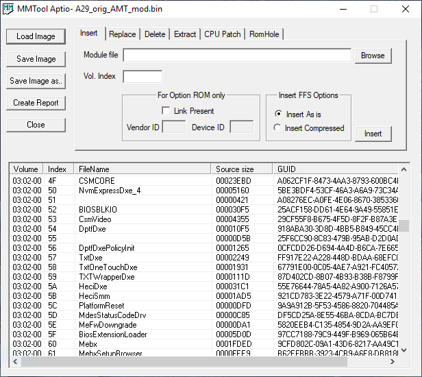
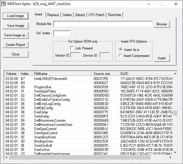
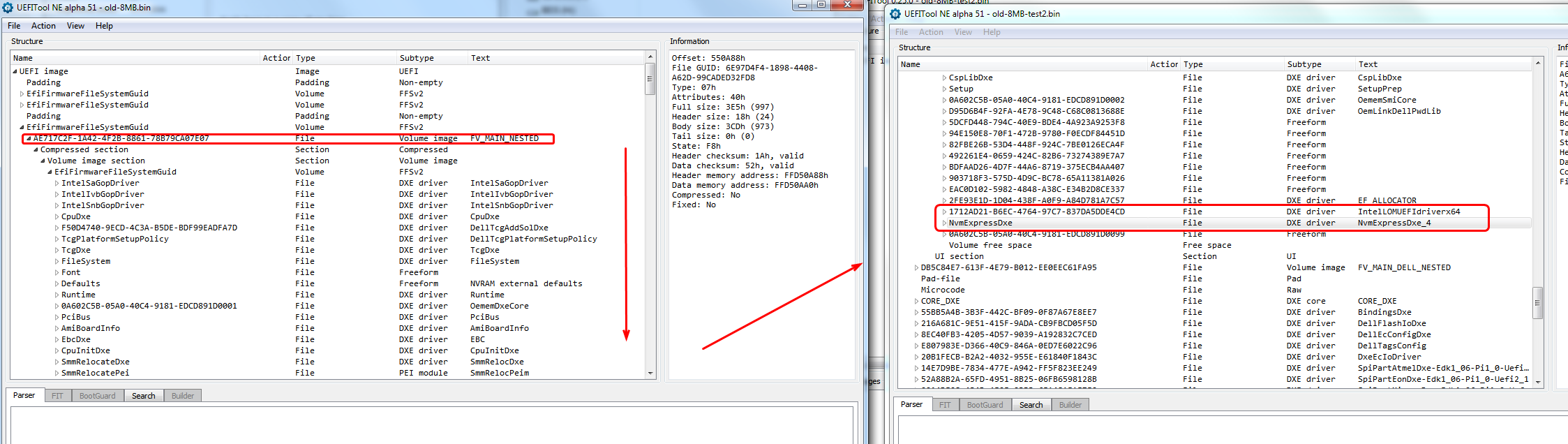
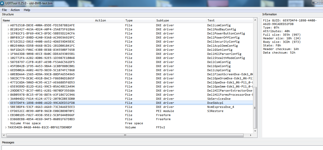
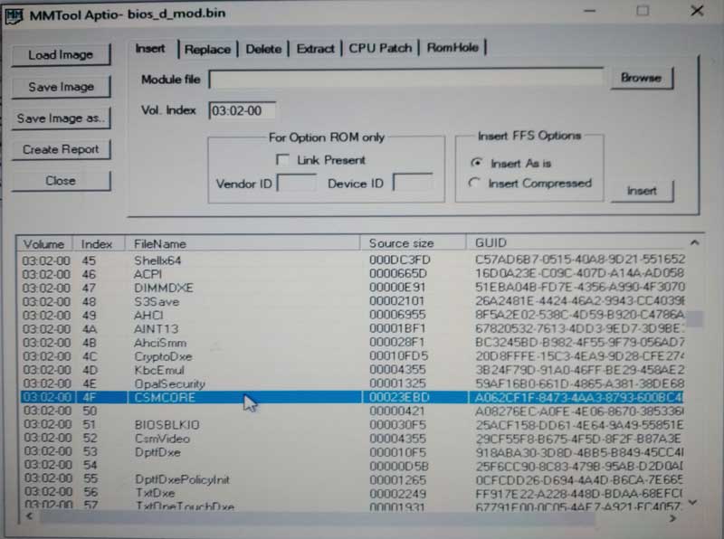
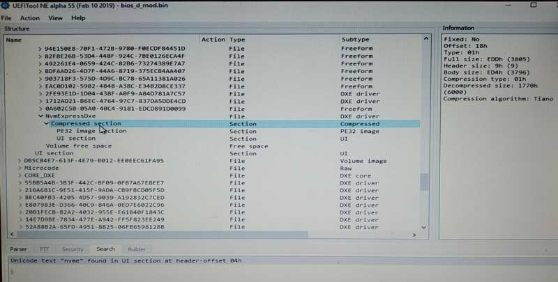
The Optiplex 7010 has UEFI bios and now I have the dump.bin I assume there is a tool to load the bin file and then I can insert the NVME functionality like in the AMI bios guide.

Then I assume the final step is to unlock the bios to allow it to be flashed but it would be very helpful to clarify which tool to open the bin file, which NVME module to insert for this Dell 7010 and how to get around the bios lock to flash the modified file.

@sith - Dump entire BIOS via >> FPTw.exe -d bios.bin
Or use universal BIOS backup toolkit. And yes, BIOS/ME/etc is split between the two chips and not in a even/sensible way.

To disable that lock requires a modified BIOS, programmed in, then the lock would be gone. To get around that without this process you need to use AFU based flasher not FPT, and the AFU version needs to be one that allows mod BIOS (The stock included one may allow that, unsure).
Or, if the board has a FD/FDO/ME/Service 2pin jumper on this would disable the FD locks and this lock too I think, and allow you to read/write all BIOS regions as a whole. Check the board over.

You can pinmod the board and unlock the FD, see E1 method here - [Guide] Unlock Intel Flash Descriptor Read/Write Access Permissions for SPI Servicing
Once this is done, you dump entire BIOS, edit the FD to unlock everything, then reflash (without rebooting, otherwise you have to pinmod again). Editing the FD itself to unlock is shown in second spoiler in section “B” at top
This may or may not remove the 280 error, you’d have to try and see, if same error or new etc. If same, then send me the dump and I will modify it, but that would need programmed in or flashed in some other non-FPT way.

And yes, you can flash mod BIOS, I was helping someone with that not long ago, for logo mods, I bet we’ve covered flashing mod in that thread let me find it.
No luck, he’s waiting on programmer due to no jumper on board - Dell Optiplex 50xx/70xx/90xx custom splash screen (2)
There’s also this method, see end of guide - [GUIDE] Modifying/Flashing Dell Bios using PhoenixTool (Updating to new RST ROM)

NVME Module can be inserted per this guide - [Guide] How to get full NVMe support for all Systems with an AMI UEFI BIOS

Test dumping the BIOS from DOS using the included AFUDOS >> AFUDOS.exe backup.bin /O
Then test flashing it back >> AFUDOS.exe backup.bin /P /B
Also test with flash2.exe >> Flash2.exe backup.bin /rsmb

I think this will work, both ^^, I’ve seen several threads now while looking around, users flashed mod BIOS using stock Lenovo tools, so may work OK


That stopped working at least 10 years ago, before the FD.

I found the “[Guide] Unlock Intel Flash Descriptor Read/Write Access Permissions for SPI Servicing” really helpful. Thank You.

I did search the motherboard carefully and near the 4x PCIe slot there was a 2 pin jumper which the manual (https://downloads.dell.com/manuals/all-p…nual4_en-us.pdf) on page 59 mentioned.

I connected the two pins and turned the PC on. I was informed I was in ‘Service mode’ and was presented with three options were presented. F1 key initially didn’t allow windows to load (Blue Screen). I restarted and ran the diagnostics option (F3?) still in service mode and passed all tests and then looked around (F2?) bios options changing nothing and the fourth restart F1 then worked and loaded Windows 10.

--------

I ran MEInfo and got an error, which I took as a positive sign (ME not working, but fans were not at 100%, didn’t notice if the sound was disabled)

C:\7010\ME System Tools Version 8\Intel ME System Tools v8 r3\MEInfo\Windows64>MEInfoWin64.exe -verbose

Intel(R) MEInfo Version: 8.1.56.1541
Copyright(C) 2005 - 2014, Intel Corporation. All rights reserved.


FW Status Register1: 0x1E040185
FW Status Register2: 0x12520106

CurrentState: Normal
ManufacturingMode: Disabled
FlashPartition: Valid
OperationalState: Bring Up
InitComplete: Initializing
BUPLoadState: Success
ErrorCode: No Error
ModeOfOperation: Unsecured mode by H/W jumper
ICC: Valid OEM data, ICC programmed
PhaseStatus: UNKNOWN


HECI device is found to be disabled.

Windows OS Version : 6.2.9200 “”
OS BIOS Support : Legacy

Table Type 218 ( 0x DA ) found, size of 251 (0x FB ) bytes
Table Type 218 ( 0x DA ) found, size of 71 (0x 47 ) bytes
Table Type 0 ( 0x 00 ) found, size of 24 (0x 18 ) bytes

Windows OS Version : 6.2.9200 “”
OS BIOS Support : Legacy

Table Type 218 ( 0x DA ) found, size of 251 (0x FB ) bytes
Table Type 218 ( 0x DA ) found, size of 71 (0x 47 ) bytes
Table Type 0 ( 0x 00 ) found, size of 24 (0x 18 ) bytes
Table Type 1 ( 0x 01 ) found, size of 27 (0x 1B ) bytes
Table Type 2 ( 0x 02 ) found, size of 15 (0x 0F ) bytes
Table Type 3 ( 0x 03 ) found, size of 22 (0x 16 ) bytes
Table Type 4 ( 0x 04 ) found, size of 42 (0x 2A ) bytes
Table Type 7 ( 0x 07 ) found, size of 19 (0x 13 ) bytes
Table Type 8 ( 0x 08 ) found, size of 9 (0x 09 ) bytes
Table Type 9 ( 0x 09 ) found, size of 17 (0x 11 ) bytes
Table Type 10 ( 0x 0A ) found, size of 8 (0x 08 ) bytes
Table Type 11 ( 0x 0B ) found, size of 5 (0x 05 ) bytes
Table Type 12 ( 0x 0C ) found, size of 5 (0x 05 ) bytes
Table Type 15 ( 0x 0F ) found, size of 35 (0x 23 ) bytes
Table Type 16 ( 0x 10 ) found, size of 23 (0x 17 ) bytes
Table Type 17 ( 0x 11 ) found, size of 34 (0x 22 ) bytes
Table Type 19 ( 0x 13 ) found, size of 31 (0x 1F ) bytes
Table Type 20 ( 0x 14 ) found, size of 19 (0x 13 ) bytes
Table Type 25 ( 0x 19 ) found, size of 9 (0x 09 ) bytes
Table Type 27 ( 0x 1B ) found, size of 15 (0x 0F ) bytes
Table Type 28 ( 0x 1C ) found, size of 22 (0x 16 ) bytes
Table Type 32 ( 0x 20 ) found, size of 20 (0x 14 ) bytes
Table Type 34 ( 0x 22 ) found, size of 11 (0x 0B ) bytes
Table Type 36 ( 0x 24 ) found, size of 16 (0x 10 ) bytes
Table Type 41 ( 0x 29 ) found, size of 11 (0x 0B ) bytes
Table Type 177 ( 0x B1 ) found, size of 12 (0x 0C ) bytes
Table Type 178 ( 0x B2 ) found, size of 76 (0x 4C ) bytes
Table Type 208 ( 0x D0 ) found, size of 16 (0x 10 ) bytes
Table Type 210 ( 0x D2 ) found, size of 12 (0x 0C ) bytes
Table Type 216 ( 0x D8 ) found, size of 9 (0x 09 ) bytes
Table Type 217 ( 0x D9 ) found, size of 8 (0x 08 ) bytes
Table Type 220 ( 0x DC ) found, size of 20 (0x 14 ) bytes
Table Type 221 ( 0x DD ) found, size of 19 (0x 13 ) bytes
Table Type 222 ( 0x DE ) found, size of 16 (0x 10 ) bytes
Table Type 255 ( 0x FF ) found, size of 8 (0x 08 ) bytes
Table Type 13 ( 0x 0D ) found, size of 22 (0x 16 ) bytes
Table Type 127 ( 0x 7F ) found, size of 4 (0x 04 ) bytes

Error 9458: Communication error between application and Intel(R) ME module (FW Update client)

Error 9459: Internal error (Could not determine FW features information)


So feeling positive I tried to do the download that shouldn’t have worked according to post #135 above.

I have seemed to have downloaded the entire contents of both the 4MB and 8MB chips.

C:\7010\ME System Tools Version 8\Intel ME System Tools v8 r3\Flash Programming Tool\Windows>FPTw -d bios.bin

Intel (R) Flash Programming Tool. Version: 8.1.60.1561
Copyright (c) 2007 - 2014, Intel Corporation. All rights reserved.

Platform: Intel(R) Q77 Express Chipset
Reading HSFSTS register… Flash Descriptor: Valid

— Flash Devices Found —
MX25L6405D ID:0xC22017 Size: 8192KB (65536Kb)
MX25L3205D ID:0xC22016 Size: 4096KB (32768Kb)


- Reading Flash [0xC00000] 12288KB of 12288KB - 100% complete.
Writing flash contents to file “bios.bin”…

Memory Dump Complete
FPT Operation Passed


I opened the bios bin in UEFITool and MMTool. I find UEIFTool easier to use but I searched for CSMCore after finding that DXE modules are in two different places. I am a little confused about the hierarchy of the bin file.

Are Volumes, containing files, which contain compressed regions which contain settings such as the ‘text’ CSMcore.

I believe some DXE files are in two different volumes but I don’t see which volume each one corresponded to. In MMTools I can tell which volume I’m in but I get confused about finding the insertion place.

I will reread the NVME guide tonight and not try to understand this when I’m tired.

I also noticed this section (Top right ‘Information’ section of the UEIFTool) when the bios.bin was loaded and I was examining the Descriptor region.

Fixed: Yes
Base: 0h
Address: FF400000h
Offset: 0h
ReservedVector:
FF FF FF FF FF FF FF FF
Full size: 1000h (4096)
GbE region offset: 1000h
ME region offset: 5000h
BIOS region offset: 600000h
Region access settings:
BIOS: 0Bh 0Ah ME: 0Dh 0Ch
GbE: 08h 08h
BIOS access table:
Read Write
Desc Yes No
BIOS Yes Yes
ME No No
GbE Yes Yes
PDR No No
Flash chips in VSCC table:
EF3015 (Winbond W25X16)
EF3016 (Winbond W25X32)
EF3017 (Winbond W25X64)
207115 (Micron M25PX16)
207116 (Micron M25PX32)
C22015 (Macronix MX25L16)
C22016 (Macronix MX25U16)
C22017 (Macronix MX25L64)
1F4602 (Atmel AT25DF161)
1F4701 (Atmel AT25DF321A)
1F4800 (Atmel AT25DF641)
1C3015 (EON EN25Q16)
1C3016 (EON EN25Q32)
1C3017 (EON EN25Q64)
20BA15 (Micron N25Q016)
20BA16 (Micron N25Q032)
20BA17 (Micron N25Q064)
EF4015 (Winbond W25Q16)
EF4016 (Winbond W25Q32)
EF4017 (Winbond W25Q64)
207117 (Micron M25PX64)
20BA17 (Micron N25Q064)


Which tells me I have read and write access to the BIOS in the "BIOS access table:"

Does this just mean if I insert the NVME code in the correct place I can flash it with FPT while in service mode and it’s complete? I read in post #134 you felt I would need a different flash program than the FPT. I will try to find the other programs to try but tonight I will read more of the guides you have shared with me in your previous post.

I feel I’m making progress, Thanks to the Forum for getting me this far.

@Lost_N_BIOS I might have cracked this nut!

On the Motherboard, I found the Service Mode Jumper at the board’s edge near PCI slot 4.

Optiplex-7010-MT-Service-Mode-Jumper-Pins.jpg


Using Rufus I created a FreeDos bootable USB drive. I placed a version of AFUDOS and FPT onto the root of the USB drive. I had to put in the associated txt file for FPT to work.

I couldn’t get AFUDOS working but FPT I believe has worked. Could you please check the following few images and check I am interpreting the output correctly?

FPT-dumplock.jpg


The FPT -dumplock command only shows regions of the SPI chips that are locked. Bios isn’t listed and therefore one can read and write to it?

FPT-Bios-Dump.jpg


FPT-Dump.jpg


I was able to read the bios region and the entire SPI (4MB + 8MB) chips.

FPT-Bios-flash.jpg


I tried to flash back the bios region. Did this actually write or just compare (verify) the file and the bios region?

Then with the copies of the bios files, I found the volume where ‘Csmcore’ is located = Volume Index 03:02-00

MMTool-CSMcore.jpg


I was not able to insert the normal size NVME .ffs file. I didn’t have room to even install the small NVME .ffs file without compressing it while inserting it into volume 03:02-00

I saved the file and inspected it had inserted at the correct place.

MMTool-NVME.jpg


The small NVME file needed ~ 6000 B uncompressed and I only have ~ 5600 B available.

I examined the modded bios file and other compressed regions of DXE files are shown to have ‘None’ as the Compression Algorithm while the NVME file I inserted has ‘Tiano’ as the algorithm. Will this cause a problem?

UEIFTool-Tiano.jpg


Would you be willing to look at the modified bios file and tell be if their are any obvious reasons I shouldn’t try to flash it?

Any luck @sith with yours? I think I fried my bios, please have someone look at it. I decided to go off the reservation and I’m paying for it. Anyone know which programmer I need for this board “optiplex 7010” to try and recover it?


snakeman

Hello @snakeman. I am still waiting on an NVME drive (Asgard 250GB ~ £30 from Aliexpress) to arrive. I also better order another NVME to PCIe adaptor. I don’t really want to take the Asgard I’ve got already out of my daughters PC, just to mess around with the Dell. I haven’t pulled the trigger yet. I hoped I’d have had some feedback from the forum to give me the faith, I was not about to mess it all up and do something stupid.

What did you do to mess things up? I am happy to look at a bin file you flashed in case there is anything obvious I see different to my 7010. I noticed on my windows bios dump there were sections that were all FFFF and this was less common on the dos FPT bios dump. I will likely only flash a modified dos dump of the entire chips (12 MB)

Sorry for late replies!

@sith - yes, that looks like you wrote BIOS region back correctly via FPT, it’s comparing file and current BIOS region contents after the write action completed
I mentioned you would need to disable BIOS Lock, or use some other program/method because I didn’t know then you had the service jumper (Other users with same board said they didn’t have jumper)
I can’t tell from your image if the NVME Mod was done correctly, and your mention of having size issues sounds odd to me (This is rare from what I’ve seen).
Upload your FPT dump for me and I will test mod it and let you know if you have correct position and if you need to use small or can use normal NVME file (I will not use MMTool, unless forced to by BIOS )

@Boroda944 - you need to get full dump from other threads here and replace your service tag, serial, MAC Etc, - you can’t use BIOS from EXE
There is 7010 dumps here, which I think you found - Optiplex 7010 and VPro/AMT/ME (10)

@snakeman - did you get it fixed? If not, you need CH341A programmer and SOIC8 test clip cable (If both BIOS 8 pin and soldered to board)

plutomaniac - what stopped working 10 years ago, entire BIOS dump via FPT, or Universal BIOS backup toolkit. You confused me good on that one
Why would FPT dump not work? And on the later, I use this often, have tested myself on modern boards and have users send me dumps from it too, so unsure which you meant?

I’m talking about Universal BIOS Backup or whatever it was called

@lost_n_bios yes I reflashed it with -rewrite before I rebooted with -greset.


@sith here is a copy of my bios
@sith and @LOST_N_BIOs The "mod" version includes nvme. Please check to see if its correct.
snakeman

A29_orig_AMT.zip (5.82 MB)

A29_orig_AMT_mod.zip (5.83 MB)

plutomaniac I thought maybe so, yes it still works fine, I use it often and suggest it for others and get dumps often too when necessary. There may be some BIOS it wont work on, but I’ve not seen any that I can remember.
This is the one - https://www.majorgeeks.com/files/details…up_toolkit.html

@snakeman - not sure what you want checked there between the two? I checked NVME mod and it’s not done correctly, but may still function (boot-wise and NVME-wise), anything else needing checked I need more info.
NVME Module should be inserted after GUID 1712AD21-B6EC-4764-97C7-837DA5DDE4CD, but also really unsure in this instance since the main volume is nested within another volume, normal position would be after GUID 6E97D4F4-1898-4408-A62D-99CADED32FD8 in that same main volume
If you want to put it in the same volume as CMSCore then put after GUID 1712AD21-B6EC-4764-97C7-837DA5DDE4CD - IntelLOMUEFIdriverx64

@Lost_N_BIOS Sorry for my late response.

I believe I may have nested DXE volumes also. I will attach the bin files I took from the dos environment. I am getting quite excited that I might just get this working.

I had to use WinRAR to get these less than 6MB and of a file type, I could upload.

BIOS_d.rar has the 6MB Bios dump from my Optiplex 7010 taken in a dos environment

bios_d_mod.rar has the compressed small NVME DXE module inserted into a nested DXE volume

BIOS_d.rar (3.23 MB)

bios_d_mod.rar (3.24 MB)

@sith Did you ever get your adapter? I "m waiting to hear your results. Let me know what type adapter you are using or going to use.


snakeman

Hello @snakeman

I am still waiting on the adaptor but the NVME arrived at my dad’s quite quickly. He will bring it over next time he visits me.

The NVME to PCIe adaptor I used on the ASUS AM1 and that I am going to use on the Dell Optiplex 7010 is this one costing £1.91 in the sale

https://www.aliexpress.com/item/New-arri…2977637883.html

The price of the Asgard drive has also gone down to £29.22 and at the moment has a $5 discount on it which is ok for a 250GB NVME. The selling point for me was the Graphene heat spreader. It looks good and

https://www.aliexpress.com/item/New-arri…2967598274.html

My product review is the benchmarking results on the ASUS AM1M-A on that item is dated 28th Feb 2019 and reads…

The system is an AMD 5150 APU on an ASUS AM1M-A Motherboard with a modded bios I created to allow this drive to be bootable. Given the graphics card slot on AM1M-A is not PCIe 3.0 I am very impressed with the performance which is way better than my Samsung Evo 850 SSD.

CrystalDiskMark 6.0.1

Sequential Read (Q= 32,T= 1) : 1678.756 MB/s
Sequential Write (Q= 32,T= 1) : 1067.416 MB/s
Random Read 4KiB (Q= 8,T= 8) : 223.486 MB/s [ 54562.0 IOPS]
Random Write 4KiB (Q= 8,T= 8) : 210.218 MB/s [ 51322.8 IOPS]
Random Read 4KiB (Q= 32,T= 1) : 68.442 MB/s [ 16709.5 IOPS]
Random Write 4KiB (Q= 32,T= 1) : 63.937 MB/s [ 15609.6 IOPS]
Random Read 4KiB (Q= 1,T= 1) : 35.217 MB/s [ 8597.9 IOPS]
Random Write 4KiB (Q= 1,T= 1) : 51.823 MB/s [ 12652.1 IOPS]

Test : 1024 MiB [C: 6.8% (15.7/232.3 GiB)] (x5) [Interval=5 sec]
Date : 2019/02/26 22:47:38
OS : Windows 10 Professional [10.0 Build 17763] (x64)


It’s not setting the world alight but I hope on the Optiplex 7010 it will be faster. This NVME drive uses system Ram as the cache I believe. I don’t know if that’s an issue with power cuts etc. i.e. no time for the file index being written back to the NVME chips.

Re: Your Uploaded Bios files

I looked at the A29 bin and modified bin files you uploaded. I saw you inserted the NVME (large) module immediately after the CSMCORE module. What software did you use to insert it at index point “50”. With UIEFTool I couldn’t insert it into the correct place index point “B8” by inserting it after “B7” and the original “B8” I believe was free space at the end of the volume.

Snakeman Mod.PNG


Alternative index location.PNG


I believe UIEFTool wouldn’t let me insert it as there was too little space in the ‘correct location’ volume.EDIT: I was using the wrong version of UIEFTool, one that doesn’t allow insertion So with MMTool and the small NVME file (with compression), I inserted it into the same volume as the CSMCore module and MMTool’s automatically put it at the end of the volume after the “B7 IntelLOMUEFIdriverx64”

I will try again later today myself and see what my results are.
I used UEFItool version 2.60. Which version are you using?
Thanks for the links. I will take look in a few minutes.

snakeman

Until recently I have never used these type of tools and wasn’t sure where to get them from. I think one might have been from a website called ‘mydigitallife’ or ‘tweektown’ or something like that. My version of UEFTool might be an incompatible version as it’s version ‘NE Alpha 55 (Feb 10 2019)’ has a very different version number than yours.

https://github.com/LongSoft/UEFITool/releases

UEFITool_NE_A55_win32.zip

and MMTools was called MMTool 4.50.0.23.zip

@snakeman I was shopping and came across the programmer and clip Lost_N_Bios mentioned. I will link below the ones I purchased. I went with the USB programmer with the black PCB as I found a really informative video that explained how it’s used. Pin orientation, software function (Getting it in English - by moving the English language file into a directory) etc.

TEST CLIP (For 8 PIN CHIP) and 2 Adaptors

https://www.aliexpress.com/item/Free-Shi…1844277735.html (middle option with “2 parts” adapters = £1.64)

USB PROGRAMMER (To work with above Test Clip)


https://www.aliexpress.com/item/CH341A-2…27424c4dvN9Lrg (£1.54)

https://www.youtube.com/watch?v=5NYe21nFSDI (Long video but it might save you time by watching it and avoiding some mistakes. He also links to the software you need in the description.)

Finally, my 7010 came without those blue caddy things and I found them here…

https://www.aliexpress.com/item/1pc-Hard…2949180523.html

@sith I’ve been trying to follow the advice of the guys on this forum, thats how I ended up with 2.60!
@sith watching the video now
I need one that allow you to flash without removing it from the board.

https://www.youtube.com/watch?v=2Y06x1f22B0

another good link
snakeman

Evening @Snakeman

The USB programmer can connect to the 8 pin test clip and then you can program the chip in situ. Assuming you don’t have any electrical components (chokes, capacitors or sockets) in the way as the test clip isn’t the smallest of things.

I will link another video which shows a laptop bios being reflashed in situ.

https://www.youtube.com/watch?v=vgbWtxv_hqM

@sith - 7010 BIOS is 12MB total, 4MB + 8MB - Unsure what your 6MB dump is, DOS FPT of BIOS region only? If you have programmer, use that instead, dump both BIOS, unless you are just more comfortable with FPT and BIOS region, that’s fine too
Just general statement there on the BIOS size/files, I’m sorry this thread is not specific to you and I tried to look back to see what’s going on and why you posted BIOS for me, but I can’t figure that out.
NVME insert does not go inside or near CMSCORE, that’s just given as example to select in MMTool to be sure you are selecting the correct volume # when you insert with MMTool.
As a generic example, here is image, I inserted NVME module (full size) into 7010 8MB BIOS Dump (Inserted at" FV Main Nested", after last DXE module - same volume as CMSCore then put after GUID 1712AD21-B6EC-4764-97C7-837DA5DDE4CD - IntelLOMUEFIdriverx64)

Dell-7010NVME.png


I have also test inserted at the other possible working location, at end of main BIOS volume, after DxeSbACPI and the full size module inserts there fine too, but I do believe above location is best method for this BIOS layout

Dell7010-NVME-OUtsideFVNested.png


I described this with GUID Details at post #143, as second method in my comments at that post. The main ideal method I also describe there, as shown in above image (inside FV Main Nested), this method in first image is the ideal and suggested insertion location IMO

All these inserted done with UEFITool 25, no reason particular for that version, it was just the one I had open then.