Hi!
So the story is. The laptop’s battery is dead, so I have tried to update BIOS from recovery mode. Extracted the .fd file from official BIOS updater with WinRaR, placed it on a FAT32 pendrive, and started the laptop with END key + plugging in power adapter to get in recovery mode. When the beeps finished, I have tried to turn it off with pressing power button, but it won’t react. So waited for about 15 minutes, still nothing, pulled out power cable. After that, the laptop didn’t do anything, can’t turn it on, can’t enter recovery, it’s fully dead, just there is power on USB ports. I have disassembled it, flashed downloaded dumps to the SPI chips, and tried to turn it on. Still nothing.
What I have missed, why it’s not working? Any help is really appreciated.
@UDPSendToFailed - When you programmed “downloaded dumps” where did those come from, and where they shared as confirmed working? With your programmer, did you make a backup and make sure it verified before you wrote anything to the chip? If yes, please attach.
With your programmer after you programmed dump to chip, did you verify and make sure it all wrote properly? What is the BIOS chip ID, and what software version are you using and what chip ID did you select?
As for your initial recovery attempt with the .FD file, is that Dell’s recommended method, or did you read this somewhere? If you read somewhere, please link me so I can see if that sounds proper.
.FD file is not a complete BIOS, well the complete BIOS is there but you have to extract it (6MB) from the .FD and that probably needs further split for programming.
There may be more than one BIOS chip, maybe even three, please check. One may contain ME or other info, and another has EC FW, which due to your recovery attempt and the main issue, these may be all messed up too.
Do not attempt to write anything to them yet, but if you find them please dump and verify then attach those files as well. This is why it’s best to make dumps from all before writing anything, if you have those please attach
Is this your exact system Inspiron 15R 5520
https://www.dell.com/support/home/in/en/…5r-5520/drivers
*Edit again
I have no verified, there is three chips. One contains 128KB EC FW, one contains NVRAM and secondary BIOS volume (right), and the other contains FD, ME, and main BIOS volume (Left)
Later tonight I will split an image for you and get files ready you can use with programmer.
@Lost_N_BIOS
Thanks a lot for your reply! ![]()
I have downloaded these dumps from a forum, I don’t know if I’m allowed to write it’s name or not. But uploaded the dumps here: http://rgho.st/6mGTtJLKG http://rgho.st/6SrfXVxKK
I did make backup, but the files were fully empty, so flashed the dumps. My programmer is a PC motherboard with LPT port and SPIPGM. I’m 100% sure it writes the flash chips correctly, it can detect them by ID, verified the flashed content twice, and recovered another laptop with this method some years ago.
The first recovery attempt was for updating BIOS, and read it here.
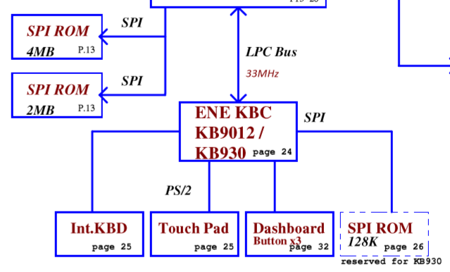
Checked the motherboard, and it’s datasheet, there are two SPI chips, and one 128KB flash embedded in EC. My laptop is an Inspiron 15R 5520 without AMD GPU.
So, I can only flash the two SPI chips on motherboard (EN25QH16 and W25Q32BV), but not the EC, it’s an ENE KB9012QF A3. Tried this method, but the PC won’t detect the internal flash.
Datasheets that I found: motherboard ec
You can name forums, we don’t censor anything here that I"m aware of, @UDPSendToFailed
Dumped empty files usually means you are not using the programmer with correct settings/options or it’s not compatible with the chips/system, thus will never be able to program/write correct either, until you solve the issue.
This can be incorrect connection at the BIOS chip/SPI Header, or into the programmer side, or it could be incompatible version of software used, or incorrect chip ID used. Sometimes exact ID is not one that works for certain chips/systems
Lets get a verified and valid dump from all chips now before we do anything, since you have wrote to them, now if you get empty dumps (even if verified) you will know there is some issue like mentioned above.
Can you dump the chips now, that you wrote to, and then compare those dumps in hex with the files you programmer to the chip. And open the dumped 2MB one in UEFITool, does it look similar to the file you wrote to the chip in this tool or hex?
What caused the original issue anyway, bad BIOS Update, or what?
Some other laptop years ago does not apply toward this one at all. All systems are different, all BIOS chips are different, so you can’t know for sure it’s working properly in this setup in the current configuration
Detect by ID does not automatically mean backup or write verifies files will be valid, which you found out already with your backup dumps being empty. I’ve seen 100% writes and reads end up being verified 100% FF’s or 00’s, both chips you dumped should not have been 100% empty
Or it may all be non-working currently due to the messed up EC which you can’t correct right now.
You may need to order a CH341A, which is suggested in the thread you linked. If the EC is messed up (128KB), which it may be if you know the dumps you tried already are valid, and you then re-dumped them after writing and then compared in hex (Was that a 100% match)?
I have a valid EC dump you can use, but you need compatible programmer first, go ahead and order CH341A on ebay now, they are only $2.50 but takes 3-5 weeks to arrive, or you can usually find on Amazon or Newegg type places too at a higher price for quicker shipping.
Here I created multiple BIOS bin files for you using A17 BIOS (5520A17.exe/QCL00A17.fd). The ones you linked are from A11 BIOS, they do have same Intel ME version though so that is good.
These are clean stock BIOS files, and never been loaded onto a board. I doubt anything will change though until you can fix the EC. The included EC is also extracted from the FD file, thus clean and proper
FD-Splice is the main BIOS image extracted from the FD file, before I cut it in three
http://s000.tinyupload.com/index.php?fil…167353542759540
The files are from BadCaps forum, but I don’t really know which, there are more dumps on the site.
Sadly the chips were really empty, not programmer’s fault. After flashing the dumps, and verifying, I have dumped them again, and compared in HxD. The flashed file and the dump from the chip were identical.
The original issue because of my bad ideas. The BIOS updater didn’t allowed me to update, because of the dead battery, nor with /forceit flag. So I did a really stupid step when tried to update from recovery mode. But I thought it can’t go wrong, because in the case of a real brick, this method used too to reflash. And yea, after removing the power, it died.
I will flash the files you sent today or tomorrow, hope it works. The only problem with EC reflashing is, I have tried the same method as in linked guide, just with rayer_spi programmer in flashrom. Tested with SPIPGM too, the EC’s flash showed like there is nothing connected, but it was. I think the keyboard connector is not in direct link with EC’s pins. So, if the laptop still not working after flashing 2 and 4MB chips, I will try to attach wires directly on EC’s pins. That would be hard because of really small size, but may work.
I don’t know if power on USB ports means something or not. Before when the laptop was working, only one USB had power, which marked as dedicated PowerShare port. Others were off, but now they are alive. Can this indicate something?
Anyway, thanks a lot for files, will report back if they worked or not. ![]()
OK, well those look like good files, as long as where you saw them posted they said working and not “Please fix these” But, they are old versions and probably pulled from working board if good, meaning would contain some other system serial, UUID, LAN MAC etc.
That is strange they were really empty, but at least now you have verified your writing to the chips are OK and properly writing.
Thanks for the info how this happened, I think there is some other flag too for battery issue you mentioned, but I’d have to dig around to find it (Or maybe that is the one you’re supposed to use)
When you did that, were you using official stock only EXE updater?
Best bet for the EC would be to purchase CH341A as the guide mentioned, they are super cheap ($2.50 on ebay + $2.60 for SOIC8 test clip cable), only downside is long 3-5 week wait for delivery. But, you may be able to find seller, or ask a bunch of sellers if any will ship using faster two week method.
Not sure on the USB questions, but it may mean you are closer to getting things going again! Good luck, hope the files I sent you work and you don’t have to mess with EC!
I have flashed the files, and verified them multiple times, sadly it’s not working. Same problem as before. I will try to reflash the EC directly, not through keyboard connector, if that will fail too, time to get a programmer for it.
To answer your question, yes, I used the official updater downloaded from Dell’s site. This is why it’s unclear for me, how it bricked the laptop.
Sometimes even stock BIOS update kills motherboards, it happens more often than we’d like, that is why often you see suggested to only update BIOS if necessary to fix a problem or if/when you do to only flash from DOS Etc.
Hope you can get that EC flashed, if not then yes you may need to pickup a CH341A. Where is the EC chip in the images in that guide, does it look like regular BIOS chips? If yes, then you need SOIC8 test clip cable if you do not have already.
Yea, that’s the problem… The EC’s flash is not SOIC8 like the other 2 flash chips. It’s embedded in the EC itself, not a separate chip on the motherboard. This is why I tried the keyboard connector method, in theory it enables the EC’s flash access to it’s internal SPI with some debug interface. 
I don’t know if CH341A can do more than I did with keyboard connector, because I can connect it only there, or somehow to EC’s pins directly. Or, maybe the EDI debug interface didn’t enabled itself when I tried earlier. I had connected pin 42 to ground to bring it in low state. Is there any way to check if EC is in debug mode or not?
Edit: Something I don’t understand. The datasheet says external flash, but there are videos on YouTube and guides on other forums where they modify the EC’s internal flash with this method…
And, maybe pin 41 should be connected to ground too?
EC FW is contained within a chip, but just not a SOIC type like the others. No problem, yes you’ll have to do the keyboard ribbon cable method.
That guide suggest CH341A as best way to do it, making me believe he had already tried other methods one shown on the guide, and found the best compatible one to use was the CH341A.
Like you mentioned, your method does not even detect the chip, so it can never work, unless you have some cable wrong or not securely connected etc.
I do not know how to check if it’s in debug mode or not. Best to follow that guide, and what was immediately apparent to me was he said best tool to use and what he used to write the remainder of the guide was CH341A, so I would get that before doing anything possibly destructive.
I will read about the internal / external flash thing, because the datasheet is confusing about that, and then give it a try with CH341A. Thanks a lot again for your help, will report back when I found something, or succeeded to access the EC’s flash.
You’re welcome! I agree it’s confusing, and best to use that guide you found, since he did seem to understand it all. Did you double check your connections with the current setup you have, and then all the guide mentioned?
Does the board need plugged in while doing this (Semi-powered, but not powered-on), if yes did you do that?
However, that image you posted above, shows SPI Flash (EC Chip) And it says use keyboard method “So you don’t have to take machine fully apart”
That leads me to believe on one side of the motherboard or the other you will find the EC SPI BIOS Chip (Probably looks the same as BIOS chips SOIC8, possibly 150mm instead of 200mm)
Just a guess, based on reading that image above again.
The motherboard was powered from it’s own adapter while I did it.
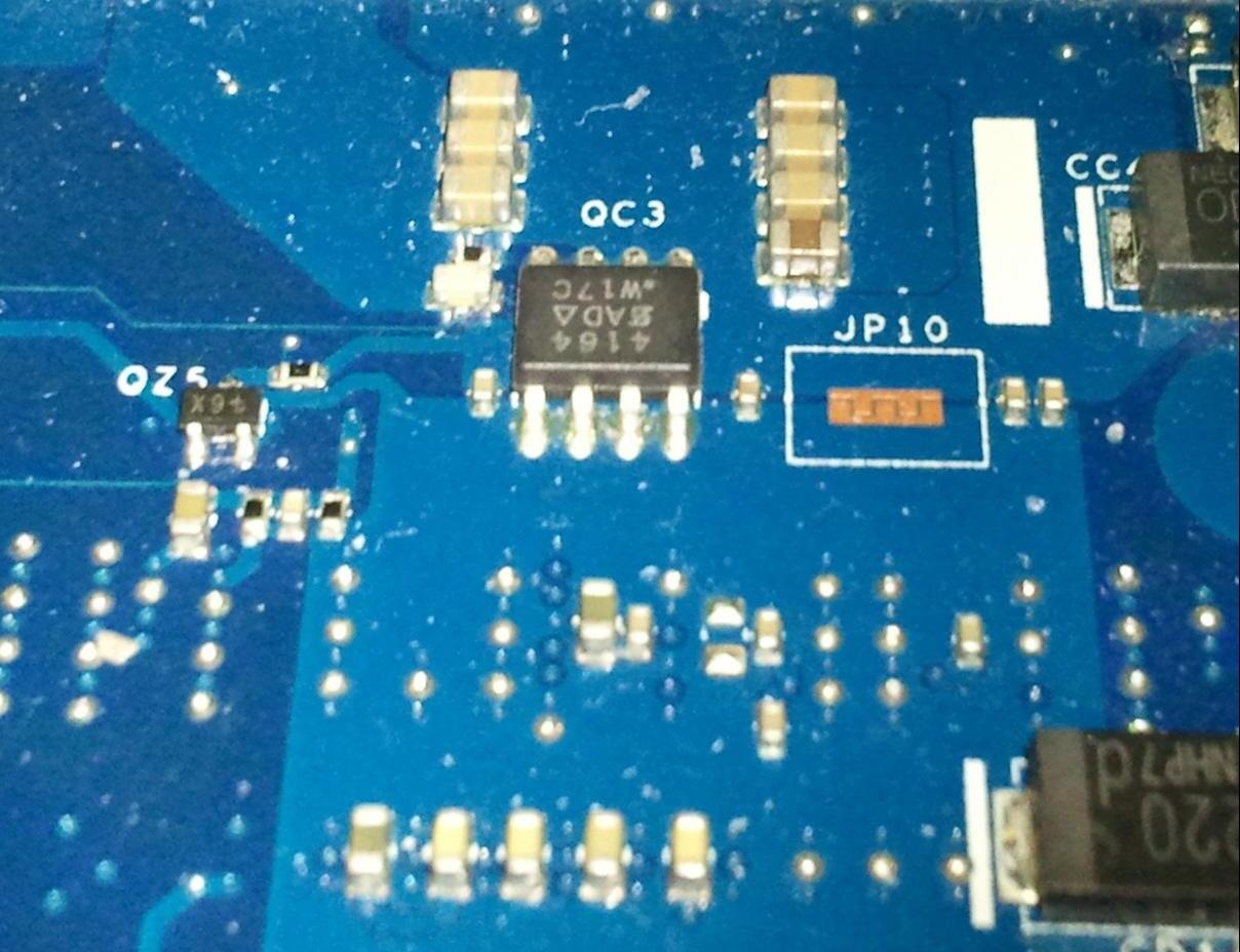
Here are some pictures of mb and datasheet:
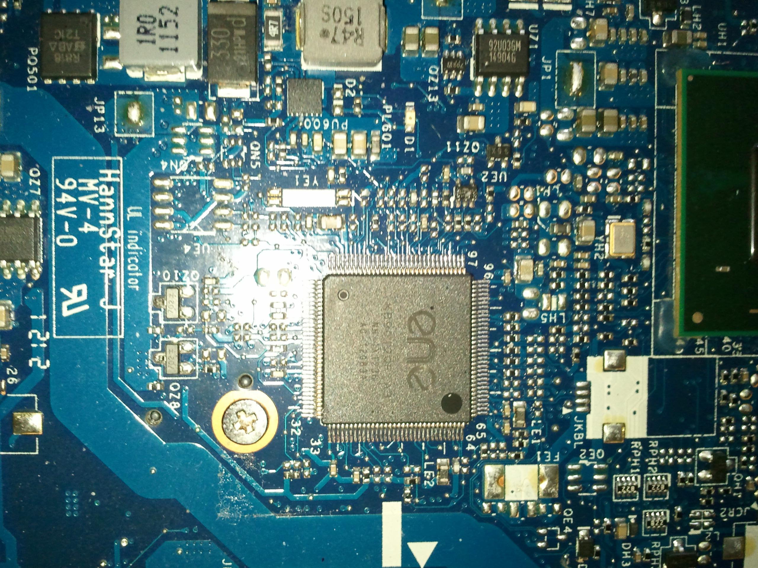
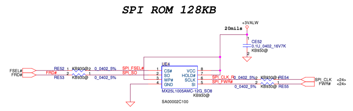
So the flash chip should be at UE4, for ENE KB930.
But no problem. I have found this in KB9012’s datasheet:
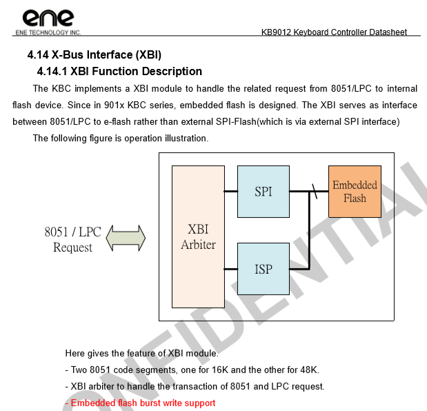
If my understanding was good, the XBI part of it is redirecting SPI related commands to external chip, for “non-E-Flash KBC”, so KB930. And maybe redirecting to internal flash chip for KB9012.
One thing that maybe caused the chip wasn’t detected. I just grounded pin 42 (TP_PLL_Lock), as in the guide, but not pin 41 (TP_TMUX), which is in datasheet where it says “Please note while TP_TMUX and TP_PLL_Lock keep low at the same time, a mechanism called FlashDirectAccess will enable”.
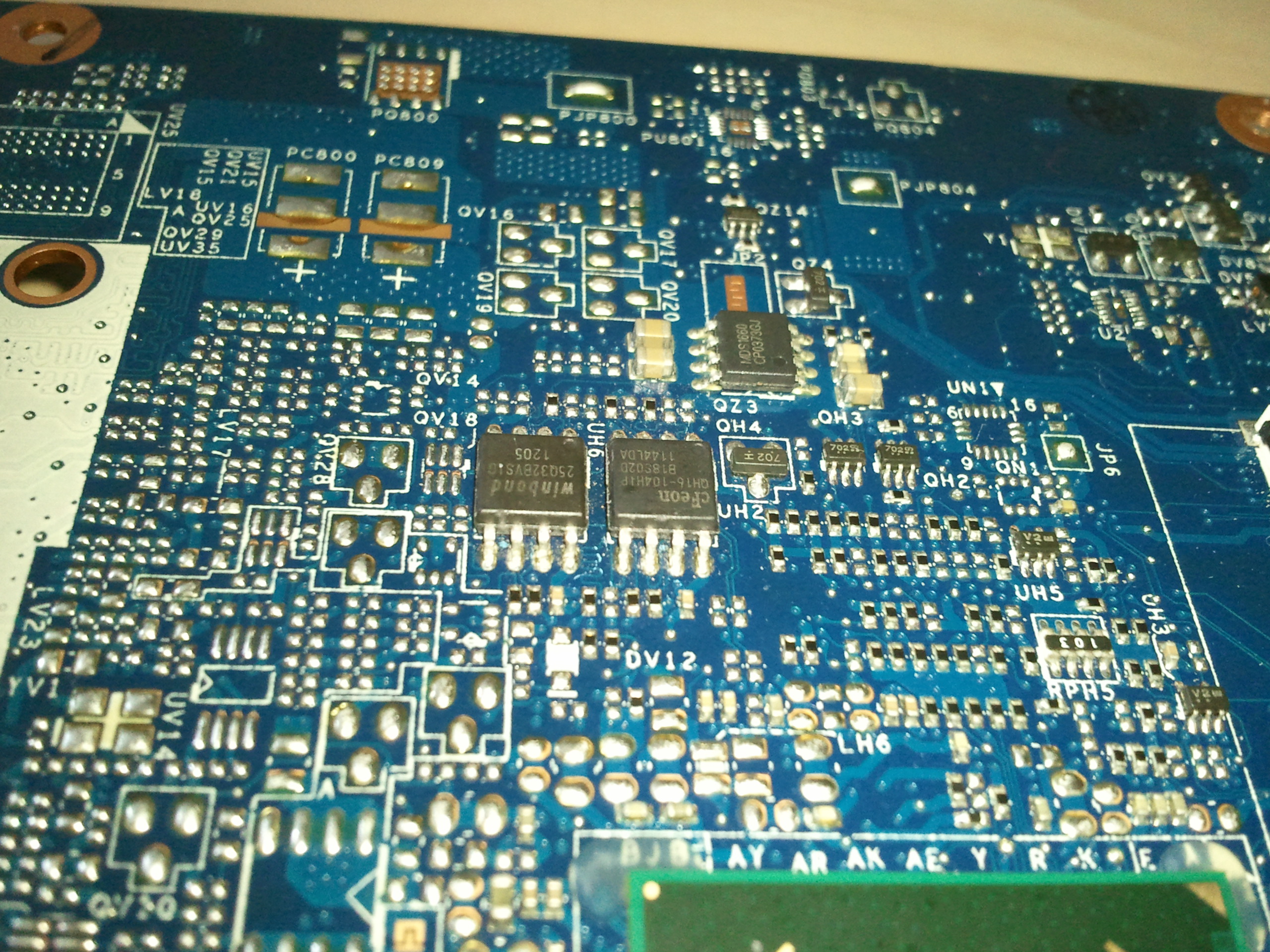
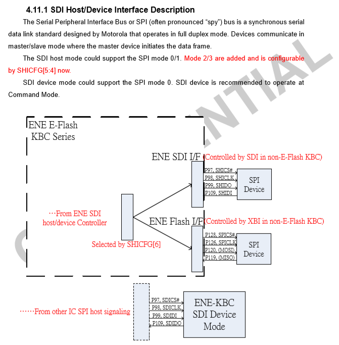
ENE KKBC is the keyboard controller, this is what allows you to flash through to the SPI. The SPI Rom 128KB image is of a SOIC BIOS chip as I mentioned.
There’s no no chip at UE4, did you dump all three SOIC8 chips and see what’s what? Looks like third one there under ENE chip, under 940 label, right at O or Q27
Yes, maybe you need to ground both of those for the lock to enable?
I googled for all SOIC8 chips on the motherboard, they are MOSFETs or voltage regulators except W25Q32BV and EN25QH16.
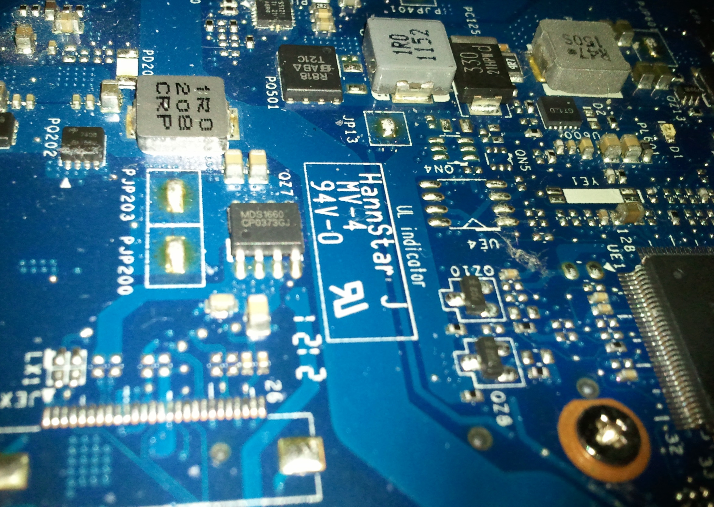
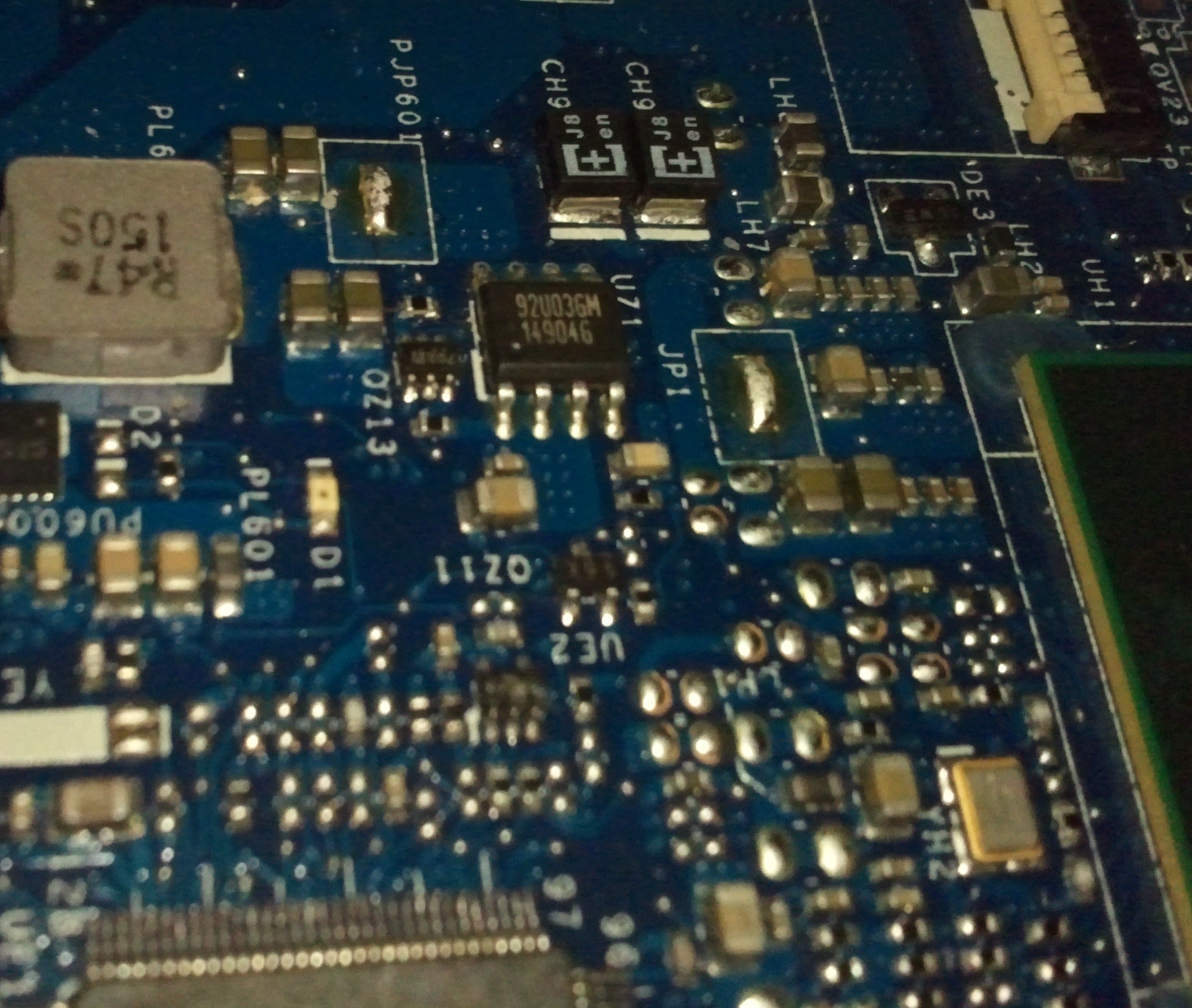
Thanks, yes you are correct, now that I can see it, that one I mentioned is not a BIOS/SPI chip!
Send me dump from both BIOS chips you showed in image two on post #13, maybe EC is stored within one of those in a BIOS region. This is common with Dell/HP, one chip is part or all of BIOS, and other is part of BIOS (or not) + EC, FD, ME
Label them in a manner so that you know which is which, in case I find EC and can update one of them for you to program back. *Edit, wait, I guess this wont help right now, since they were blanked and re-written by you already, so we have no way to confirm if EC was originally in one of them or not.
So never mind that thought  And, anyway, looking through all the dumps I have, none of them have EC contained within those two chips anyway, always a separate file and same as in the stock exe image EC was separate from the other two images, shouldn’t be typing and sleeping I suppose
I will do it somehow, just need to reach the EC’s internal flash through the debug mode. Maybe with pin 41, maybe with connecting SPI first and then laptop’s adapter, or with CH341A… I google more about that, hope someone had similar problem.
Maybe you just need to ground both those connections you mentioned instead of one, then your original method attempt will work.
Hi @Lost_N_BIOS !
Today I have flashed the files you sent, the laptop is working without problems. Thanks a lot! ![]()
@UDPSendToFailed - thanks for update. Do you mean files from post #4? If yes, thanks for confirmation all is working OK. Did you end up having to use the EC file too