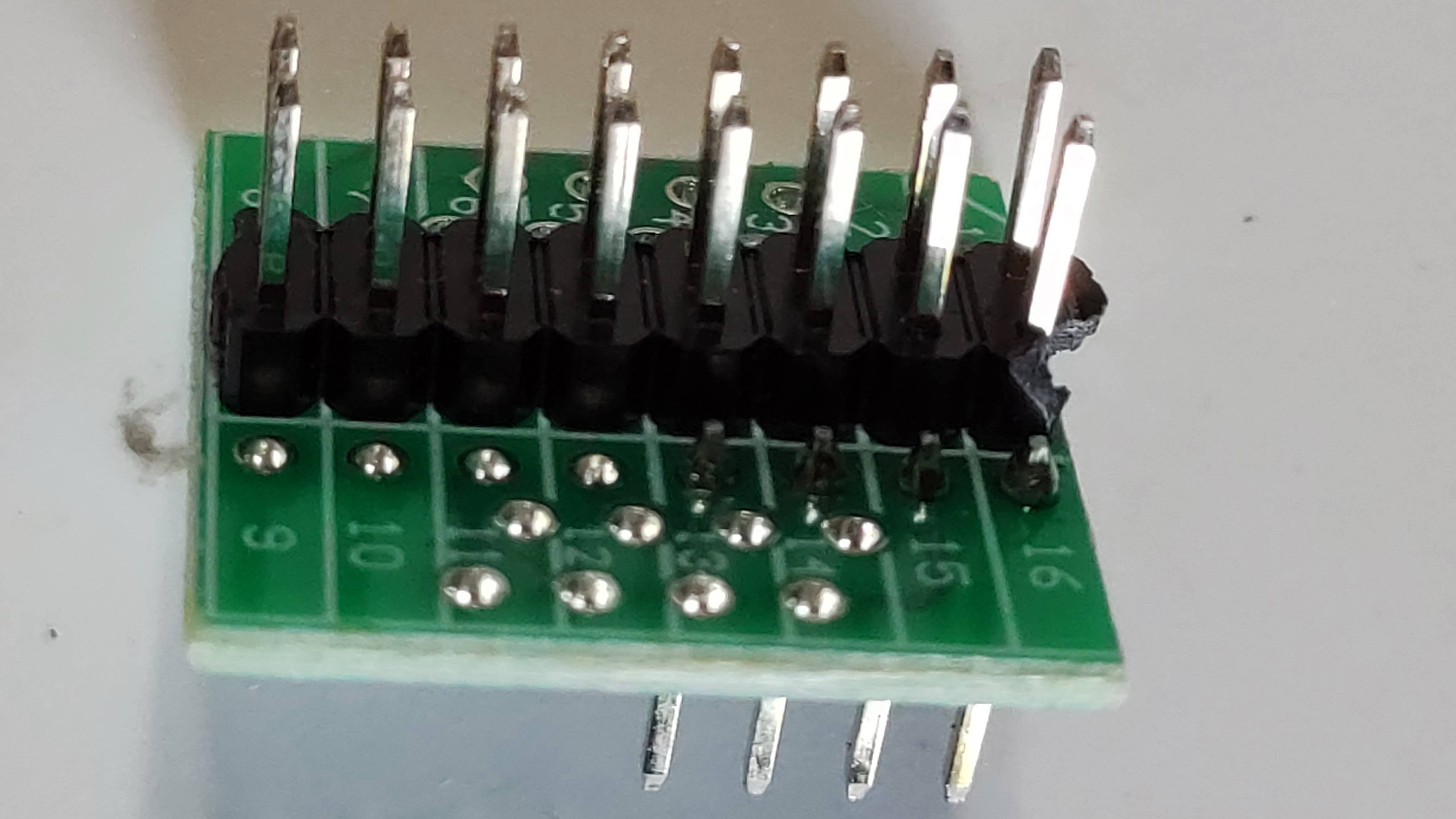
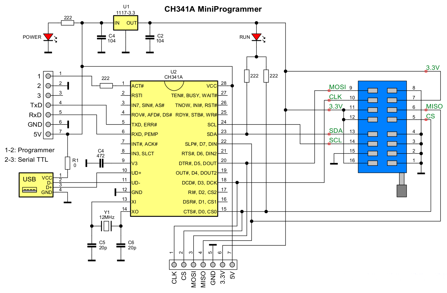
It all depends on the signals/wires assigned from the clip to the header and to the CH341 itself, any complains ask the chinese… now thats a full 16/16pin header, you need the check the Winbond W25Q256JV diagram of the SPI as usually the 8 midlle pins are not used.
I have 8 to 16 header and Dupont jumper wires…not a full header block that you cant exchange pin/wire assignment… you may have to modify the something in clip (The needles) itself (You cant on the header) but you can also break the solder on the wires doing so…cheap stuff
To understand a bit of all this “garbage” lol, take a look at this user issue/thread
Bricked Dell Optiplex 5060 + CH341a + SOP16 > Alive again - BIOS/UEFI Modding / Reports: BIOS Modding Results - Win-Raid Forum (level1techs.com)
It needs a lot of dedication…over_n_out, Good luck