Hi all,
Just signed up for these forums! I wanted to ask the pros here before I potentially messed something up.
My motherboard (Gigabyte X570 AORUS ELITE WIFI) has a default RGB color of Orange during boot up and wake from sleep. I dislike running Gigabyte’s RGBFusion software just to change the color to static white.
I found a blog post (bitservices.io/blog/gigabyte-rgb-hidden-bios-settings) from someone else with this issue, they used a modified GRUB (github.com/datasone/grub-mod-setup_var) to change the hidden BIOS values that control the RGB mode/Blue/Green/Red values.
These default RGB values are stored together in a string of values “03 00 21 FF” The 03 is the RGB mode (static) and the 00 21 FF are the Blue/Green/Red values from 00 to FF to create the default orange color on boot.
Unfortunately the linked blog only details out the GRUB offset locations for his particular motherboard and BIOS version.
So, could I do the following?
1. Download the latest BIOS for my motherboard
2. Open in hex editor, search for the string “03 00 21 FF” (I did this and found the string in a single location in the BIOS so I’m pretty sure that’s it)
3. Change the blue/green/red values to get static white "03 FF FF FF"
4. Save modified BIOS and flash with one of the modified EfiFlash tools (v0.87) that’s on this forum
Anyone see any issues with this or a better way to do it?
Thank you!
@thatdude333 - I can make you BIOS with access to RGB setting revealed within the hidden bug/backdoor settings area if you want?
Otherwise, yes, you can edit BIOS to change the default how you mention, but you will need to also do this edit first (post #79) before you can Qflash the mod BIOS in (last instance, look below that for the byte to edit)
On BIOS 31q, the byte to edit is at FE4E27h. Or yes, you can use mod EFIFlash if you wanted 
If you use mod BIOS the way I mentioned, with RGB setting visible to you via backdoor access method, you wont have to redo the edits if CMOS gets cleared, you can just change directly in BIOS.
Or, I can make you BIOS with the defaults all changed to white, so it’s always that way no matter what.
But yes, what you outlined will change the current applied default. But, I’m not sure if that will remain same though, after you flash it in and then load optimized defaults.
Due to what you see at 37370 is only the “current/live” NVRAM default, editing that without changing other stored defaults (that you’re not seeing via direct hex searching).
The area you’re editing may get changed once you flash BIOS and load optimized, I am not sure, you’d have to test to see outcome.
If you change it how the guide shows, using setup_var3, that will be after you’ve already loaded optimized defaults and would then be changing the current/live applied value.
If you want mod BIOS with RGB revealed in the bug/backdoor area and for me to show you how to access that, let me know 
Also, if you do want this, let me know what BIOS version.
@Lost_N_BIOS - Thank you so much for such a detailed and knowledgeable reply!!
I would love a modded BIOS with RGB settings revealed, that seems like a more reliable way to do this versus hex editing, and as you said, that might not even work after loading optimized defaults.
The BIOS I am using is F31q (latest) for the Gigabyte X570 AORUS ELITE WIFI. Here is the direct link from Gigabyte’s website → download.gigabyte.com/FileList/BIOS/mb_bios_x570-aorus-elite-wifi_f31q.zip
Would you also be able to share or point me to a guide on how you do this? I would love to learn.
Thank you again!!
@thatdude333 - You’re welcome, and thank you!! 
At >> Settings >> Misc page, can you already see >> LEDs in Sleep, Hibernation, and Soft Off States?
Or, do you only see >> LEDs in System Power On State
Yes, I agree, modded BIOS for this would be best, if you’re not going to use setup_var to change the setting after you’ve already got BIOS setup the way you want (plus that’s lost on reset too anyway, and you’d have to do all over again)
Yes, I will make you a detailed outline on how to do this edit, it’s only 4 bytes to change (plus one more if you need the above setting I asked about made visible too)
thank you @thatdude for opening this thread. I am also very interested in this since RGB Fusion SW from gigabyte is a very unstable and shitty piece of software. ![]()
@Lost_N_Bios: as stated I am also very interested in a short tutorial on changing these values for an Gigabyte Aorus B550i AX Pro ITX Board. Thanks in advance for your support here.
What would you rate as the most safest way to modify the RGB values (I am a total newbie to BIOS modification/unhide BIOS settings) - GRUB ( does it also work for my board in the same matter?) or modified BIOS?!
Thank you!
@titusatwork - Hopefully you can follow along with the tutorial I’ll post for thatdude333 here shortly
Values and offsets for the edits I’ll show in the outlined steps will NOT be the same for your BIOS, but the edits in general will be the same, so all you’ll have to do is follow along but use your BIOS instead.
If you wanted to use grub/setup_var3 to change stuff like the guide he linked, you can do that also. Yes, it should work for your system too.
Modified BIOS is best, since if you use the setup_var method, it will be changed back any time you load optimized defaults.
With mod BIOS, the settings will always be there for you to directly change in the BIOS, so you could change there any time instead of having to use setup_var each time you want to change
@Lost_N_Bios - Under Settings >> Misc in my BIOS, I have both settings:
- LEDs in System Power On State
- LEDs in Sleep, Hibernation, and Soft Off States
thank you again for your help!
@thatdude333 - You’re welcome! OK, then thanks for letting me know This will make your edit one step/module modification shorter than I planned.
Guide will be posted shortly, once I make a Mod BIOS for you and put package together
----------------------------------------
RGB Setting Reveal Edit -
@thatdude333 @titusatwork
Tools Required >>
UEFITool - https://github.com/LongSoft/UEFITool (Downloads in “releases” area, near top right side you will find link
I use NE Alpha 51.0 for inspection, extractions etc - this saves correct name automatically, and you can right click on any module and view via hex as-is or body
For insert/replace, you need to use regular version 25-28, I suggest 25.0 as it tends to cause the least problems with certain possible issues.
You can also use regular version for extraction if you want, but you have to name the file yourself that way.
51 NE Alpha - https://github.com/LongSoft/UEFITool/releases/tag/A51 (Win32 if using Windows)
25.0 - https://github.com/LongSoft/UEFITool/releases/tag/0.25.0 (Same as above )
Universal IFR extractor - I use donovan6000’s 0.7 version most often, it gives more info but does not work on some BIOS fully (ie Insyde), but either will work fine for this edit
https://github.com/donovan6000/Universal-IFR-Extractor (donovan6000’s page, but only 0.5 is linked here)
https://github.com/LongSoft/Universal-IFR-Extractor (Longsoft version 0.3.7 here, but only 0.3.6 has windows version, included in below package)
Package I uploaded w/ 0.7 + 0.3.6
http://s000.tinyupload.com/index.php?fil…806383987040253
thatdude333 - Also, here is a pre-modified BIOS, along with my extracted before/after files.
This way you can also look at/compare my edited files vs stock, in case anything is confusing below or you are not 100% sure
http://s000.tinyupload.com/index.php?fil…925441035268550
titusatwork - Do you need me to make you example package w/ mod BIOS too, or do you want to try going at it with the guide alone?
-------------------
Let’s do this edit >>
Info is below the “Change Log” area, you will use bug/backdoor method #2 to gain access to RGB that will be revealed after this edit.
[OFFER] Gigabyte Z390 M Gaming UPD + Completely Revised Blue Theme
RGB Setting will be >> @ Sys Info >> Peripherals >> RGB Fusion
Direct Key-In Hex Value - Don’t Press Enter Before Keying In Value, Or At All, It’s Not Necessary and may/will freeze BIOS
First - Disable Qflash Mod BIOS Block
1. Open BIOS file as a whole in hex editor
2. Search “BDR” and go to last one found (@ FE4DC5h)
3. About 6 lines below that, at FE4E24h you will find 50 01 04 01 << Change the last 01 to 00
4. Save file as modfilename.31q (you pick name, just make sure it’s not same as original, unless you work in another folder, only extension needs to remain same)
Here in post #79 is a general example and info about this edit
Second - Do RGB reveal Edit
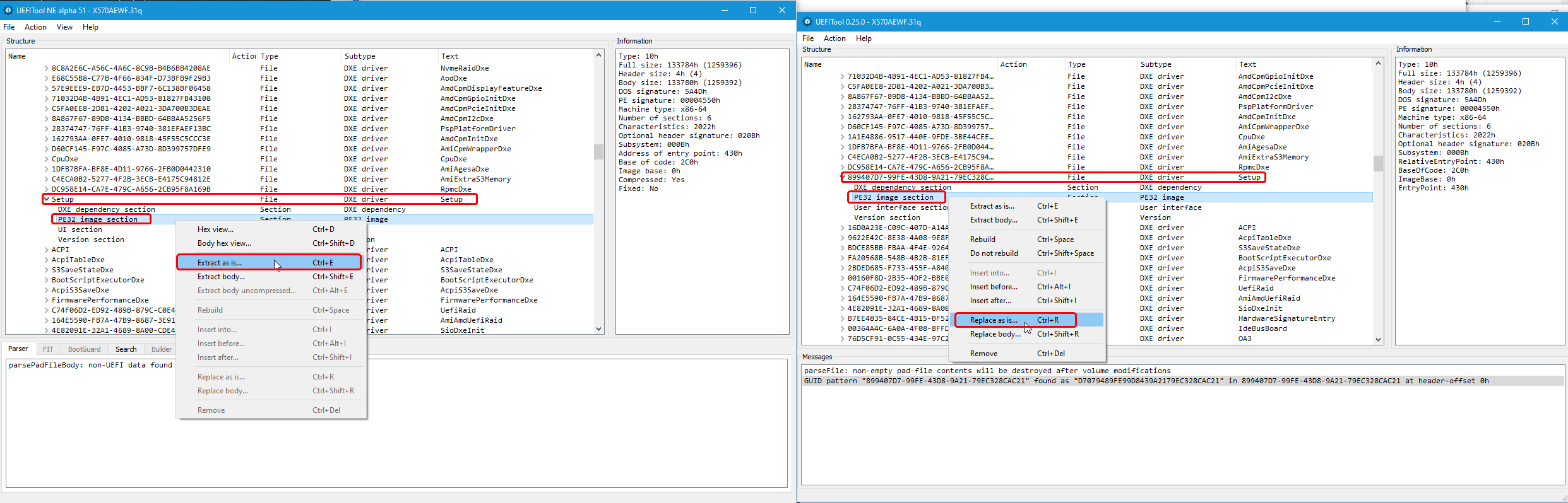
1. Open modified BIOS from above edit in UEFITool 51.0
2. Search via GUID >> 899407D7-99FE-43D8-9A21-79EC328CAC21 (This is “Setup” module)
3. Expand Setup and select PE32 as shown in image below, extract As-Is. You can extract/replace body if you want, just have to always extract/replace same way.
And it’s best to get in habit of always doing same way, so when you replace there is no mistakes.
I always do Setup As-Is, unless it’s Insyde BIOS, due to BODY extract can be dropped into assembly tools as it is.
For other usual module extractions I do >> AMITSE or AMITSE/SetupData BODY, due to working in those files for other things is better this way.
Anyway, in below example, left side is UEFITool 51.0, right side is 2.50 for replacement, and this is your BIOS used in this example
4. Open Universal IFR extractor, browse to your extracted Setup PE32 file, choose extract and then save
5. Open IFR text file, search “RGB Fusion”, in this case we want 2nd found entry for this step (leave IFR Open) >>
Suppress If {0A 82}
0x2D2EC True {46 02}
0x2D2EE Ref: RGB Fusion, VarStoreInfo (VarOffset/VarName): 0xFFFF, VarStore: 0x0, QuestionId: 0x118, FormId: 0x2A0B {0F 0F 4A 0B 4B 0B 18 01 00 00 FF FF 00 0B 2A}
We’ll edit to via hex >>
Suppress If {0A 82}
0x2D2EC False {47 02}
0x2D2EE Ref: RGB Fusion, VarStoreInfo (VarOffset/VarName): 0xFFFF, VarStore: 0x0, QuestionId: 0x118, FormId: 0x2A0B {0F 0F 4A 0B 4B 0B 18 01 00 00 FF FF 00 0B 2A}
6. Select Bold Blue string above
7. Open Setup PE32 in hex editor, search for selected/copied string via hex (0F 0F 4A 0B 4B 0B 18 01 00 00 FF FF 00 0B 2A)
8. Directly in front of this string, you will see the 46 02 from #5 above, change 46 to 47 - This makes that suppression = False
9. Back in IFR, find third entry for LED Hue and RGB Fusion (as shown below in spoiler), we’ll edit bolded items to unsuppress them via FF = Null Suppression value
Original
0x2F45C Form: RGB Fusion, FormId: 0x2A0B {01 86 0B 2A 4A 0B}
0x2F462 Suppress If {0A 82}
0x2F464 QuestionId: 0x16B equals value 0x0 {12 06 6B 01 00 00}
0x2F46A Gray Out If {19 82}
0x2F46C QuestionId: 0x235 equals value 0x1 {12 06 35 02 01 00}
0x2F472 Numeric: LED Hue, VarStoreInfo (VarOffset/VarName): 0x2B9, VarStore: 0x1, QuestionId: 0x16A, Size: 4, Min: 0x0, Max 0xFFFFFF, Step: 0x1 {07 9A 5C 0B 5D 0B 6A 01 01 00 B9 02 10 22 00 00 00 00 FF FF FF 00 01 00 00 00}
0x2F48C Default: DefaultId: 0x0, Value (32 bit): 0xFF2100 {5B 09 00 00 02 00 21 FF 00}
0x2F495 End {29 02}
0x2F497 End If {29 02}
0x2F499 End If {29 02}
0x2F49B Gray Out If {19 82}
0x2F49D QuestionId: 0x235 equals value 0x1 {12 06 35 02 01 00}
0x2F4A3 One Of: RGB Fusion, VarStoreInfo (VarOffset/VarName): 0x2B8, VarStore: 0x1, QuestionId: 0x16B, Size: 1, Min: 0x0, Max 0x6, Step: 0x0 {05 91 4A 0B 4B 0B 6B 01 01 00 B8 02 10 10 00 06 00}
0x2F4B4 Default: DefaultId: 0x0, Value (8 bit): 0x3 {5B 06 00 00 00 03}
0x2F4BA One Of Option: Off, Value (8 bit): 0x0 {09 07 4C 0B 00 00 00}
0x2F4C1 One Of Option: Pulse Mode, Value (8 bit): 0x1 {09 07 50 0B 00 00 01}
0x2F4C8 One Of Option: Color Cycle, Value (8 bit): 0x2 {09 07 63 0B 00 00 02}
0x2F4CF One Of Option: Static Mode, Value (8 bit): 0x3 (default MFG) {09 07 62 0B 20 00 03}
0x2F4D6 One Of Option: Flash Mode, Value (8 bit): 0x4 {09 07 64 0B 00 00 04}
0x2F4DD One Of Option: Double Flash, Value (8 bit): 0x5 {09 07 65 0B 00 00 05}
0x2F4E4 One Of Option: Demo Mode, Value (8 bit): 0x6 {09 07 71 0B 00 00 06}
After edit >>
0x2F45C Form: RGB Fusion, FormId: 0x2A0B {01 86 0B 2A 4A 0B}
0x2F462 Suppress If {0A 82}
0x2F464 QuestionId: 0x16B equals value 0x0 {12 06 6B 01 FF 00}
0x2F46A Gray Out If {19 82}
0x2F46C QuestionId: 0x235 equals value 0x1 {12 06 35 02 FF 00}
0x2F472 Numeric: LED Hue, VarStoreInfo (VarOffset/VarName): 0x2B9, VarStore: 0x1, QuestionId: 0x16A, Size: 4, Min: 0x0, Max 0xFFFFFF, Step: 0x1 {07 9A 5C 0B 5D 0B 6A 01 01 00 B9 02 10 22 00 00 00 00 FF FF FF 00 01 00 00 00}
0x2F48C Default: DefaultId: 0x0, Value (32 bit): 0xFF2100 {5B 09 00 00 02 00 21 FF 00}
0x2F495 End {29 02}
0x2F497 End If {29 02}
0x2F499 End If {29 02}
0x2F49B Gray Out If {19 82}
0x2F49D QuestionId: 0x235 equals value 0x1 {12 06 35 02 FF 00}
0x2F4A3 One Of: RGB Fusion, VarStoreInfo (VarOffset/VarName): 0x2B8, VarStore: 0x1, QuestionId: 0x16B, Size: 1, Min: 0x0, Max 0x6, Step: 0x0 {05 91 4A 0B 4B 0B 6B 01 01 00 B8 02 10 10 00 06 00}
0x2F4B4 Default: DefaultId: 0x0, Value (8 bit): 0x3 {5B 06 00 00 00 03}
0x2F4BA One Of Option: Off, Value (8 bit): 0x0 {09 07 4C 0B 00 00 00}
0x2F4C1 One Of Option: Pulse Mode, Value (8 bit): 0x1 {09 07 50 0B 00 00 01}
0x2F4C8 One Of Option: Color Cycle, Value (8 bit): 0x2 {09 07 63 0B 00 00 02}
0x2F4CF One Of Option: Static Mode, Value (8 bit): 0x3 (default MFG) {09 07 62 0B 20 00 03}
0x2F4D6 One Of Option: Flash Mode, Value (8 bit): 0x4 {09 07 64 0B 00 00 04}
0x2F4DD One Of Option: Double Flash, Value (8 bit): 0x5 {09 07 65 0B 00 00 05}
0x2F4E4 One Of Option: Demo Mode, Value (8 bit): 0x6 {09 07 71 0B 00 00 06}
9a. To do #9 edit above, go to Setup PE32 you have open in hex editor, search >> 07 9A 5C 0B 5D 0B 6A 01 01 00 B9 02 10 22 00 00 00 00 FF FF FF 00 01 00 00 00
After you search and find the “LED Hue” string, directly before this you will find the values from the items I marked as bold
Example >> 12 06 35 02 01 00 will be first/directly before the long string) edit that 01 to FF, then go behind that and after 19 82 you will find 12 06 6B 01 00 00 and edit the 2nd to last 00 to FF
10. Do the same type of edit from #9 for RGB Fusion entry in spoiler #8, using the Bold Blue string for that setting same as you did for #9 above.
Example of both edits below, original on left, edited on right. Bytes we’ll edit are circled in blue. ** At any time you can save a temp / mid-edit file and make a new IFR to check your work
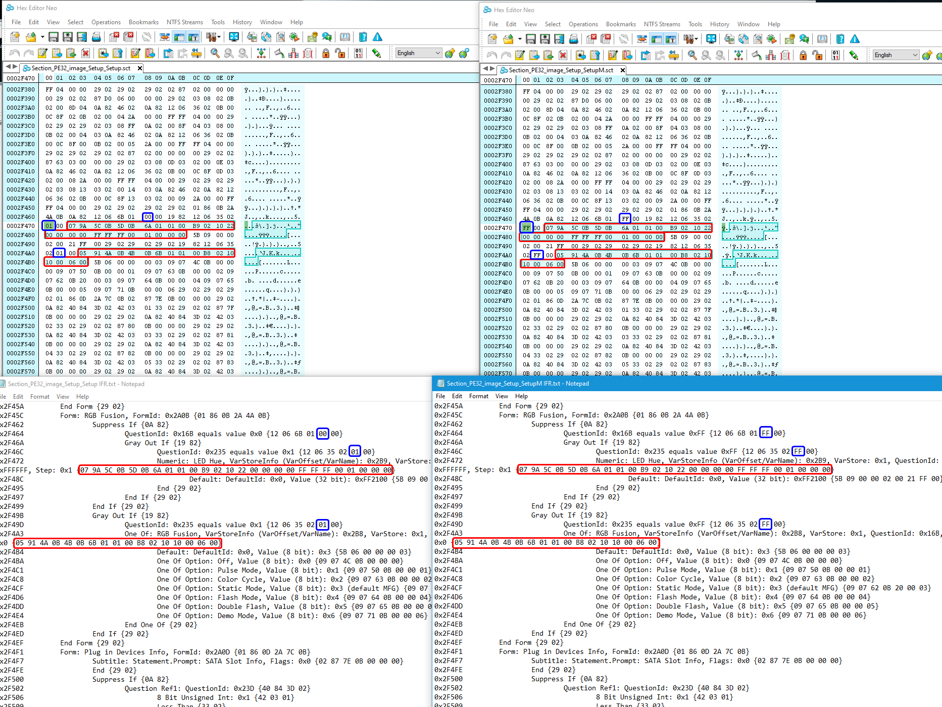
11. Once done, save as final Setup PE32 modified module, then generate a new IFR and double check your work to ensure IFR is generated properly, and that where you meant FF’s to go, you see them in the new IFR.
** Side Note ** - On IFR generation, sometimes the programs may crash or freeze, just close and try again.
This is normal and can be random, to avoid this sometimes it helps to browse to file, open and wait 15-20 seconds, then hit extract and pick/name filename and wait 15-30 seconds again and then save.
Any new post-edit IFR should be exact or near exact size as original
If you hear CPU load / fan speed up and it’s frozen then = bad edit was done and HUGE IFR will be generated >> size will increase non-stop until you kill the program 
When it’s bad, and you hear CPU load hit full tilt, then you know a 50-100MB IFR will be generated before you can kill it.
This means bad edit, no need to keep trying to make new IFR, check your edit in hex and fix, then make new IFR again once fixed.
Now, to integrate your modified Setup PE32 edit back into your mod BIOS
1. Using UEFITool 25.0 - Open your modified BIOS file that you edited at first step to disable Qflash back
2. Go to Setup (GUID 899407D7-99FE-43D8-9A21-79EC328CAC21) - Expand to and select the PE32 Module
3. Right click Setup PE32 Module, select replace AS-IS and replace with your modified Setup PE32 module.
4. Save as modbiosname.stockextension
5. Flash via Qflash and enjoy the fruit of your labor