Hello, this might be a guide for those who have bricked their asrock boards of bios update, and it does have SPI_TPM_J1 Header. I noticed that SPI_TPM_J1 is a combination for TPM and SPI, which means in theory it could be “Hot Flashed” by any means. I didn’t find any documentaries or proof if its able to be hotflashed with the SPI_TPM_J1, but what i do find is from my Manual Book, finally i RTFM for this purpose. I do this because i want to remove AmdSpiRomProtectDxe so that i could use flashprog/flashrom for bios dumping and others.
Asrock used to have BIOS_PH1, and any spi programmer could flash it with that header. But now it moved to SPI_TPM_J1 (to me, more like a hybrid of tpm header and bios_ph1), and after reading the Pinout i had a thought “what if i use those for flashing”, so i bought a 1.8v adapter since im on AMD system, and some cheap arduino cables. I found this interesting review in japan, but the pin connected to the cable is tied so i couldn’t see it clear, and i’m a bit unsure if its pure CH341A or if it’s CH341A connected to raspberryPi, so i thought “Hey, lets give it a try”. Board tested: ASrock B550M Pro4
Here is what you need:
A spi programmer (anykind, if you could, buy the ones that support Quad SPI for faster R/W)
1.8v Adapter if you use CH341A (1.8v only needed if the bios chip is no more than 1.9v/2v. So if your bios chip is 3.3v then it wont be needed)
2.0mm pitch arduino jumper cables. 2.54 could fit but it requires a bit effort (like i use on mine)
To flash it using spi programmer, you MUST:
Power drain your pc (or else the bios chip wont get read), so unplug PSU + take cmos battery off, push and hold the power button in your pc for 11 secs.
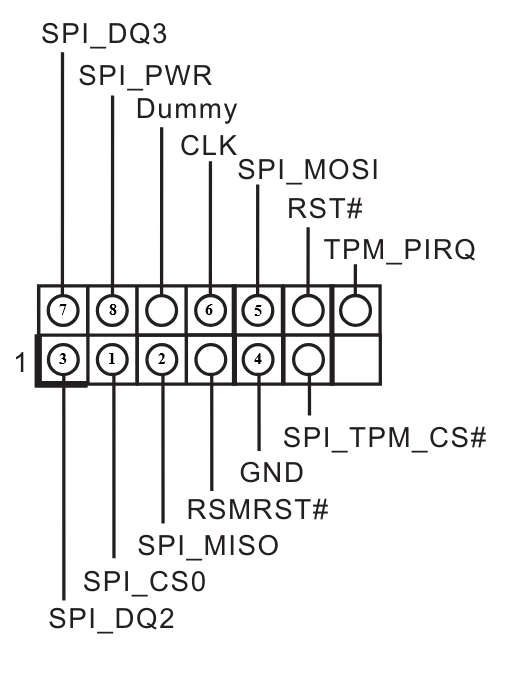
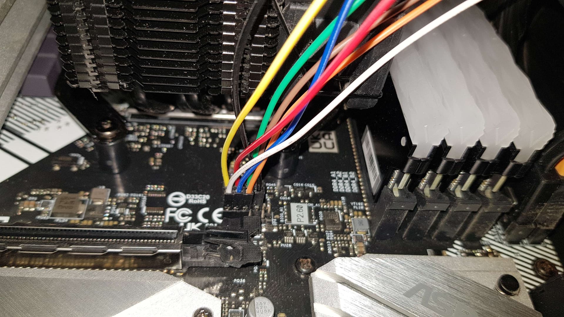
Then, connect and allign the pins on the SPI_TPM_J1 to the Programmer matching the schematic i gave (might differs for non CH341A, but the info for “which pin is which” is there)
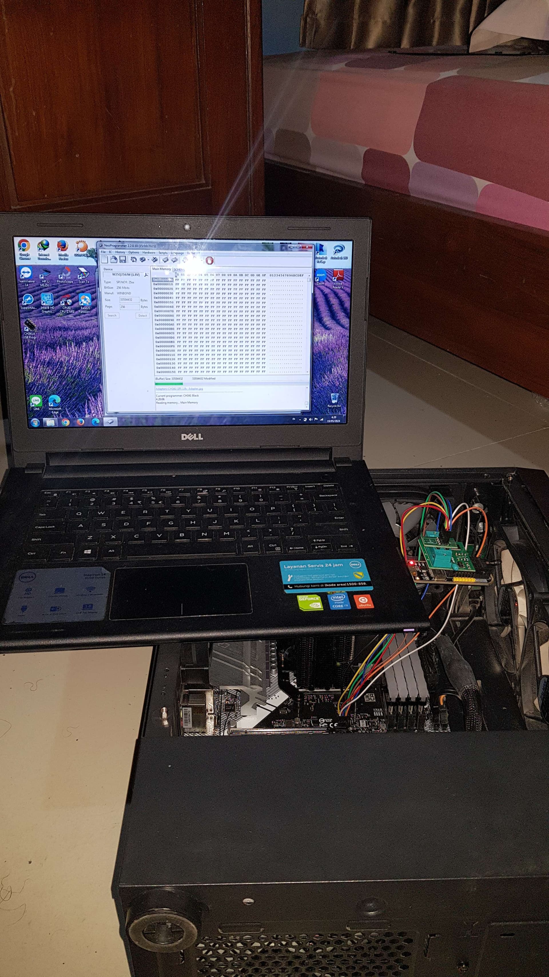
After you’re sure the programmer and the cable alligned, no power is flowing to the board, plug the programmer to a pc/laptop. For programming, i use NeoProgrammer 2.2.0.10, since it supports my bios chip.
Surprised not more people are talking about this all youtube videos are about connecting directly to the chip with a clamp when it’s much easier with an SPI header
I want to say that, though I followed the guide, connected the programmer to the nearby SPI TMP header, but I tried both ch341 and RT809F programmers, triple checked the wires, the programmer can not read the chip. (It’s the ASRock X570 Steel Legend).
I ended up desolder the chip using hot air gun, programmed it with RT809F, solder back and the board is back to life.
Thanks to ASRock, this “legendary” board doesn’t have dual bios, doesn’t have bios self healing feature,and the BIOS chip is a special 25Q256JWEQ 256Mb large chip your usual programmer software will not support, that use a special 1.8V which your normal ch341 programmer will not support without the 1.8v adapter, and it has a special WSON8 package which is again your normal ch341 package doesn’t have support for this. And plus, ASRock put it into a position near the PCIE hook which is a bit of challenge to desolder and soldering back without damaging the nearby components or plastic. And ASRock is known for its very confusing chaning bios revisions that often stop supporting old cpus when upgrading the bios, very hard to understand bios revision histories change logs.
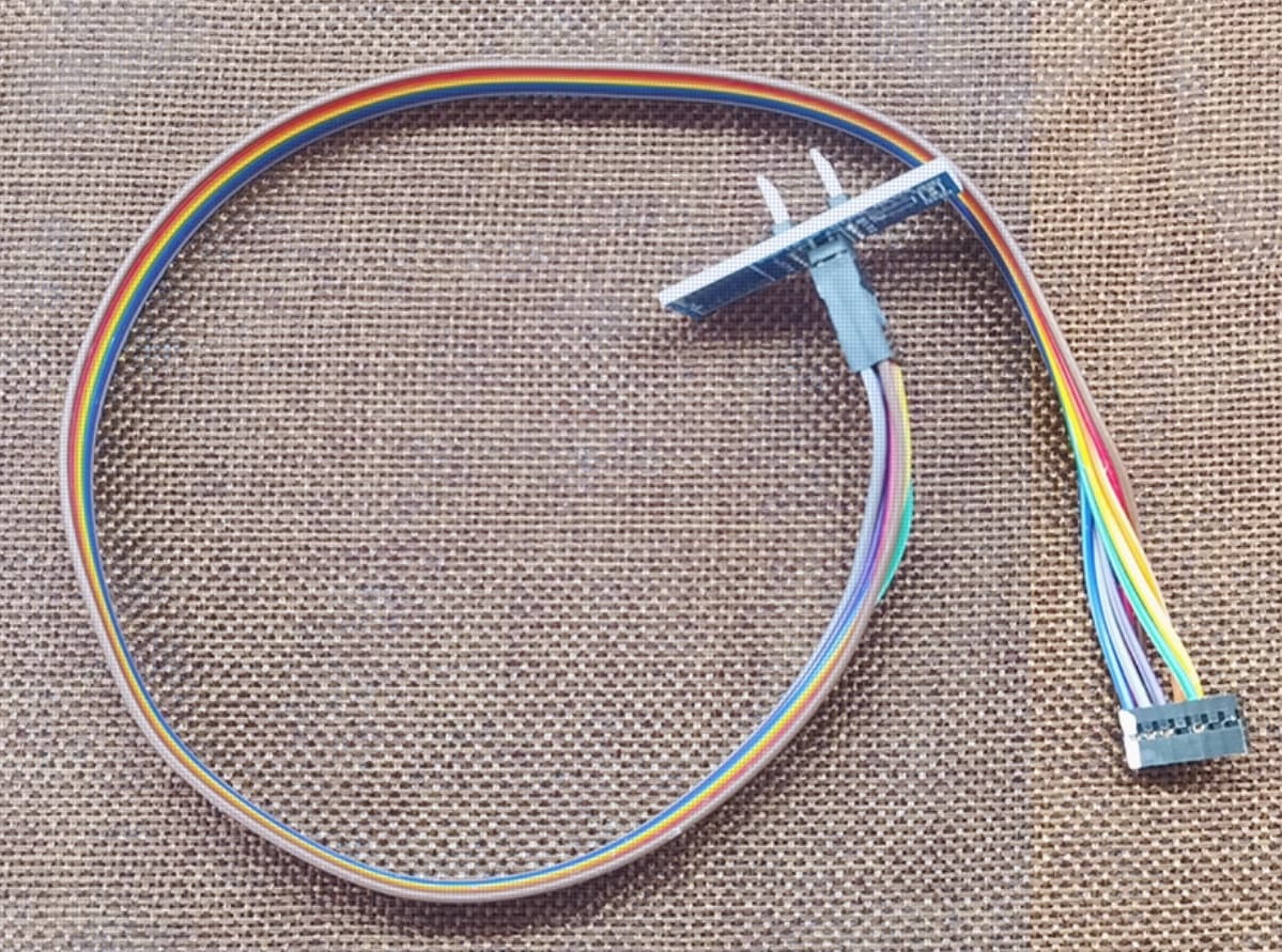
btw since I spent time study this problem, for the people after me, now there’s specially made direct SPI-TMP connecting cable made for each motherboard brands, like this (costing $2 USD each for large quantity)
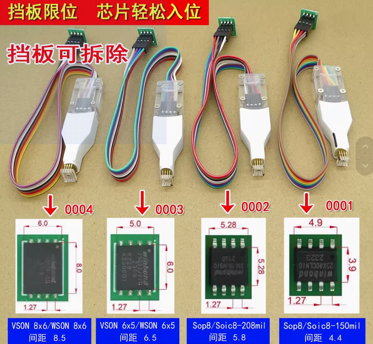
Also for the special problem making WSON8 package chip, there’s now better handling tool letting you flash the chip directly without desolder it or using SPI-TPM header cable like this:
I did what i did because there were no seller in my country that sells those kind of clips yet, and importing stuff is complicated (import tax is crazy).
The guide i made was based on my discovery, so maybe it might be different for you, need to test each pins to the solder of the bios chip legs if you have a spare board to test on, also this guide could be one example on how do you hotflash a mainboard that does offer the spi pin header or spi-tpm combo header, the thing is how and which to connect, it doesn’t always necesarily to be 1:1 with my guide, but knowing if the pins does connect to the spi chip directly and if they need a layout, this could be a good start, since the basic is “how to connect the programmer correctly each pins as if i am using the programmer directly, but now i use cables and connect the wires to the supposedly direct connect to the chip itself”. I used NeoProgramme due to my experience having good success with it, so yeah sometimes this is a hit and miss, good thing your bios chip werent destroyed in the progress.
This kind of method usually needs the cmos/cr2032 battery to be pulled off the board, and the psu isnt connected/supplying power and not storing power (hence i said you need to drain the board power), so that it might not make the bios chip write protect enabled/at high, there are alot of spi flashing guides in general, so you could guess on thr cause of you didn’t succeed with all the variables in your testing.
Thanks for your report, i appreciate it, and im sorry for the very late reply because i barely do any bios modding lately, been so busy.