No adapter needed for that Gigadevice chip.
Yes, maybe, if you flash correct EC FW to EC chip, then system will start possibly
But not 100% sure because I assume BIOS needs to match EC and you have not updated BIOS to that new version (only EC), so BIOS would still be older version and you’d need old matching EC FW to go with that BIOS, unless you also update the BIOS. You may be able to update BIOS though, once you get proper EC FW in there
I don’t know what 2574033E is, you’d have to have 1.8v adapter and dump it then we could possibly find out.
I am looking at BIOS with hex editor and UEFITool 51
Other # on chips are usually batch info, manufacturer dates etc.
Sometimes it may tell some specifics about the chips functions, depends on chip
The BIOS.ALL file I flashed to chip #1 is from the same download portal as the EC FW I downloaded. Pretty sure they’re both compatible as they’re the latest version. Surely this means I already updated my BIOS through the CH341A SPI Programmer?
However, you did say that the order might matter and I believe EC FW should be done first. I can always re-flash the same BIOS.ALL back after flashing the EC FW.
I’ll make sure to get a dump of that chip and run it by you before writing to it though. ![]()
Yes, if you think you;ve got both updated to what’s on the site then that’s a match and should be booting. order does not matter here since you are using programmer
Dump the EC FW chip so we can confirm what’s in there.
Hello all,
I have a fried asrock X370 killer SLI , i have followed guide to flash the bios from asrock (5.10) but unsuccessful with both linux and windows (xp,10)
my question is
1. i need to extract the bios from a capsule or something like that?
Bios (Macronix MX25U12835F 1.8V)
(ASROCK X370 KILLER SLI)
Best Regards
@Lost_N_BIOS
@u535 - Use ASProgrammer 1.41 and MX25U12835F ID - https://github.com/nofeletru/UsbAsp-flash/releases/
BIOS is not in capsule, it’s just bin/rom file. Program in 3.10 ROM and then update using Instant Flash according to the directions on the BIOS download page per CPU and or which BIOS need to be flashed first, before other later BIOS can be flashed in.
You do have to have 1.8V adapter, in case you did not know 
Hello again.
I realise it’s now been over two weeks, but I’ve finally got my laptop back to do some more testing. I just booted up Ubuntu Linux and dumped chip 2 (refer to previous labelled image).
I’ve uploaded the file here: https://ufile.io/3xej0crm
I also received this message when creating the backup:
“ Using clock_gettime for delay loops (clk_id: 1, resolution: 1ns).
Found GigaDevice flash chip “GD25Q10” (128 kB, SPI) on ch341a_spi.
===
This flash part has status UNTESTED for operations: PROBE READ ERASE WRITE
The test status of this chip may have been updated in the latest development
version of flashrom. If you are running the latest development version,
please email a report to [email protected] if any of the above operations
work correctly for you with this flash chip. Please include the flashrom log
file for all operations you tested (see the man page for details), and mention
which mainboard or programmer you tested in the subject line.
Thanks for your help!
Reading flash… done.”
@TheCM - this is 2114A FW, so does not look like EC FW, contents do not look similar nor does naming scheme match. So this is some other items FW chip, or wrong contents flashed into chip etc.
Any other chips on the board? We really need someone else to dump that same chip, so we can see if contents similar, or if it really should be EC FW in there.
Well, I’ll have to wait for the adapter to arrive before testing the other two chips.
Yes, we’ve discussed the number of chips already?
You were suggesting I dump this chip.
I refer you back to these images. The other two chips require the 1.8v adapter, so once I get that, I can provide a dump of both.
@TheCM - Yes, but I forgot Maybe 25D10BT is correct, but dump is corrupt due to how you dumped? Please dump it how I mentioned on post #177 so we can compare, try all 4 methods mentioned and send me the four new dumps
I guess though, it doesn’t look corrupted, I can read it, but maybe some of it should not look like EC FW and that part is OK, but the EC part is corrupted. Hard to know for sure, best we do other dump methods to compare that way we are sure.
MX25U4033E is the only other one that looks like it would be FW, but 4MB is way to large for EC FW chip, so I doubt that is what is on there, but I guess we shall see once your adapter arrives.
What makes you think you need 1.8v adapter to dump 3940S-A chip? That doesn’t even look like a chip that would hold contents, but hard to know without dumping it.
@Lost_N_BIOS
I downloaded the archive and there’s all these. How do I use them? I’m trying to run them in Linux, but the Driver one failed.
Are there instructions for how to use them? Starting from the beginning (just downloaded them).
And quoting you on #177:
So I just need to use these five programs. I’ve put the ones I think you mean in bold. The question is - how?
And you mentioned before that the other two chips needed the 1.8v adapter. When I connect the SOIC8 clip to 3940S-A 745GB the fan starts spinning, but nothing lights up like with the two chips I dumped. It also can’t find it when using the terminal.
MXIC 25U4033E M1I-12G doesn’t do anything when connected, however it did find it when using the terminal - no adapter needed. I wasn’t expecting this, so here’s the dump file: https://ufile.io/ipo0ts68 (524.3kB)
I’ve been using this command from page #1:
--------------------------------------------
The 1.8v adapter I ordered arrived today - although I’m having trouble getting it to work. I’m pretty sure I have it set up properly, with the SOIC8 clip pins lined up the same way as they were in the ch341a programmer and the adapter in the correct slot and oriented the way written on it.
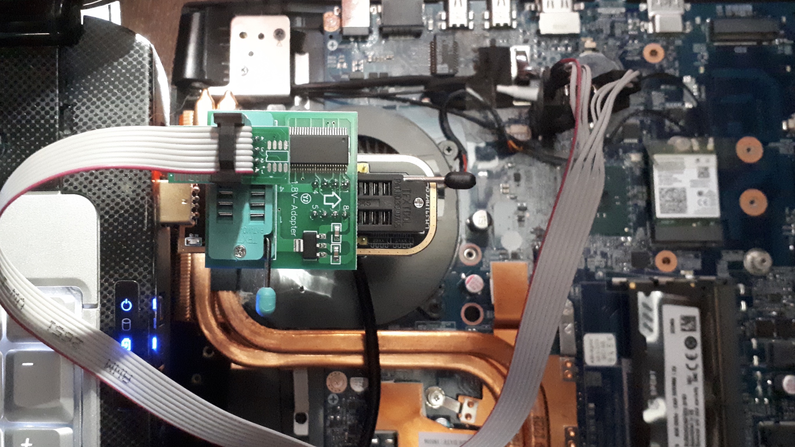
I can’t get any successful reads with it. I did try moving the SOIC8 clip pins to the other half of the adapter in the light blue part (the opposite position to that in the image) and did get one read which displayed this in the terminal:
This might just be because it was in the wrong slot? I’m not sure. Is that even possible? This is for the chip labelled 3940S-A 745GB.
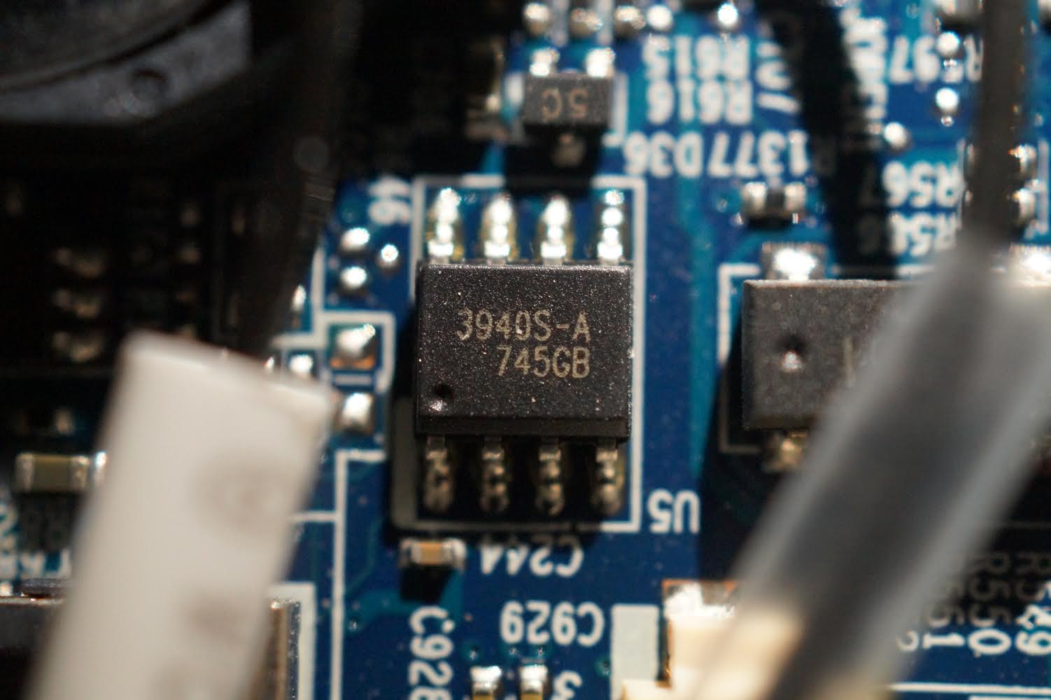
Also, according to this page, that chip might be a linear fan driver, so not what we’re looking for. In fact, as I mentioned before, when I connect the programmer to it (without the adapter), the fan spins. This seems like it’s a mystery solved!
So since I’ve gotten a read from every chip (except this fan driver), I don’t think I even needed the 1.8v adapter unless it helps with writing to the chip (with reading being possible without). Maybe OP was right about it only being for AMD boards as suspected.
Also, I’m still unsure on how to use the other programs as explained above. I’ve been holding off on writing to any chips until I get the okay from you. Hoping you’ll get back to me soon.
@TheCM - These are windows tools. So many is included in package because some chip ID’s need certain software or versions etc.
General guide for the basic CH341A software is here - [GUIDE] Flash BIOS with CH341A programmer
Run from windows, and yes, what you put in bold is what I meant, for whatever chip ID I was talking about right then only.
As I mentioned, I don’t think all these are chips you can read, so not sure why you thought 1.8V applied to all. I think 3940S-A 745GB is a fan driver chip, as you mentioned.
Nothing is AMD board specific 
MX25U4033E is 1.8V chip, adapter required to dump and or write to this chip.
Looks like you may have the clip in wrong place in the adapter itself, needs to go into slot back by lever,
The adapter is labelled telling you which is pin 1 and such. It has an arrow also. It seemed to imply that it goes the way I have it in the image. However, as I mentioned, I only got a read on 3940S-A 745GB when I put the SOIC8 clip into the pins nearest to the adapter like you just mentioned, so you might be right. This fashion seems to be the opposite of the clip+programmer on its own, as the pins closest to the lever are labelled as EEPROM on the programmer and unlabelled on the adapter.
I think the point was that if you have an AMD board, you’re likely to need the adapter, otherwise it’s unlikely.
This is incorrect as I already provided a dump for this chip without the adapter. I also cannot get a read on the chip with one. I don’t think you’ve checked this file yet.
So unless it only affects writing to the chip, I think the adapter isn’t needed.
How do I run the programs in Windows? Just click on them and literally run or do I do it from the command prompt?
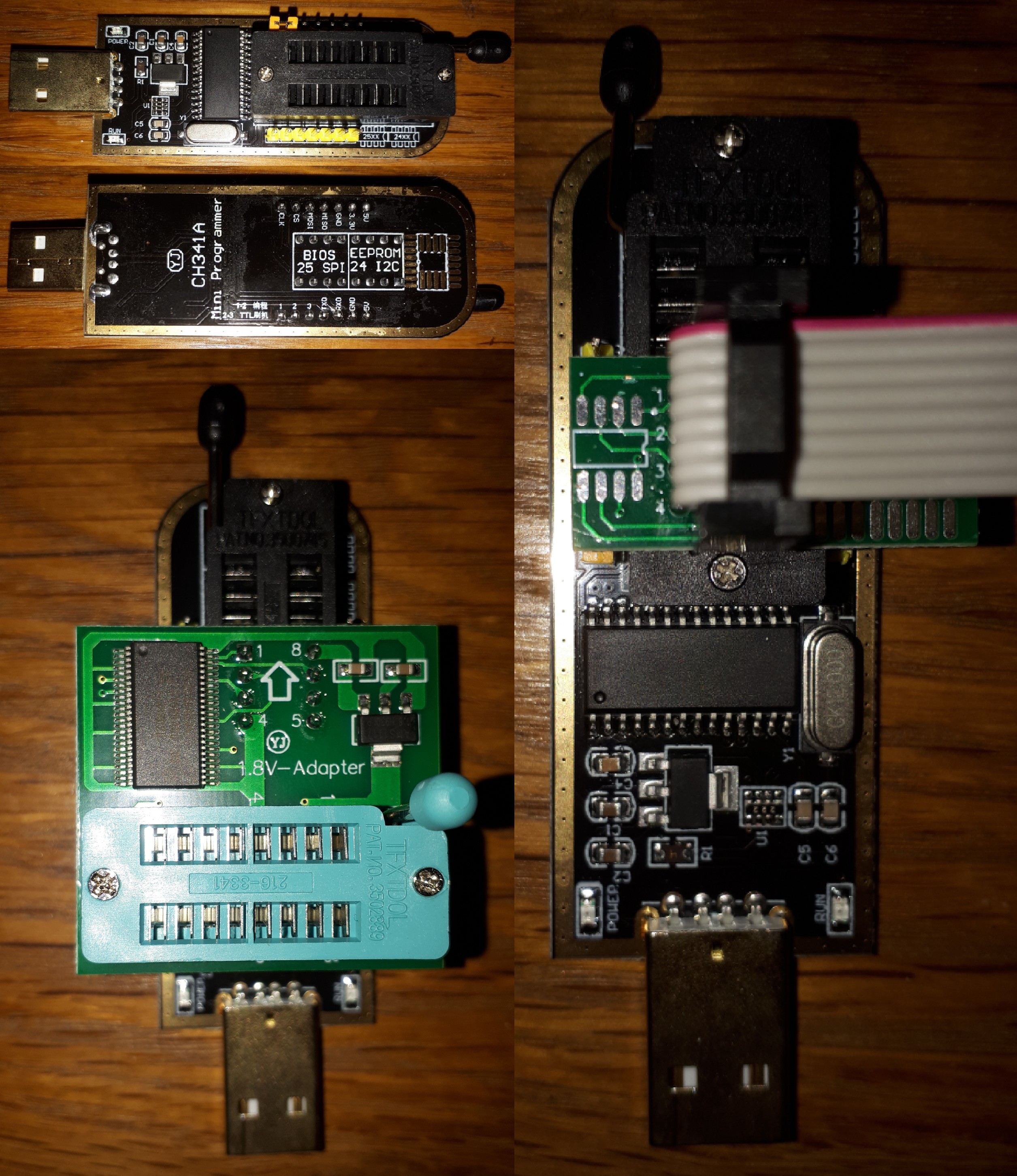
Yes, I know, I have one. The label is for the pins underneath to go into the programmer, not for where you connect the cable into the adapter. If you look at bottom of PCB, you can see traces only come out from the other pins (the opposite of where you have cable)
AMD was mentioned because AMD is a pain for mod BIOS in some cases, and flashrom or programmer is only way. Intel can use many ways, including flashrom or programmer etc.
MX25U4033E is 1.8V chip, any dump you provided previously is likely to be corrupted (read and write will fail without adapter), as I mentioned to redump this once your adapter arrived.
You can look this chip up and check the PDF, it’s 1.8v chip, first result in google.
To run programs in windows, first you install that one driver, then you run each programs exe like all other programs No command prompts here, all GUI
I was thinking there might be subtle differences between them and just wanted to make it as clear as possible what I was doing.
Did you check the other file to see of it is indeed corrupted? No errors were displayed when I read it.
Anyway, I’ve managed to get another read on MX25U4033E, this time with the adapter. Here is that new file: https://ufile.io/bb070qhs (524.3kB/512kB)
I’m going to try and get some separate dumps of Gigadevice 25D10BT using the programs you sent me in Windows. I’ll update you when I’ve got them (if I get it working)!
Also, I want to thank you for being so helpful. It’s not fixed yet, but your help has been invaluable so far. ![]()
Live updates:
* I’ve successfully installed the driver.
* Running CH341A programm v1.34 - I managed to find 25D10 (minus the BT) and have read it. File added below.
* Going to try out another program.
* Using CH341AFree. Upon using the Detect button, it displays ‘Chip Info: C8401110’. Not sure what that means, but I’ve read the chip and created another dump. File below.
* Running CH341 Programmer v1.1.1.32…it’s in Russian! Using Google Translate, I pressed the button labelled ‘Identify Chip’ - it’s displaying the chip as 1 MBIT GD25Q10. Managed to find the read chip and and save file buttons - fortunately GUI layouts are relatively similar, despite the language barrier. File below.
* Tried to run Colibri, but despite showing in the taskbar, it’s not responding (as seen in task manager). No windows coming up, except for the Windows one asking for confirmation to run.
* Using AsProgrammer. Had to select CH341a under the Hardware tab, but managed to find the chip. It listed this info:
Current programmer: CH341
ID(9F): C84011
ID(90): C810
ID(AB): 10
ID(15): FFFF
ID(9F) is the same as what CH341AFree showed (minus the 10, which is also ID-AB), so that’s interesting.
I went to save it, but it wanted to save as a ‘.’ file, aka no file extension, so I just added .bin when saving and it seemed to save just fine with that extension. File below.
* Lastly, Colibri. I’m still struggling to get it to work. I’ll update if I do, but I’m not hopeful.
Ch341a AsProgrammer_1.4.1 - https://ufile.io/hb0dr05z
CH341A programm v1.34 - https://ufile.io/lxmu86s8
CH341A v1.31(1.4) (CH341AFree) - https://ufile.io/objyi4bd
CH341 Programmer v1.1.32 - https://ufile.io/005kn7da
Colibri_program 1.0.1.61-CH341A - Not available yet
So that’s 4/5 new dump files from separate programs for chip 25D10BT as requested. Also the dump file from MX25U4033E using the adapter. Hope this is what you wanted ![]()
@TheCM - Yes, I looked at the file you sent before, as I mentioned. No errors means nothing, you wont see any errors in hex editor with any file, corrupted or not, so I’m not sure what you expected to see error-wise
I just wanted proper 1.8V adapter dump to comapre with, to see if same/dif, etc so we could at least be sure of it looking “OK” as we could Thanks for the new dump, I will check it out.
You’re welcome! Hopefully we can fix!
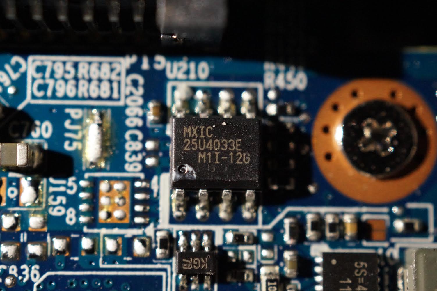
MX25U4033E = vBIOS dump for GP106 GFX Card (1060/1050 + few non-standards - TDP 120W Max), and both files match, so maybe your power level dropped from 3V down to 1.5-2V low enough for read without adapter to be OK
Neither of the vBIOS inside the main BIOS match this, they are both for GP107 card (1050 only + some other non-standard - TDP 75W max). What is your actual card model?
And, if you have the system apart, and have thermal paste handy, might be a good time to repaste the GFX Card, and while you do give me the actual ID printed on the silicon or PCB around the silicon.
Since both could be 1050, maybe it’s best you check silicon to confirm, in case you should have GP107 vBIOS in there? Well, I guess even if you check, we can’t tell if it should be 106/107 since both can = 1050 card  - Not sure what to do there, I guess you can try the other two from BIOS at some point
CH341 Programmer v1.1.1.32, change the language, last menu up top
Save without extension or any random extension is fine. Not sure what’s up with Colibri not working for you? What OS are you using? Try disable anti-virus and close any anti spy/adware programs, in case they are causing issue.
Please package all files into a single zip, thanks
@Lost_N_BIOS
In terms of errors, I was expecting something to come up in the terminal for that chip. However, it recognised and read it just fine. Maybe you’re right about the power level dropping…I don’t know.
This laptop has a GTX 1060 (6GB). Definitely not a 1050.
The repair shop I took the laptop to told me there wasn’t anything wrong with the BIOS, however I’m pretty sure they only checked the main BIOS chip and not the one for the EC FW (I think I flashed the wrong model by accident). They also told me there was an issue with the graphics card, which I had suspected. Specifically that it’s likely gotten too hot and melted the contact points?
It was the main reason I attempted to update the BIOS in the first place (although this was before I got it checked at the repair shop).
I think the issue with the graphics card is a separate issue as it booted to Windows just fine before I tried to update the BIOS. There were issues with the GPU then though.
I could try repasting it, but it seems risky. Right now it’s best we focus on trying to sort out the EC chip to hopefully get it to POST. In fact, I was planning on dealing with it after.
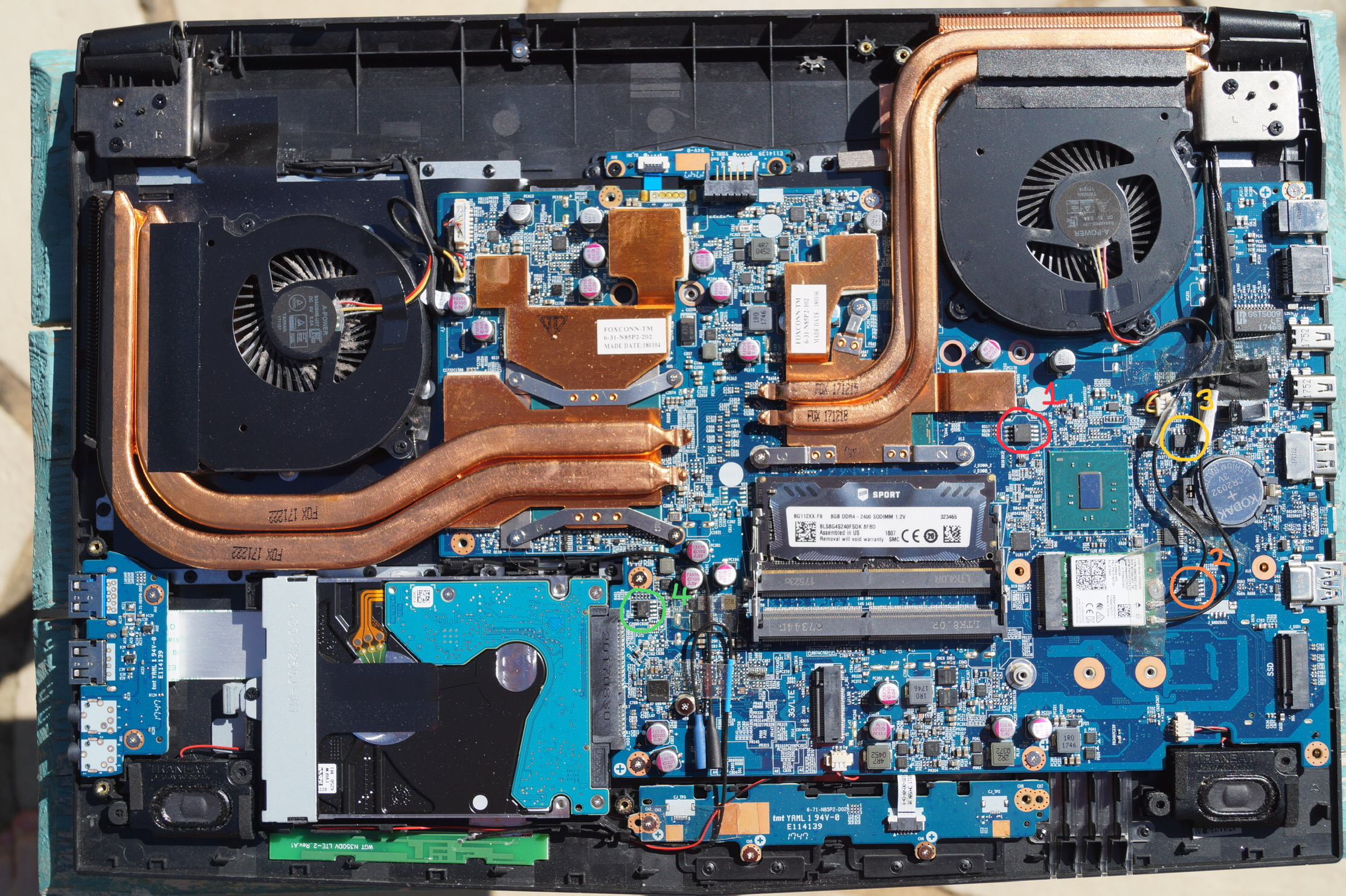
Looking at this image again, we know that:
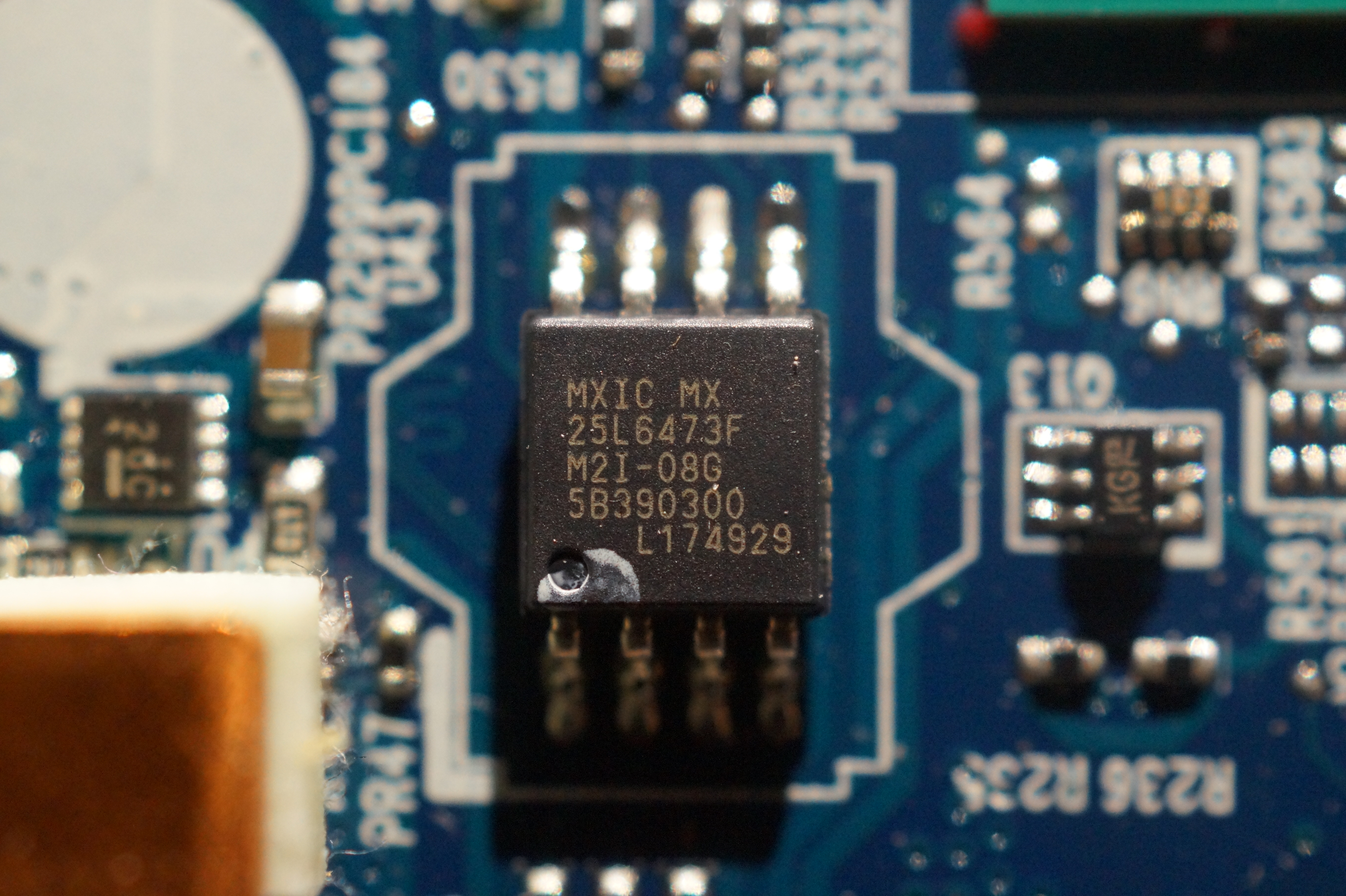
Chip #1 (MX25L6473F) is likely the main BIOS chip.
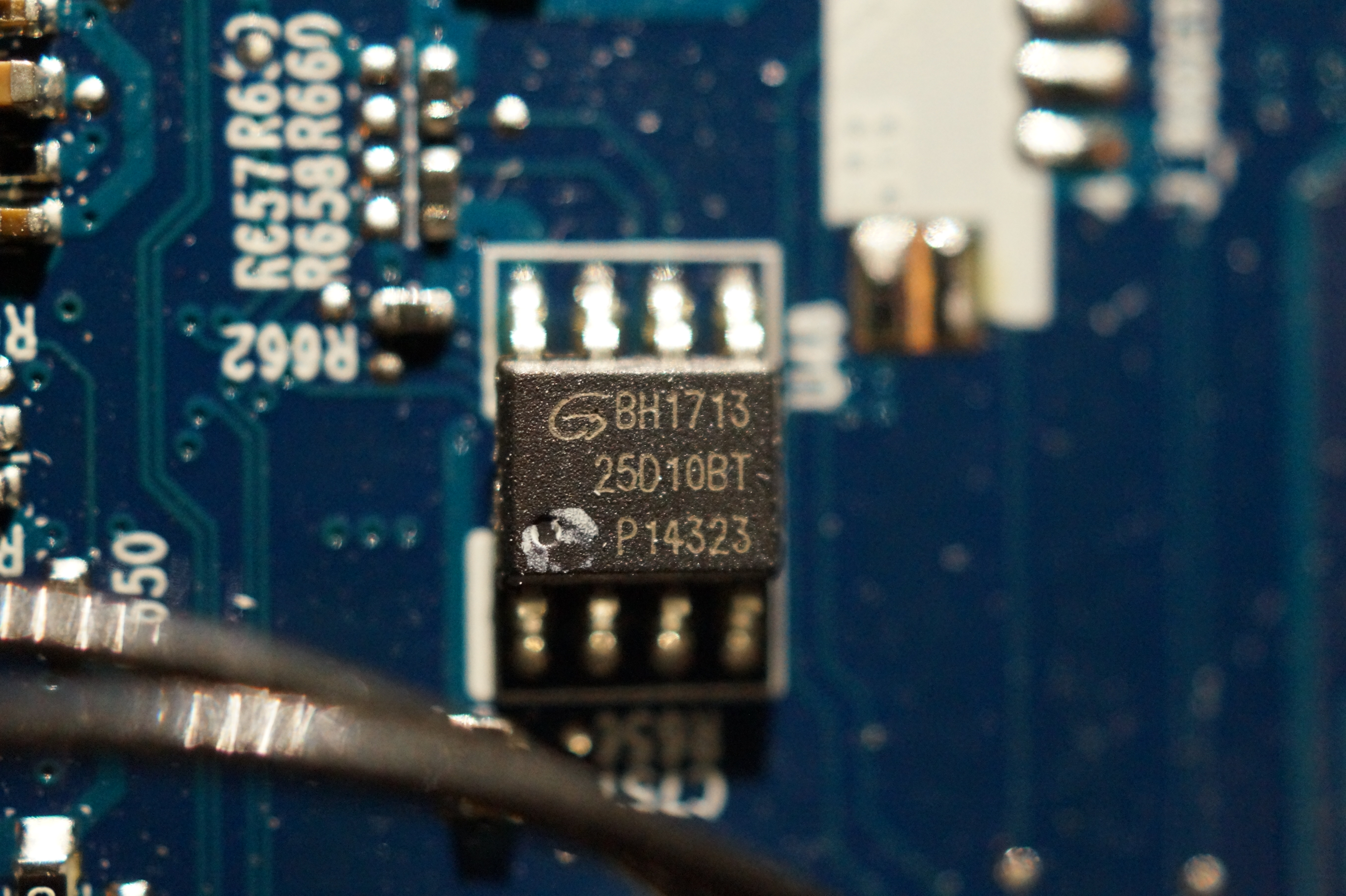
Chip #2 (GD25D10BT) might be the EC/KBC chip.
Chip #3 (3940S-A) is a linear fan driver chip.
Chip #4 (MXIC 25U4033E) is the vBIOS chip.
Can you confirm that 25D10 is indeed the EC FW chip? (Potentially from looking at the files provided below) However, you did say this before:
If this isn’t the EC FW chip, what is?
I’m not sure what changed, but Colibri is working now. Maybe a couple of restarts and a day later fixed it? Either way, I’ve got another dump of that chip. Again, it’s recognising it as GD25Q10 and not GD25D10. According to this datasheet, that’s just the product series.
Here’s that .ZIP of all five separate dumps for GD25D10 (now including the Colibri dump): https://ufile.io/2kwm5w7m
Update:
I forgot to mention - the repair shop replaced the BIOS chip when checking it (at no cost) and I just read from it using the tools you sent me. They told me the hex code was copied over from the previous chip, but after checking for myself, it was completely empty! I created a backup just in case and then rewrote the updated BIOS.ALL file from the download portal.
Of course, I didn’t expect this to fix anything as it was already in this state before I sent it off to them. However, if we can verfiy which chip is EC FW 100%, I can write N85HPTR1.08 to that EC chip and this should hopefully fix my issue. I’m just waiting on confirmation from you.
@TheCM - Re-pasting the GPU is same as re-pasting a CPU, only you need to carefully alternate screw tightening as you go if it’s a bare chip unlike CPU, generally that is done with CPU mount too but it’s far more critical if chip is bare silicon so you don’t crush a corner
If/Since it’s been overheating, this is highly suggested, the old paste under there now is likely crap to begin with, too thickly applied, and is now baked through and old. Unless the repair shop re-pasted it when they looked?
Still, odd to see three GP107 vBIOS in BIOS only, and chip dump off the board is GP106, maybe the repair guy switched your card for a dead card and that’s why he mentioned graphics specifically (so when you found it was dead you maybe wouldn’t notice the switch)?
Or maybe this due to wrong BIOS package you linked me too? I see this only in the stock BIOS package is where I’m looking. What did he say when he gave it back to you about fixing it, was it working then, or he said he couldn’t fix etc, I forget?
Send email off to XMG and ask them which chip is EC FW chip, or where it’s located on the board. No, I cannot confirm 25D10 is the EC FW chip, I can only confirm it’s not or it’s current contents are not EC FW.
Open EC FW in HEX, you will see UUITE Tech near start, this is type of many EC FW. If you then look at current contents of 25D10 chip, this looks nothing like the EC FW.
Nothing under memory, you checked, I forget?
Sometimes EC FW is not on a chip we can read/write like this, but rather one of the QFP chips (Quad Flat Panel), and can only be written to through an onboard header like COM or SPI header (likely not there right now), or via KB ribbon cable etc.
This kind of info can usually be seen in a schematic or boardview file for the motherboard. It may also be EC FW is on the other side of the board, have you looked at the other side at all yet?
If not, do that now. You may be able to see 80% of it with the keyboard removed, but ideally it would be best to pull out the board so you can see it all. And this way, you may find board model # too, then I can try to find free schematic/boardview and we’ll know exactly what’s where then. - See below
CH341AFree dump of GD25D10 - You forgot to pick correct chip size
All these are 100% match except for the above, due to that (it multiplied the contents x8 to fill the space) - This is not EC FW /= >> 2114A_FW 2114A_RCFG
I found the schematic EC/KBC chip is >> ITE 8587 and it’s 128pin LQFP as I suspected See Appendix B >> B-2 & See also B-49 (UART is how it’s accessed for read/write via KB Ribbon cable)
Looks like you can program it through the KB ribbon cable, but I don’t know how you do that
http://s472165864.onlinehome.fr/anyware/…%2020170420.pdf
@Lost_N_BIOS
I agree, it definitely could do with the thermal paste being reapplied. I’ll be sure to alternate tightening each screw as you say when I do. As I mentioned before, right now getting it to POST is priority, fixing issues with the GPU can come later. ![]()
I doubt the repair guys switched the cards, they were only supposed to give us a quote and assess what was wrong. There was already a problem with the GPU before they got it - I just didn’t know what. However, that took almost three weeks as they were waiting on a BIOS chip to arrive - which was a colossal waste of time.
Where are you seeing GP107? Are you referring to this BIOS package from the official site (see Firmware)? That’s the one I have downloaded as I’m pretty confident it’s correct. And since the new chip was blank, the BIOS.ALL file from that is what I have written to the chip. It’s official, so it must be right…surely?
From what I can see, GP107 wouldn’t make any sense as the 1060 doesn’t support that. I can’t think why it would be on there. You say the dump I provided originally is GP106?
Order of events: Bought laptop > Fixed separate issue > Realised there was an issue with the GPU > Updated drivers > Attempted to update EC/KBC BIOS > No longer POSTs - Tried to fix it myself, with your help > Sent it off to the repair shop for a quote > Got it back, allowing us to keep trying > Now.
We were told they used to do this particular repair for GPUs, but it wasn’t reliable and they don’t do it anymore. No, it wasn’t working before or after they got it, only before I tried to update the BIOS.
There aren’t any chips under memory, just info like part numbers and model.
—
That’s both good and bad news. We now know which chip holds the EC/KBC FW, but it’s an entirely different chip type. I hadn’t come across the service manual yet, so thanks for sharing (I only had the User Manual). A lot of useful info in there!
So ITE 8587. What can we try? Is there an equivalent of the CH341a SPI programmer for this chip? You say I can use a KB ribbon cable - would you please provide more info on this? Perhaps I can look and order one. If programming it myself isn’t an option, perhaps I can buy one pre-programmed and just solder it myself? Any other options if not?
I’d really hate to give up here because we can’t interface with this chip. There must be something I can do.