I don’t have Colibri 1.0.1.62, I tested it with Colibri version 1.0.1.61 from your archive.
It was a copy error, then I was looking for version 1.0.1.62!
Anyway, the latest version is 1.0.1.63 from 14.10.2020!
@Lost_N_BIOS - Thank you so much for the reply.
Yeah my old motherboard had 3 shorted components, I will order them and try to replace them and see if it works, I’ll let you know if that happens.
I have already made a thread with all necessary info, you can find it here:
[REQUEST] Lenovo Y520-15IKBN BIOS unlock BIOS ID: 25B64CSIG
And no worries, take as much time as you need, thank you so much.
@ibsajc - Ohh, OK, sorry I thought you meant you had used .62 in your test.
Would be nice to get .63 instead of .62, but I don’t want to register somewhere just to get it
@quattos - Ohh, hmmm, I did not know the other board has shorted out items, that’s not good
Looks like incorrect ID there, but I’ll jump in your thread and check in case you made a typo in title.
@Lost_N_BIOS
Have some questions about #1 (GbE region)!
I extracted the two regions from davidm71’s dump (extracted-from-dump-GbE.bin) and from the last BIOS found on the ASUS site (extracted-stock-GbE.bin).
Try to compare them:
1. offset 00000000 -> 00000100
- differs more than the primary MAC address
2. offset 00001000 -> 00001100
- missing in "extracted-stock-GbE.bin"
- in "extracted-from-dump-GbE.bin" differs from the first block (offset 00000000)
3. offset 00001400 -> 00001780
- missing in "extracted-stock-GbE.bin"
files.zip (828 Bytes)
@Lost_N_BIOS did you receive the dumps for GbE region and BIOS region from @C_con_con ?
If so, can you give them to me too?
I still have doubts about the changes made by my for ASUS Z170-WS as I wrote in post #624!
I have managed to flash SPI chips om the board without desoldering. The best are MSI boards - all successfully. I powered the board, then switched off power and tried to detect chip via clips or SPI cable (there 9-pin SPI port for connecting external BIOS)/ After 2 -5 min the chip is detected and then flashed. The charge of capacitors is enough to ensure flashing by CH341A. Try this method. But Gigabyte boards flashing failed.
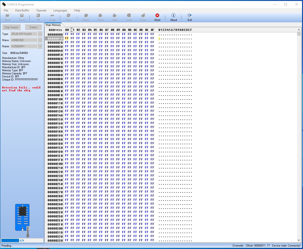
i use ch341a pro for the first time, i can’t programm my bios w25q64fv with soic8 sop8 test clip. but detect chip and flashing programm no work.
solutions?

Unfortunately I don’t have an ASUS Z170-WS, I only have an ASUS Z170-A.
I’ve recently discovered that there are leaked? ("Confidential and not for general distribution.") Intel Network Connection Tools which can change the MAC address and a million other things. I suggest you try those. I don’t know if this works, but you can try:
Download the TOOLS folder and read the install.txt file.
The tool to change the MAC address is EEUPDATEW64e.exe in Winx64\OEM_Mfg (it needs administrative privileges and a driver which you can install by executing the install.bat file).
Read the help: EEUPDATEW64e.exe /HELP
List your NICs and MAC addresses: EEUPDATEW64e.exe /ALL /MAC_DUMP
Change the MAC address of NIC 1: EEUPDATEW64e.exe /NIC 1 /MAC=macaddr
Check the EEPROM checksum and size of NIC 1: EEUPDATEW64e.exe /NIC 1 /TEST
Change the MAC address of NIC 2: EEUPDATEW64e.exe /NIC 2 /MAC=macaddr
Check the EEPROM checksum and size of NIC 2: EEUPDATEW64e.exe /NIC 2 /TEST
Unrelated PS:
Just for reference: I flashed a stock GbE from Z170-A-ASUS-3802.CAP, then used eeupdate64e.efi (via UEFI Shell) to change the MAC address. Only the first 6 bytes of the GbE changed.
The Intel I219 GbE is explained in ethernet-connection-i219-datasheet.pdf in section 10.0. I think only the first 128 bytes are interesting in this case?
I’ve been messing around with my GbE recently. To make my life easier I structured down the bytes of my GbE (with the descriptions from the ethernet-connection-i219-datasheet.pdf) into a .s file which GNU assembler (as) can turn into a binary again. (NOTE: I like the syntax of as for this sort of thing. It’s not actual assembler code in anyway. Just bytes being put together, with a description, in the source file).
Your 2 files (extracted-from-dump-GbE.bin and extracted-stock-GbE.bin) (first 128bytes) were very similar, so I adjusted my files for you, which you can find in the attachment of this post.
I hope this answer some of your questions.
gbe.zip (5.13 KB)
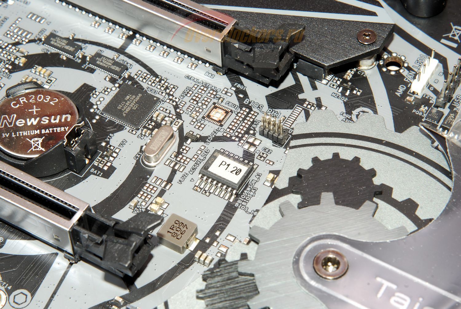
Hi, can anyone know the pinout of the asrock bios_ph1 pad on the Asrock Thaichi X470 motherboard, a flash on the Winbond 25Q256JWFQ board for flashing with the ch341a programmer, thank you in advance for your help.

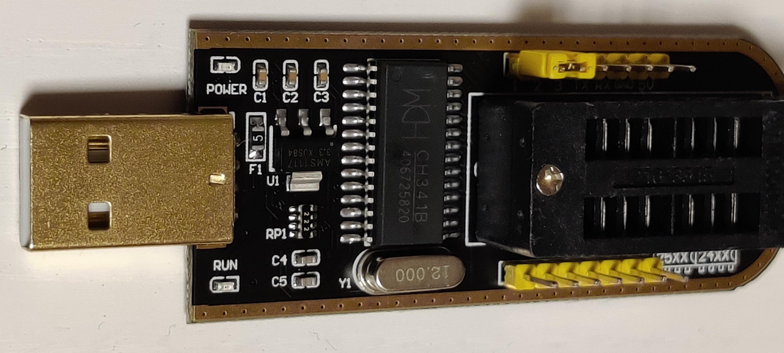
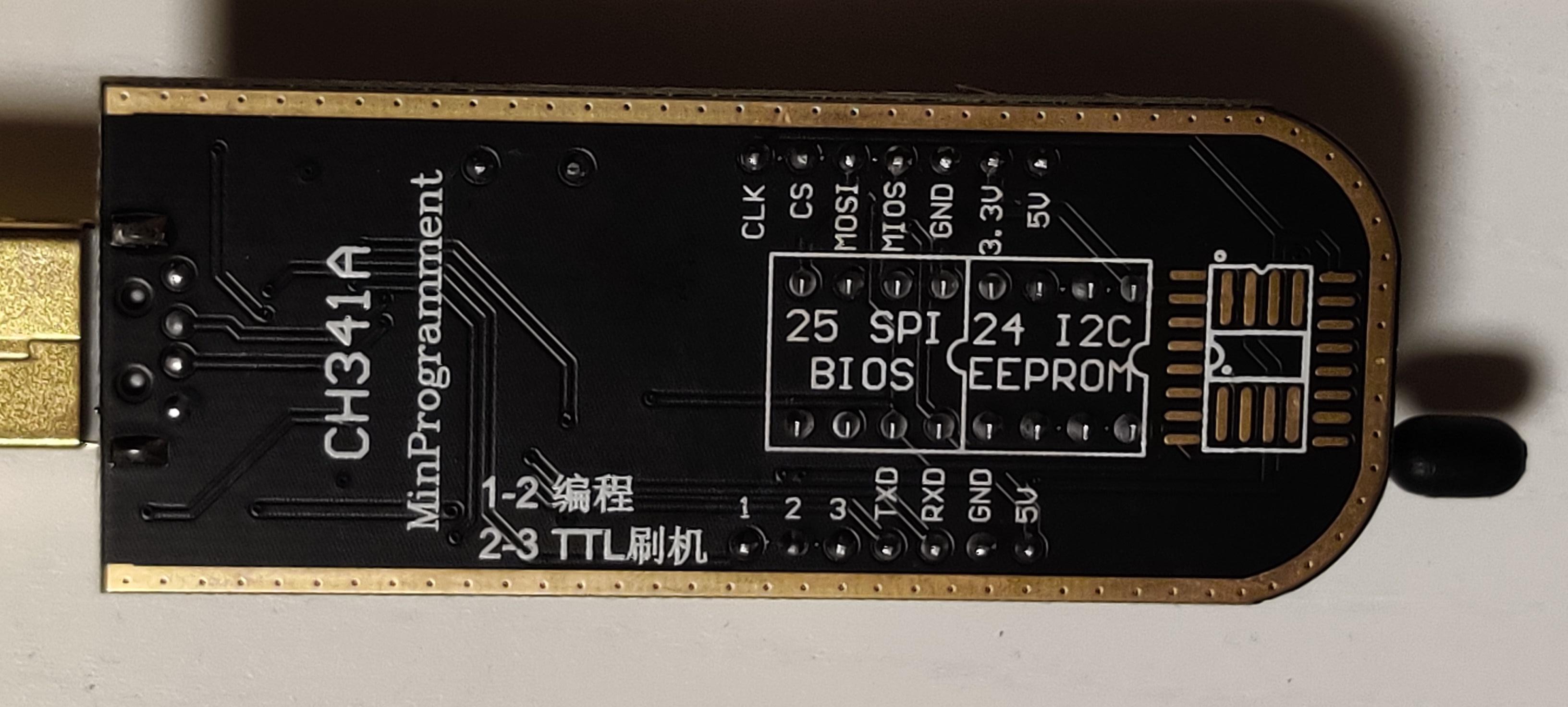
Hi everybody, can someone tell me do I need to do same tweaks on ch341a (but with chip CH341B) like on ch341a with black board? You can see pictures attached. I need it for flashing chip with 3,3V. It would be nice to have some feedback from someone who already flashed some uefi chips from winbond series 25Qxxx.
Edit: on Pin 28 is still 5V like on earlier models.


Which program should I be using on Winbond W25Q32BV for a Dell Inspiron N5110 bios? I’m having trouble getting the chip blanked to reflash it. I either did something wrong trying to fix the corrupt bios or I’m doing something wrong flashing new data
Hello,
Which program should I be using to flash a GIGADEVICE GD25B127DSIG (25B127) chip?
This is the BIOS in my CyberpowerPC Gaming laptop (I7, RTX2070) which is a barebones Quanta NL5E with both CPU & GPU soldered on.
I have downloaded the CH341A programmers versions 1.18, 1.34, 1.38 - but none of these have the 25B127 in the chip selection list.
Any help much appreciated.
Thx,
@pipes80 For W25Q64FV use 1.30 or 1.34 and choose W25Q64BV ID - Or Colibri -
Hope this help.
I have Alienware Area 51 R2. My board bios chip is Macronix MX25L12873F. I kept on getting same error on CH341a app with the correct chip model selected. It is hard to get a firm grip of bios chip using the clip. Clip keeps losing hold and bends pin in proximity. But I managed to have it grip the chip and stand by itself repeatedly. However when try to detect chip, I always get the same “Detection Fails” error. My programmer shows up in Windows device mgr correctly. I triple checked pin 1 is oriented correctly everywhere. I do not understand why it is so hard. Is it really not getting a good contact between clip and chip, or am I missing something? Which version of ch341a should I use?
“This error(s) is caused by the bad connection of the clip or by the wrong software version”
When I use ASProgrammer app, no error and appears to “read” but reads nothing back. The app still “reads” even when clip is detached from chip. How do I use ASProgrammer to check whether my chip is detected or not?
@xps630 ,
just 2 days ago I used AsProgrammer_2.0.0a14 on 2 MX25L12873F in my Z97X-SOC Force and both bricked BIOS chips reflashed successfully with stock BIOS.
How do I use ASProgrammer to tell the programmer clip is having good contact with bios chip? I was worried when ASProgrammer read was all blank even though it did not say error.
Hello
I’ve been trying to flash a Macronix MX25L12873F chip on a Lenovo IQ2X0IH board. I aquired a bios through vinafix.com.
I tried flashing with flahrom and a CH341a programmer but flashrom detected chip “MX25L12805D” or “MX25L12835F/MX25L12845E/MX25L12865E”. I selected one of those options, even though it wasn’t my chip and the flashing was succesful. I tried it and it booted one time perfectley but stopped booting afterwards.
I then read on the flashrom supported hardware page that that chip was not supported. So I tried with the windows programs: Ch341a v1.34 and AsProgrammer 1.4. The chip is identified, erased, and written, but fails on verification and of course, does not load.
Any help would be appreciated.
Thank you
@santivelez Instead of posting same content twice a forum search would have served you better:
@lfb6 I did do the search and already did all of that post, as it was one of the first I found. That’s why I’m posting, cause it still doesn’t work. Looking for help, not complains.
Most often the clip isn’t in correct position. Other (rare) options would be a defective chip or too high current drawn from board, but the latter makes normally the CH341 ‘disappear’. Sometimes not used pins are on 3V or ground which the CH341 doesn’t like. See this post for one possibility: [GUIDE] The Beginners Guide to Using a CH341A SPI Programmer/Flasher (With Pictures!) (3) (pic in spoiler)
What do the lights on the CH341 do? One LED on when connected, the other LED on when writing in addition- or are both LEDs on already when connected?
Did you do a ‘blank check’ after erasing? (At least Asprogrammer has the option)
Did you check the differences in the dumps? Complete blocks not read- single errors?
