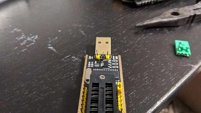
The clip seems to be on the right position. If flipped it will not recognize the chip.
I get one LED when connected and then two LED’s when writing or erasing.
I did the blank check on Ch341 software and it was succesful
I didn’t check difference in the dumps. Don’t know how to do that part.
Still trying on different versions of all the softwares and not succesful. I’ll keep trying.
Not what I meant: Bad contact- not all pins do have good connection- is mostly the problem!
HxD, Analysis, Data comparison, compare (= Ctrl K), F6 next difference down, Shift F6 next difference up. It’s not every single byte, it’s chip length, and if it’s single bits, complete blocks, it’s the pattern in the errors.
Changing software versions ‘wildly’ won’t help here if you have a ‘known working’ combination for this chip. And there’s no better source in this forum as Lost_N_BIOS: If he confirms ASProgrammer 1.4 or 1.41…
As written- the clip isn’t that easy to place, try to fit it properly, take a magnifier to check!
Hi guys, this is my first post. I want to express that this is a fantastic community and there is some very valuable advice here. I was wondering if anyone would be able to help me out.
My laptop doesn’t boot, black screen, fan spins for few seconds then nothing, no keyboard/mouse response or light, but the power light stays on indefinitely.
I’ve got a W25Q64FV bios chip. I had corrupted it last year when a bios update failed, so I got the CH341A programmer, programmed it, and revived my machine.
This time my machine didn’t die on a bios update, it just didn’t wake up from sleep. Anyhow, I thought I’d try a re-flash of the bios just in case because this machine has a history of struggling to boot.
I’m using a stock bin file from the manufacturer to write to the chip. This is the same file that I used to revive my machine previously. I’ve used both asProgrammer and the Chinese software and every time I write and verify, it seems to work 100%. Even if I disconnect from the chip, close the software, then reconnect and read, the dump is 100% identical to the stock file. That’s fantastic. However when I try to boot up my machine again and it fails, the next time I go to read the chip, the dump has changed!
Is this to be expected? Is the bios dump supposed to be slightly different after an attempted boot?
I think my motherboard may be dead, but I thought I’d post here just in case I’m doing something wrong on the bios front.
Certain areas of the firmware aren’t static. Post original bios and read back image.
Thank you for the insight, I thought I should compare the files in a hex editor. I’ll take a look myself and post the files if I’m not satisfied. I just had another lifelong tech tell me it’s 99% the motherboard given the symptoms, so I might just have to accept its fate.
Hi, this is my first post, i´m struggling from yesterday with a Bios chip that I have removed from a Graphic Card Nvidia gtx 1080, the chip is from the manufacturer ISSI and is the model is25wq040 , i have soldered the chip to programm it with a ch341a plus the 1.8V adapter (chip works with 1.8v), as first I have saved an image of what on the chip written was, then i have erased the chip and tried with the chinese software updated at version 1.34 to write a rom image that i have downloaded from Techpowerup, the problem is that with verify i get a fail, i also wanted to try with flashrom but i get from the programm Generic Unknown SPI chip (rdid) 0Kb (should be a 4mb)…
I also rewrite the old image that i made as backup and in this case the verify is successfull…Any idea???
I haven´t found till now this ISSI is25wq040 chip in the compatibility list of any flashing bios programs…thanks
Flashing graphics cards bios isn’t my special, but here someone flashed it with bvflash (not desoldered)
[Guide] Remove UEFI Image from NVIDIA vBIOS
For the CH341- read the datasheet and find a compatible chip
Did you blank check the chip after erasing?
Did you read the content of the chip after flashing it with the new chip?
Did you compare original file and read-back content?
Yes in order i erase the chip, than blank, and i get no errors, after i open the rom file, i write it and then verify, i get an error, in the Programm i can´t select this is25wq040 bios chip…
This is a bit of a longshot. But I seem to be hitting a wall whilst trying to repair a bricked bios on an Asus Z97-P motherboard.
Original and ongoing symptoms of the motherboard:
-Computer starts with Ram / CPU / GPU installed with one short beep
-Computer instantly shows a solid white “-” curser and sticks there
-Computer wont load anything from USB including a Dos drive
-Computer registers if you remove any of these things other than the GPU (it won’t switch to onboard outputs as it freezes before it gets to that point)
I bought a CH341A flasher and went about trying to recover it. Chip Model: (GD25B64BPIG):
-I’ve pulled the original dump from the chip and saved it as per reading through the forums
-I’ve added all the addresses and serial number etc into the new .bin (the same and latest bios from Asus as was originally on the chip)
-Cleared the chip and replaced with the new built .bin file
I’m not sure what I’m doing wrong at this point as I keep getting the same white curser at bootup, I have a new chip on order but I’d really like to solve what I’m doing wrong to learn for next time. If anybody could help by taking a look at the file or setting me on the right path, that’d be amazing.
hallo when i try to detect it comes up with nothing some $$$$ unown etc. it read the chip fine but when i try to programm it says file larger i click ok and after a few sec it says time elapsed. the chip is 25x40bvsig the laptop is toshiba l755-15r and my motherboard DA0BLBMB6F0, the size of the chip is 4mb but the bios bin i found is 4mb (4.194.303). i try it with power and without, any ideas?
Those are specific problems and it’ll be almost impossible to follow different the different problems and the last items don’t have much to do with general CH341 usage.
@WightKnight Did you read back the content of the newly flashed biso chip and compared it to the file you intended to flash? Asus provides a complate bios image and if you flashed this correctly the board should work. If it doesn’t it’s not a bios problem. If more help needed open a separate thread.
I used ch341a 1.34 because this one has MX25L12873F in chip search menu. I find this tool sensitive to poor clip to chip contact. It often tells me no chip detected. Once in a while that error doesn’t show up and I think it detects presence of my chip. But it never displays proper chip model?
When it detects chip, it often gives me error of erase time out after moving from 0% to 30% slowly. Once in a while erase finishes very fast without error, but I am sure it actually erases chip.
Has anyone found clip wire-pin connections highly fragile? These tiny wires can break or get loose from pin so easily. Many times I fail to detect chip only to discover wire has broken off pin of clip at the end.
Hi all. I got my ch134a programmer today and plan on using it on my Dell t5810 bios chip. From what I’ve read there seems to be an issue with the 3.3v supply not being right or not having enough power when using the clip onto a motherboard. I bought an atx breakout board and plan to pull the 5v power and ground right out of the usb socket and powering the programmer with a 3.3v wire and ground from my breakout. Should I have any concerns with this?
Why don’t you just try first? There’s a lot of power on an ATX 3.3 V line, so it might be a lot easier to fry something, especially if it’s the first time you work with the SOIC clip.
Try to get used to the SOIC clip, try reading you chip to get a valid backup, and if that did work try to write to it…
(Check chip voltage before using the CH341!)
I have the issue I can’t flash some edited roms, then I get verify error. Also after x attempts. Erase chip blank write verify.
What could that be ?
The rom is ok according to me analyzer and uefitool.
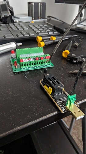
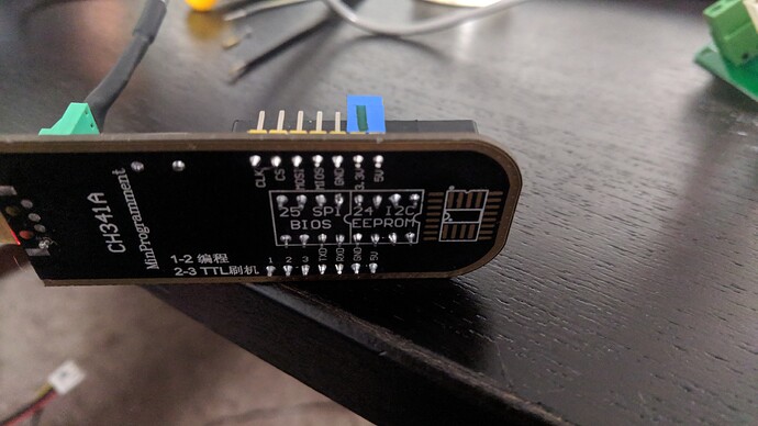
I already new I needed to be at 3.3v. and sorry I jumped the gun and did the mods I spoke of. Worked great at pulling the dump. I powered the system off and yanked the psu and cmos battery and held the power button for a while if that does anything at that point to bleed the system off. It probably took me about 6 times to get the clip positioned right and I made damn sure I was clipped on right on right before connecting it to the programmer. Pulled 3 dumps. I have checked the file size and that they open just fine in amibcp. Still have to check them in a hex editor. Here’s the mods I did to the programmer anyways.
Interesting modification, but some questions:
You cut the 5V USB line and feed it with 3.3V, and shorten the 5V and 3.3V lines on the programmer with the jumper.
- That solves the (possibly non- existing) problem of CH341 beeing fed with 5V and therefore having 5V on the data lines (Vcc, hold, wp are anyway on 3.3V)
- What did you do to ground? Did you cut USB ground, too, or do you have ground connected via both USB and the ATX PSU?
Most people experience probems during writing, but current drawn isn’t higher when writing or erasing for all the chips I checked the datasheet. So I did never experience this sort of voltage drop myself and no one ever checked the voltange on 3.3V line when experiencing proeblems. On tha data lines the current is anyway limited by what current the CH341 is able to deliver… So I’m not sure if this problem really exists, it’s never been prooved.
On the other hand even a small? 400W power supply can deliver up to 24A on the 3.3V line. That might not be helpful in all situations and will make it a lot easier to fry something…
https://www.onetransistor.eu/2017/08/ch3…-schematic.html
https://4.bp.blogspot.com/-nQk5fUPl6fg/X…iprogrammer.png
http://www.anok.ceti.pl/download/ch341ds1.pdf
Your right with the possibly non existing problem. I certainly didn’t know if it was an issue. My concern was not having enough power and corruption. It seems like people that “fried” the bios chip were using usb power and I’m guessing the clip was powered when attached and they shorted pins trying to get it stuck on…maybe. I don’t know and someone isn’t going to post that. Anyways my thought was usb power is enough to hurt it. That’s why I personally wasn’t worried about having all that amperage available because I was being very cautious. What I plan on doing only because I’ve wanted an atx bench kit for a while is encasing everything and have a volt meter and amp meter on every line so I can read what I’m pulling 3.3,5 and 12 for various projects. Oh and your ground question. I pulled both 5v and ground completely out of the usb socket and only used the psu to supply.
Actually now that I think about it I did have a shared ground. The usb socket itself gets solder down to the ground trace on the pcb so even though I pulled the ground pin that doesn’t really do anything…
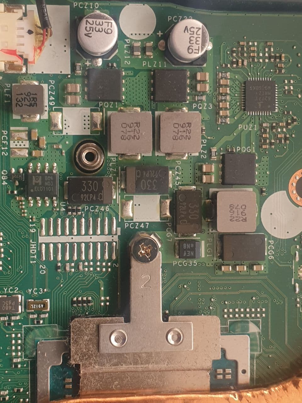
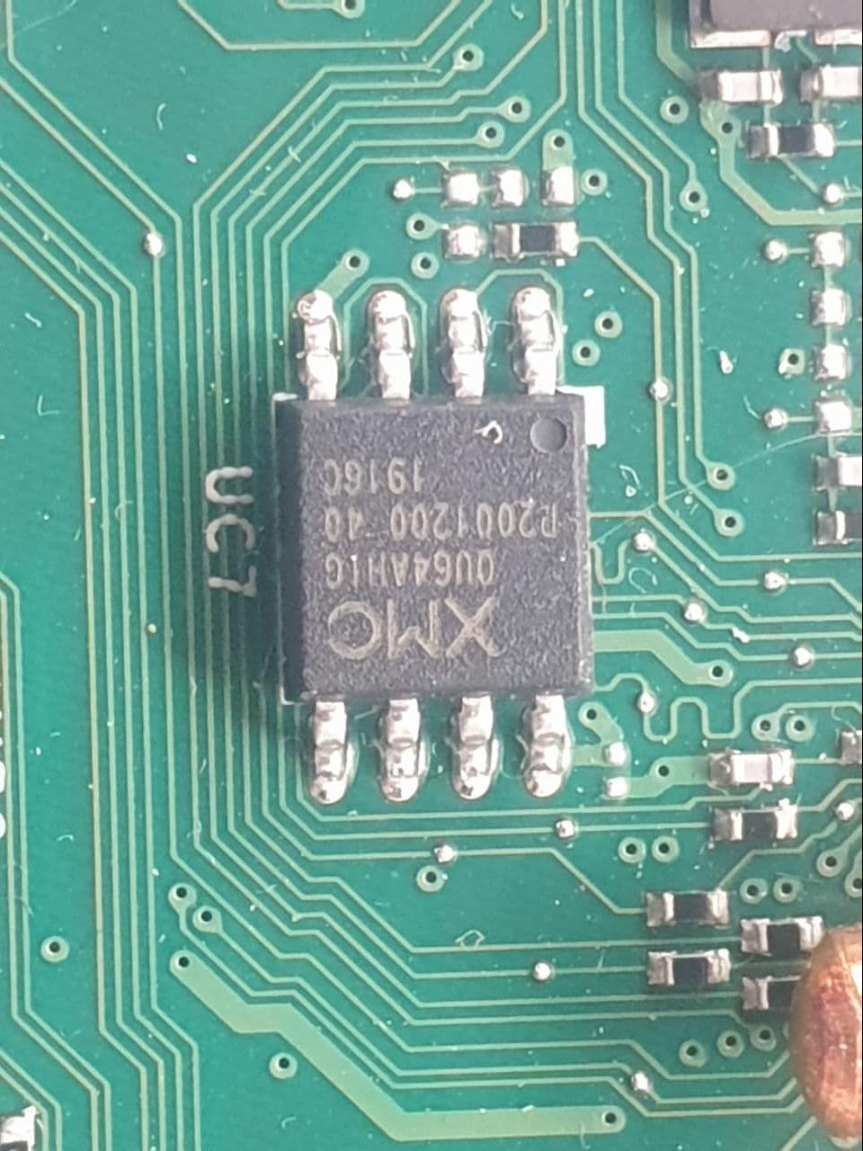
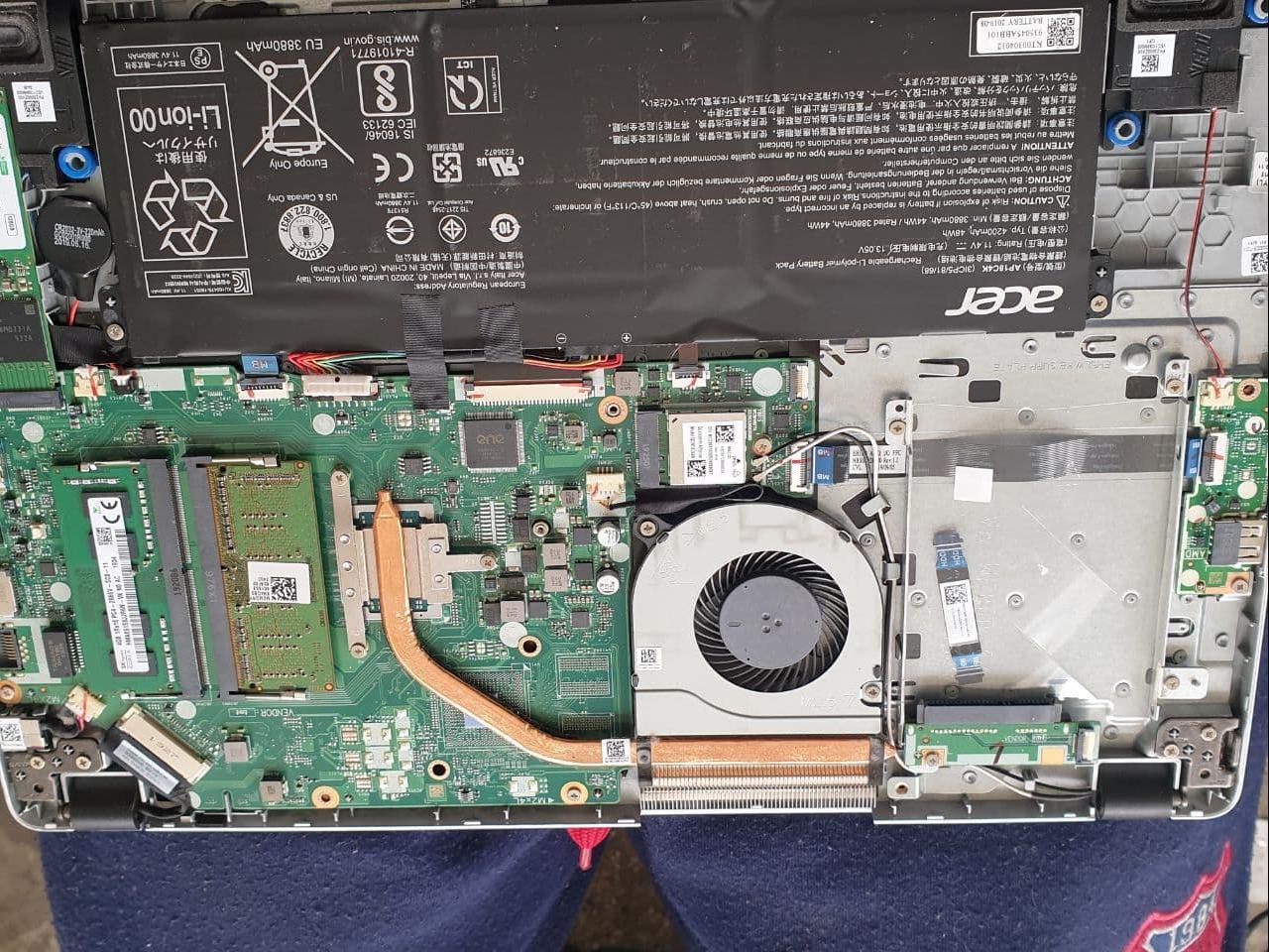
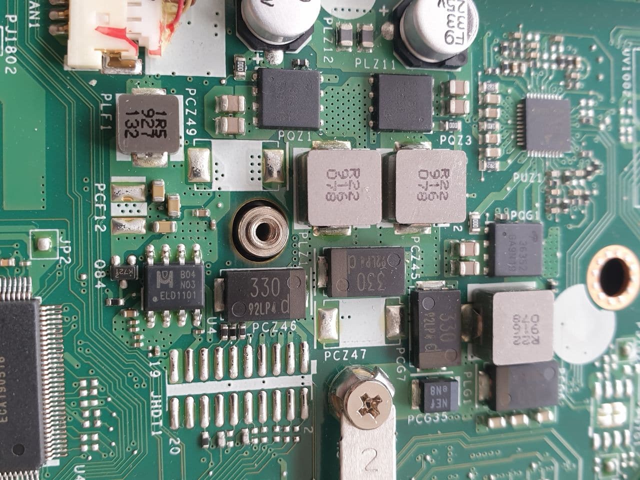
i want to backup my bios from my laptop board (acer a515-43) i have ch341a black one the problem i dont know what chip is the bios and what should i select in Asprogramer
