XMV QU64A is 64Mbit 1.8V flash memory. Might be that it’s not possible or at least not too easy to read with CH341, don’t forget 1.8V adaptor!
http://www.xmcwh.com/Uploads/2018-05-05/5aed274b53c71.pdf
Hello @CodeRush
I am trying to flash a modified bios.
To check the programmer I am trying to read first but every time I read the chip i get different file I am checking hash and it is different . The begging and end of the file seems to be same to the eye but it is different file also the chip itself and the what programmer auto detects is different it is still a Gigadevice 25 chip but the code is different I do not want to brick it. Is there a way to install modified bios on msi laptops without CH341. Can it be just that the programmer is trying to read the whole board and it is the reason and it needs a desolder?
Thanks a lot ![]()
Hi maksover,
here is the picture of the ASRock X470 Taichi pinout.
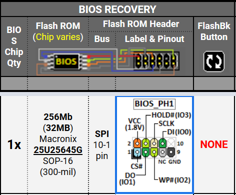
It’s a Macronix 25U25645G (1.8V) chip.
—
I have a question to that: How could I connect my CH341A via 1.8V adaptor to the flash ROM header of the X470 Taichi?
1. Where do I find 1.8V VCC at the green 1.8V adaptor?
2. How to connect SI/DI input (IO 0), SO/DO output (IO 1), WP# (IO 2), HOLD# (IO 3) and SCLK? Edit: Now i know.**
(CS# and GND I’ll find.  )
)
I have a clamp cable SOP16 (300mil), but there’s no connect possible with certain progrmmer tools. I got error, that chip would not be find.
I found this similar thread with almost same config (only cable and chip are different):
https://www.bios-mods.com/forum/Thread-G…341A-programmer
Best regards, MiMo
P.S.
ASRock X470 Taichi Ultimate has Winbond 25Q256JWFQ.
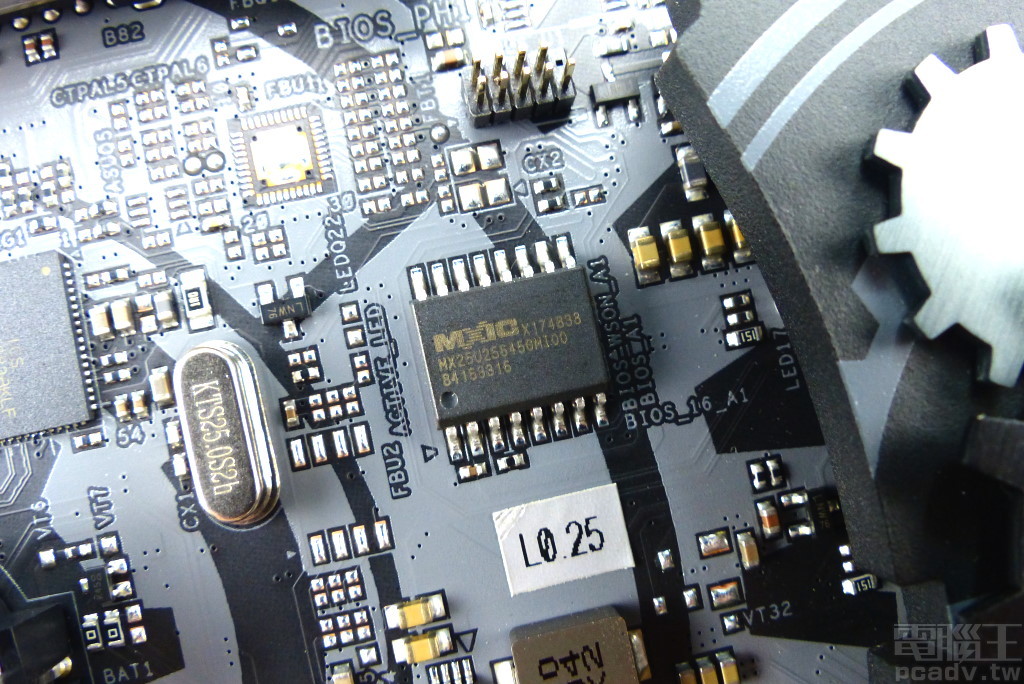
Could you zoom in here & make a screenshot of this area?
Best regards, MiMo
**
It should be connected from the 8 PINs of the CH341a -> to the BIOS_PH1 header (1rst picture below):
(below row)
1. CS# -> PIN1
2. DO/MISO -> PIN3
3. WP# -> PIN5
…do not use! -> PIN7
4. GND -> PIN9
(above row)
…PIN10 is not available
5. DI/MOSI -> PIN8
6. SCLK -> PIN6
7. HOLD# -> PIN4
8. VCC (1.8V) -> PIN2
To program per BIOS_PH1 I need very tiny connectors. I hope I find some in my things or in the internet … 
Hi everyone … especially for ASRock X470 Taichi users!
I found this guide on YT to downgrade BIOS without using dedicated flashprogrammer CH341A: https://youtu.be/ZzqwjVDKAnU
It’s because all programmers I used couldn’t recognize the MX25U25645G. This chip is not included in one of the databases of CH341A Programmer v1.18 - v1.38, ASProgrammer 1.41, 2.0.2.13, 2.0.2.14a or Colibri.
The chip has 32MiB amount of space, but it contains 2x 16MiB parts like in RAID-mode.
The original BIOS from ASRock contains (unpacked) 16MiB.
Maybe this will help other people too.
Best regards
Hello, do you find a solution? I am also looking for software to flash is25wq040
edit: quote is missing.
Update, you can use Neoprogrammer, that support IS25WQ040
Hello all, I am expecting my CH341A in the mail this week. ![]()
It is the cheap ubiquitous Chinese clone version being sold all over Amazon (black PCB with full-sized USB plug, etc).
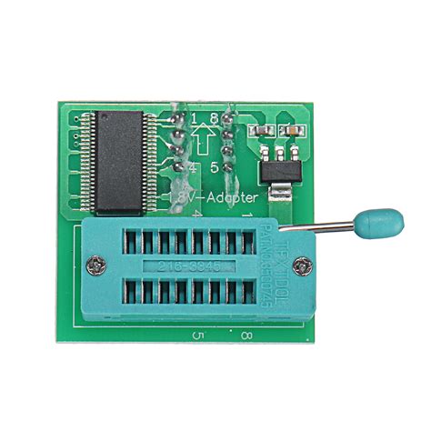
It does come with the 1.8V adapter but I am a little concerned as many reviewers mention the questionable build quality allows the voltage to swing up to 5V even when jumpered in “low voltage” operating mode.
I did order a Pomona blue, higher-quality clip (cost more than the entire CH341A kit from Amazon, lol) to improve my chances, but I was wondering if somebody might be able to let me know if I need to make any modifications to the cheap programmer PCB or any of the adapters to keep from frying any chips unintentionally.
My BIOS chip I plan to modify is a GigaDevice 1.8V chip.
I have a quality soldering iron and am not afraid to do some work / mods, but am a newbie and could use some guidance.
I am aware, I need to make sure the clip is connected properly before connecting anything to power so as not to short pins, etc.
In the meantime, I will continue to scour and read the forums all that I can.
All of my project’s info can be found here: h t t p s : / / w w w . win-raid . c o m /t8747f54-REQUEST-AMI-Aptio-V-BIOS-AcePC-GKV-Mini-PC-Unlock-ALL-Menus-amp-Options.html
I’ve got the black CH341a-programmer and a (lightblue) 1.8V-adaptor.
Tested it with a voltmeter. The voltages are reliable at both devices (programmer 3.3V and adaptor 1.8V).
Yes I tested mine with my multimeter while plugged into a USB power brick.
My results are below:

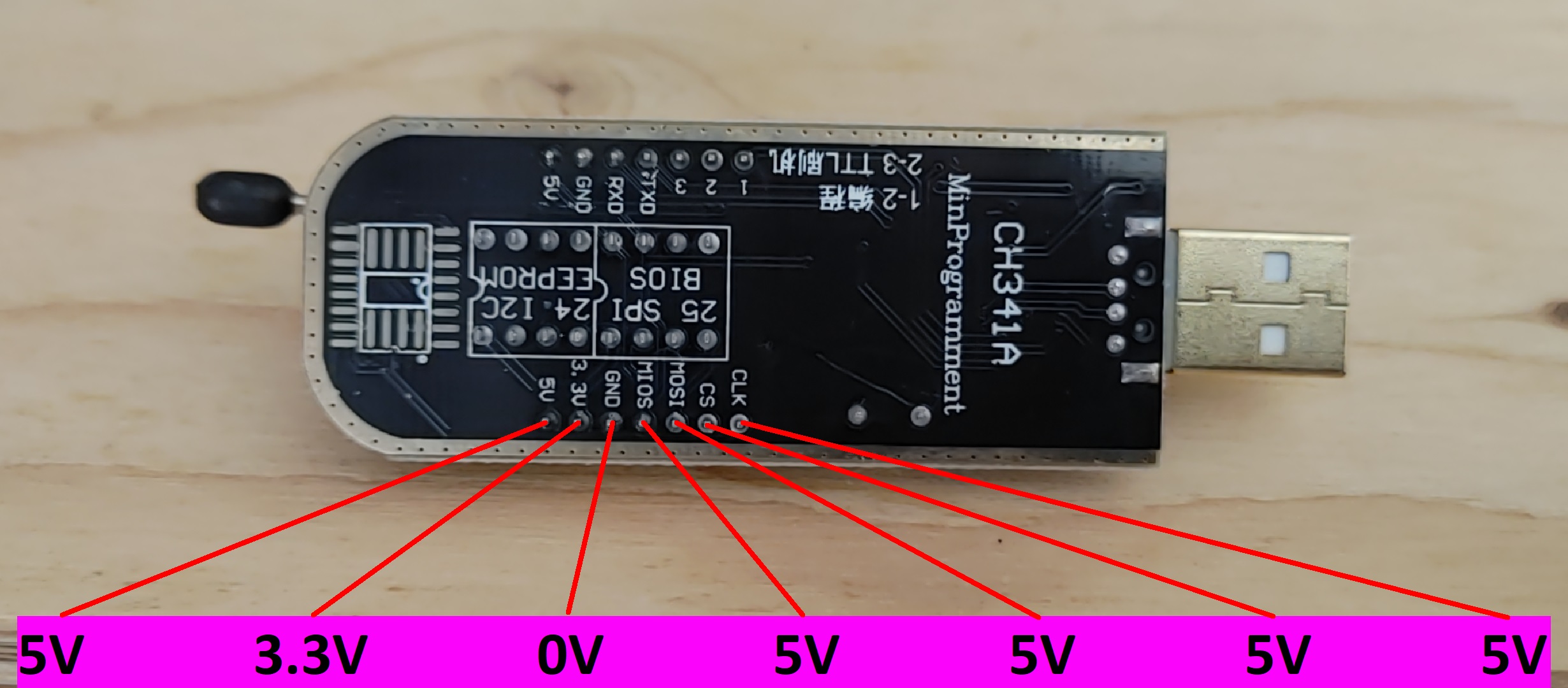
Are pins 2 and 4 on the 1.8V adapter supposed to be 0V?
What’s your opinion on this CH341A-based programmer to flash SPI EEPROM ?
It seems to have chip and programming voltage of 5v, 3.3v, 2.5v, 1.8v
I have ordered 3 of these today
English info > https://www.aliexpress.com/item/4001108200004.html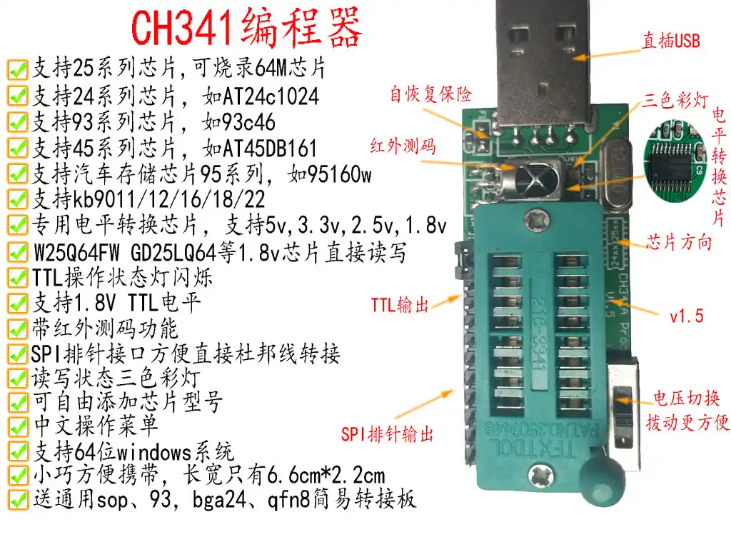
It’s OK, I’m using it.
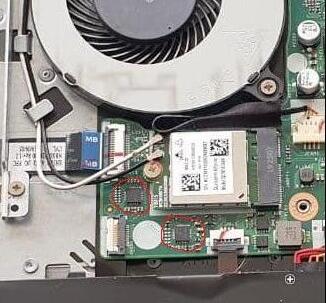
I’ll need help identifying the chip to program on my MSI B550 Unify-X motherboard.
I think it has a 32GB chip. Will that be a problem and should I cancel my order of the programmer?
Hello,
yes, it should be a 32MB (MegaByte), more exact: 32MiB (MebiByte), chip.
The BIOS file is 32MiB large.
That’s not a problem in generally.
You need to find a programmer tool, that can detect this (or similar) chip to write on it.
Please make a photo of the chip or read all the characters & numbers to discover it!
Best regards
I have an hp 15-bs076nr laptop with a corrupted bios (presumably), bios chip is W25Q64FVSIQ. Unfortunately the bios driver gives me 5 files. I’ve tried all five of them using W25Q64BV on neoprogrammer. Only 08328.bin does much, screen turns on with no image and fan spins. I made the stupid mistake of not reading the chip, assumed it would be a default option on neoprogrammer. The other ones either have do nothing or a bit of fan spin.
I do not have a 1.8v adapter, is it needed in my case where the programmer still ran without errors? It is a 1.8 bios (actually measures closer to 1.5 on the board).
25Q64FVSIQ - 2.7 to 3.6v, the 08328 and all others is for specific board model inside same line in the 15-bsxxxxx (Board LA-E791P…not sure).
That ID of ur system board was indeed in the SPI…u need visual identification in the board pcb
All do images seems that do not contain an Intel ME FW image
Beside the main image also needed the EC

It’s from the Tomahawk but should be the same chip as the Unify-X. I can’t get a decent picture of it on the board with my phone but the numbers are almost the same.
Edit: And it’s a MSI B550 board. I think I need a 1.8v adapter, right?
Yes, it’s a 1.8V 256Mbit (= 32MiB) chip from Macronix:
https://www.macronix.com/Lists/Datasheet…6Mb,%20v1.0.pdf
Newest UEFI/BIOS version (atm from 2021-06-21) available here:
https://www.msi.com/Motherboard/support/MEG-B550-UNIFY-X
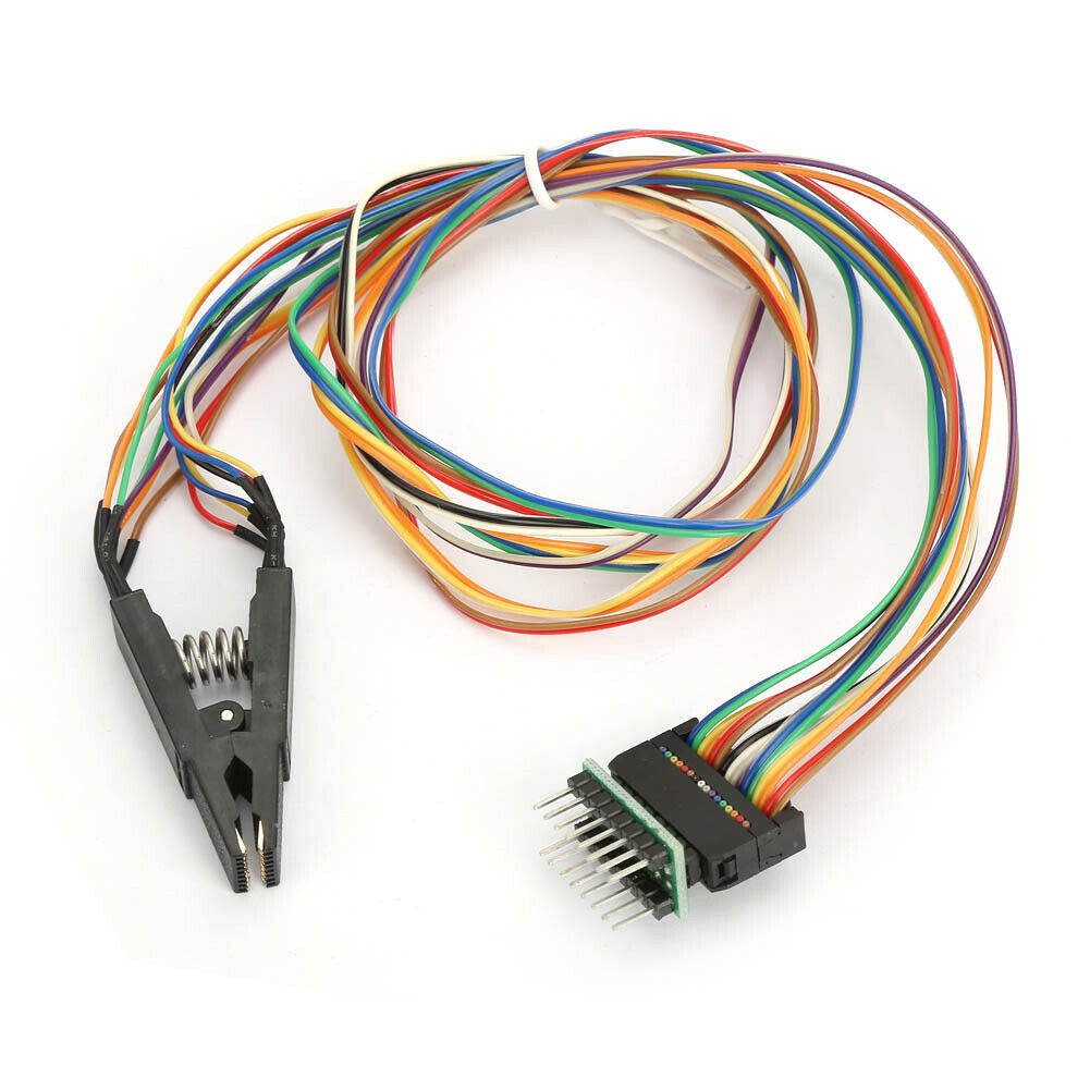
How exactly do I connect a standard CH341AUSB Programmer that has the separate 1.8v adapter?. I need to know how to connect the 1.8v adapter to the programmer and the SoC clip to the 1.8v adapter and then to the the BIOS chip .
This is the one I have.
https://www.aliexpress.com/item/10050018…577ae41ed071-23
google json checker
hello I would very much like to inject a new bios on my chip I have the ch431A my it does not find the chip you help me please?
chip winbond : w25q128jvsq or w25q128jvso I can’t see very well