So this is my first time modifying BIOS. I hope this is the correct place to post this.
I have MSI B85-G43 Gaming and I want to add NVMe support. Could someone check if the modified BIOS looks alright?
This is the original BIOS downloaded from here. It’s the newest version C.8.
And here is the modified one.
I used MMTool Aptio 4.50.0023 and just changed the extention to the original one since the tool could only save as .fd.
@daniiooo :
Welcome to the Win-RAID Forum!
Thanks for having uploaded the original and your modded BIOS.
Result of my inspection: The insertion of the NVMe module has been done perfectly.
Good luck for the BIOS flashing procedure and Happy New Year!
Regards
Dieter (alias Fernando)
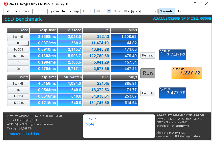
Joined the forum to thank everyone involved in making these BIOS mods possible. Everything worked with little or no complications, and I have managed to breath new life into a long-in-the-tooth system.
System details:
Motherboard: GA-990FXA-UD3 R5 (Original BIOS version: F2)
Processor: AMD FX-9590
OS: Windows 10 Pro 64 Bit
System Drive: ADATA SX8200 PRO 512GB
Graphics: Sapphire Radeon HD 6670
Anvil SSD Benchmark Scores:
Read: 3,749.93
Write: 3,477.79
Combined: 7,227.72
@731 :
Welcome to the Win-RAID Forum and thanks for your report.
Happy New Year!
Regards
Dieter (alias Fernando)
Firstable, Happy new year to All of Memebers on Win-RAID forum.
I’m new member.
@Fernando can you help me:
1. I’ve bought new M.2 Samsung 250GB 970 EVO Plus for my PC:
- Mainboard: Gigabyte GA H97-Gaming3 rev. 1.0, BIOS F7 (lastes BIOS).
- Intel i7 4790.
- RAM 16GB.
- I have VGA card: ASUS GTX760-DC2OC-2GD5.
2. with my M.2 Samsung 250GB 970 EVO Plus:
- I check in Samsung Magician Software, my SamSung EVO Plus has just ealized: PCIe Gen 2 x 2 .
- My Samsung 970 EVO Plus has format and boot with UEFI, it will use for Windows 10 installed - clean installed in my Samsung 970 EVO Plus.
==> So, can you help me to make my Samsung 970 EVO Plus work with full specification: PCIe Gen 3.0 x4, NVMe 1.3 .
Thanks for supporting me,
Philip.
Thanks for the amazing write-up and all the work done on this!
"A mainboard with an AMI Aptio UEFI BIOS"
How do we know if we have a motherboard with this type of UEFI BIOS?
Thanks!
Mike
@philipvn @dmikester1
Welcome to the Win-RAID Forum!
@philipvn : The BIOS F7 for your mainboard natively does fully support NVMe (I just checked it) and I am pretty sure, that there is an on-board PCIe slot, which offers PCIe3.0x4.
There is nothing I can do for you. Maybe you have to change the PCIe slot.
@dmikester1 : If you are able to open the specific BIOS by using an AMI Aptio UEFI MMTool, it is an AMI Aptio UEFI BIOS.
Good luck and a Happy New Year!
Dieter (alias Fernando)
Thanks @Fernando Can you show this PCIe Slot for me picture of mainboard that i’d attached !?
I have some information about mainboard GA H97-Gaming 3 has PCIe Gen2 x 2 : https://www.mydigitaldiscount.com/m.2-ng…y-list-p34.html
So, if it true, i’m so sad: my Samsung 970 EVO Plus has used PCIe Gen2 x 2 .
Thank you SO much for this extensive guide. I just got it working on my old Asus Maximus V Gene on BIOS 1903. The only issues I’ve noticed are I get random DXE driver error holding up POST on the first PCIe (red x16 3.0) slot coupled with half the speeds (??) of the final slot, CSM configuration errors in the second slot, (red x16 physical/ x8 electrical 3.0), and it works great in the final slot (black x4 2.0). Roughly 1.2-1.4 GB/s on the x4.
Note on my first slot: I’ve had lots of issues with GPUs, so I think that one is bad somehow. Haven’t been able to identify a cause yet.
@zshift
I hope I don’t give wrong tip. If the problematic PCIe slot, and its lanes came from CPU, maybe it’s the CPU (if the lanes on that slot, were really routed from the CPU.). If you’d have a spare CPU you could test if it’s not happening there.
Or but first check PCIe slot mechanical issue: At both sides of the PCIe slot at the top-side you see many small max ca. 0.5-1mm little rectangular holes in regular distances from another. In that holes are the PCIe-slot-pins going through (on the upper) side of the pins, which are elastic and (sprung-loaded). When no card is inserted, those metallic brass- or gold-plated pins normally show within the tiny hole in direction to the card-slot from within the hole’s side.
Sometimes when such pin is bent a bit, it is directed more to the outer side of such hole to the outside wall of the slot, allthough it shouldn’t as long no card is inserted pushing it a bit to the outside.
Because I had a similar potentially problem with two DDR3-RAM-DIMM slots (similar system way as with PCie-slot with those holes and pins). A few pins on two DIMM slots were a little bit bent (sideway) to the outside of the DIMM socket, allthough no DIMM inserted. This caused Memory problem, that pins not having contact to the DIMM’s pad when inswerted, causing RAM-modules in those DIMM slots not being detected.
The bent pins were only bent max about a half to 1 millimeter max. to the outside, but that was too much alredy.
I never had achieved to bent any pins ofa slot this way, that would cause issues, the board gotten used on ebay had had that issue already.
After I carefully bent those pins back (sideway) to inner Position of the hole-side (directed to the inner slot), it solved the issue.
Watching by, comparing with the other slot-pins helped, in which way they are regulary orientated.
Maybe if it’s not the CPU, your PCIe- slot has some pins are not in regular placement.
I’d assume, all PCIe- Lanes, that are in behind of first bent position of a further PCIe-lane and/or behind a twisted PCIe-GND-PIN, where a pin is not in proper alignment, would cause all PCIe- lanes in behind to be switched off.
And/or maybe it’s just the PCIe-M.2 adapter and not the slot.
If all PCIe-PIns pins in the inner slot and their positions tiny holes look quite/nearly regulary sitting as the other one in line, then nothing is bent, and all OK from the mechanic perspective.
When a card is inserted, the pins are pressed a bit from the inner wall of the hole sidewards, visible on the upper side from exit-hole. This is normal.
To test whether a pin is bent or not, the card has to be removed from the PCIe-slot of course, and then check that there is not any irregularity with any pins. Also take a flashlight, which helps, to check if the slot is OK. (You’ll see from the tiny exit-hole from above, (also) with a card installed, that an e.g. sidewar- bent pin is pushed more to the sideway to the outside than the others pins.
Be careful if bending pin/s back sideway a bit to inner position, that it still stays also on the upper side within the hole, be careful (the plastic seperation-protection-wall to the slot (on the top) doesn’t crack, because it’s is a bit thin and there could crumble off some small plasctic pieces (bot no drama as long pin is back in correctly aligned shape)
also take attention if trying to bend back anything accordingly, that within the inner slot, the middle+down-side of the pin stays in same postion being in line as the other good pins, and leaving an as far gap (ca 1.5 to 3mm) to the other pin’s side on other side of the slot (next to), as the other good pins do, and that they are rectangular turned , and in parallel like the other pins do, so if pushing a card in, the pin will not be bent flat to the floor of the slot (more seriously damaged).
This happened to me first when bending RAM-slot pin too much to inside, when after inserting card.
Interestingly this brass/gold plated pins can be bent more without breaking than I expected. I managed to bent this pin back without breaking (but this took me 2 hours), to manage to grab that fully flat plat pin from the floor carefuly with the needed small tools, back (up) into into proper position,RAM-slot after repairing working again perfectly. And really looks very nicely regular again as the other pins. ![]()
When inserting card slowly, watch that the repaired pin doesn’t move into the slot (you’ll see that they could happen, when card is pushed in a bit, and the upper side of the pin leaving the hole going entirely into the inner slot.
Furthermore sometimes the pin is "just" bent to the bottom (still being mainly within the hole), and the light won’t reflect and it appears the pin was missing , even though it’s not. This can be checked when removing the card, if at least the middle- and down-side of the pin is still visible in the slot or not. A bent pin to the downside could be risk, that at next insertion of card it could be bent entiely to the the floor, so be careful also that it is stretchted in shape, and (bordering) at the top-exit-side of the upper exit-hole, like the other good pins.
I’d recommend using two tiny clocksmith-tools, one (or thin EC/banc-card or (smaller/thin) flat screwdriver)in the inner slot fixing the pin holding it/not going too much inside, and the one clocksmith-tool to put carefully hole on top side (next to the pin), bending the pin careful the the inner side of the hole. Careful too use really tiny clocksmit-tool so that putting it in rectcangular hole above, that it will not hit/push nor bent the pin to the bottom, but that the tool is teny enough to go next to pin inside the hole.
Usually on the down-side the pin is not bent very much at all to the outside, it’s rather the upper side-area of the pin.
–
Yep, I normally take "FPT", when firmware is newest version already (updated via different and by others more reommended tools), then to make backup-dump with "FPT" of this, modifying that dump with newest microcodes etc, and then flashing dumps or modified dumps only back with "Intel FPT" .
In this case, there was the issue with the MSI ZH77A-G43 Mainboard that it didn’t boot, to be able to upgrade the firmware via the MSI MFlash utility/Afudos etc. (And the backup BIOS still has that memory compatibilty issues).
In rare cases where it booted at first, I backuped firmware via MFlash utity, but it dumps only 6144 KiBytes, which I didn’t notice at first.
The mainboard had seemed to run normal, I played with the firmware options a bit, looking through the menu.
After applying some firmware-settings (and generally when rebooting) it hadn’t wanted to post any longer, CMOS-reset, trying all DIMM slots and different RAM, reseating CPU had not helped etc (and CPU just tested working in other mobo).
Most of the tries to get it booting, when it functioned I tried to (upgrade) the newest firmware with MSI internal MFlash utility, while I could.
But the firmware suddenly had crashed before the MFlash process could be started etc.
I also had tried to use FPT to backup whole chip, when I noticed that the MFlash backup image was only 6144KiBytes of 8192 KiBytes.
But for this it had been too late (gernerally no longer wanting to boot - quite later at beginning it showed those signs).
So in the end only option was to use external programmer.
, to backup whole firmware via ICSP, and flashing the newest stock BIOS (in this case), via ICSP, which should have the memory compatibility and posting-issue resolved. This proved out to be right ![]()
The special trick I mentioned (mentioned in that direction on "flashrom" internet site ("ISP"), to be able to program via ICSP/(ISP), that was also tested before on an Intel S1200BTS.
—
Now with the newest version, that board at least works fine
The MAC address of the adapter is still shown, and Windows 10 gets activated when installed. Maybe missing serial number, (but flashing a newer firmware (newest stock BIOS version) with the serious memory-compatibilty errors corrected, was the only option in this case).
—
@Lost_N_BIOS
I’ve watched a bit strange phenomenom (see below), and showed in screenshot. Would you have an idea? (see below)
I had dumped original firmware with external programmer before flasing newest stock firmware.
(FPT to dump it, was no option as board had been no longer posting).
While I dumped original firmware with external programmer via ISCP, I did it 35 times to check how reliable the process was, and if the read data was correct:
Reaing whole EEEPROM’s content takes about 20-30 seconds max with TL866II Plus programmer:
In ca. three minutes to read whole EEPROM chip four times, I get always this same checksum, in several read-outs in this period: (sha256sum)
124f08e01c4ad12ad7da1292a1224110552ed7b38c4bdccf4cfe5d8624eca0cb
Then at next ca. 3 mintes period, from several re-dumping firmware with programmer. I always get this checksum in several read-outs in this period:
50c65dd792ee095c77336dee663793a4e5d6e6dbdefc12fd7fc83abd6d469da6
See screenshot, (especially right black PuTTY-window) with the sha256sum checksums from the dumps I made:
=> file.php?url=http%3A%2F%2Ffiles.homepagemodules.de%2Fb602300%2Ff50t871p100415n6_lINyewEL.png&r=1&content=RE%3A_Gigabyte_GA-Z77X-UDH5_Successfully_boots_to_Win_10_from_M.2
Then in the next 3 minutes I get again this first one back, in several read-outs in this period: (sha256sum)
124f08e01c4ad12ad7da1292a1224110552ed7b38c4bdccf4cfe5d8624eca0cb
Then next 3 minutes the 2nd checksum back, in several read-outs in that period: (sha256sum)
50c65dd792ee095c77336dee663793a4e5d6e6dbdefc12fd7fc83abd6d469da6
And so on.
Do you have an idea, what could be causing this?
It principially reads out identical data, and gets the Chip-ID correctly, with and even without ICSP-VCC enabled.
Those two periods with two different checksum results, are alternating each other within ca 3 minutes, and always among themselves repeating to read (identical) data.
(I’m 100% sure that I also always cleared the Programmer’s- software’s buffer, for the next read-out, I double checked that, and anyway it’s set in the software to do it automatically)
Do I have a valid backup dump? Are those both checksummed backups valid, or only one of them?
See two zip-attachments below, of the two checksum patterns repeating.
A few (first) checksums are not identcial, but here I had used the ZIF-Socket-ICSP clamp, which provided less mA max current, and afaik, and where I hadn’t set the board in some kind of mod yete, (where it couln’t get the CHIP-ID permanently.).
Later attempts which appear to be good, are in the stable CHip-ID-mode,
I metioned few post ealier with some kind of trick (to prevent the boot-loop etc from happening), CPU+RAM+GPU+PSU installed.
(And board had to be powered, of course for the programmer to do its job)
And programming newest stock firmware and succefully verifying written data (same checksum), also to the original file, when verifying, so the ICSP connection was being OK, correct?
(And in the screenshot you should see, even with ICSP-VCC disabled, and in Xgecu software Checkbox "Check-Chip-ID" was checked, still get’s chip ID (in this case).
while "successfuly message" and the hex code result shown in background.),
and in the right black window (see file names from several attemps epxlicitely marked where the ICSP VCC was diabled)., also identical checksum alternating periods, with ICSP enabled and disabled.
–
2nd question/proposal
Mattering probably lost serial number:
While this board is working perfect now with 0x1.A firmware version, what about reflashing the original 1.4 (8192 KiBytes) dumped version from programmer, with "FPT" in FreeDOS? But I wouldn’t reboot, (as then the board won’t post again, due to BIOS memory compatibility bug in that version).
Then after flashing 1.4 backup dump, staying in FreeDOS opened, and then flashing right away newest original stock 0x1.A (1.10) version with "FPT" back, but with "SAVEMAC" switch:
fpt.exe -F E7758IMS.1A0 -SAVEMAC
Is this good? I didn’t find another parameter about transferring over any serial number in "FPT". Anyway for this board the MAC-adress doesn’t appear to be stored in the EEPROM and/or stored elsewhere (is still listed with a (fixed) same MAC-address in the firmware’s -hardware-information-rubrick", also after stock-BIOS-FPT-flashing, (in this case) with some numbers, neither being FF-FF-FF… nor 00-00-00… .
(Or just taking Afudos while the system stays running in FreeDOS, to reupgrade to 1.10) ?
(The uncertainty remains with those two alternating repeating checksums from backup attempts, if any or both backups were valid,
which one to temporarily flash back, from which one of those two 1.4 dumps to reupdgrade to 1.10, with "FPT" with the savemac-option, (or maybe better with Afudos.)
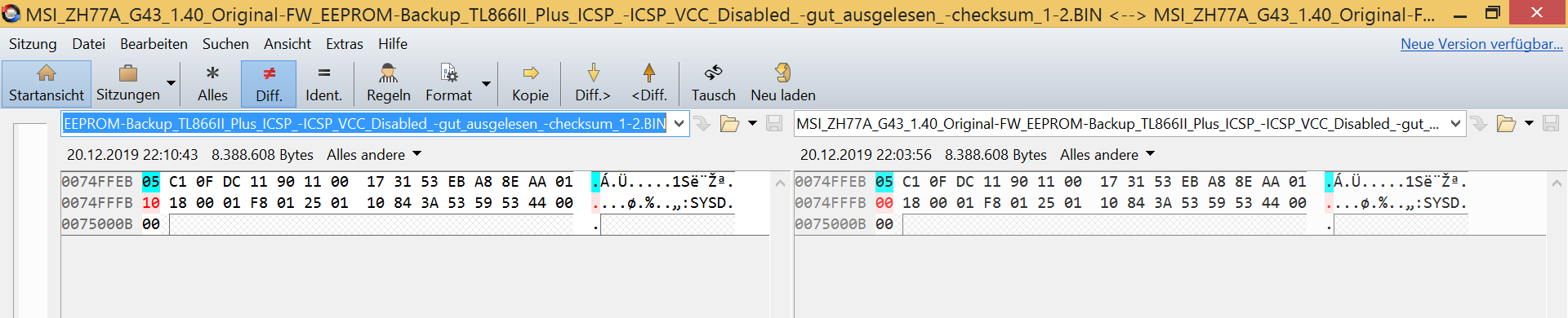
[Edit] never mind. The difference in those two repeating two alternating checksum periods, is only 1 Byte (at offset 0x74FFFB), maybe Flash descriptor toggling, or whatever…
–
Besides happy new year. 
have the Asus Z87-WS modded for NVME boot - paired with an Amazon card and WD 1 TB black drive and it just screams fast! A HUGE noticeable difference. Thanks to the OP for posting the instructions and providing the driver. I ordered two more setups for servers as i now feel very comfortable in getting this to work ![]()
If ANYONE needs a copy of this BIOS, I will share it on mediashare
Thanks
Tim
@Vincent12 - if all of those 35 dumps do not match in hex editor, then no, some or all of them may be invalid. All dumps should hex match and have exact same checksum, especially that close together and without you trying to start the board between dumps etc.
I don’t know anything about flashrom, or the programmer you mentioned, so I can’t advise on any of that wall of text other than what I wrote above
Serial number can be put back into BIOS later once you are running again, if you ever find a valid way to write BIOS (sounds like it’s failing now, which I expected since your dumps are not matching either)
FPT -SaveMAC only works in certain instances, if MAC is kept in certain region, and if you are overwriting that region (GbE). Not all boards use this, and further not all boards that have that region always store MAC ID there solely.
Does your Ethernet work? If yes, then possibly MAC ID is stored direct in LAN chip FW. If ethernet does not work, find LAN MAC ID on sticker on board, give me a single dump of your BIOS that you know is good, and I will fix it for you.
On your compare image, no, that can’t be any “FD” toggle, FD is at first 1000h of the BIOS, that looks to be near the end of the BIOS (if 8MB), hard to know though since 8MB BIOS should end at 007FFFFFh (and what you show, if end of file, is only 7.xMB)
So that is probably invalid AND incomplete BIOS dump
Final thought >> DO NOT use AFU to flash BIOS at all here, it will only cause you future BIOS issues. Use FPT, or MSI’s built in flash utility (M-Flash)
@philipvn as Fernando mentioned, this board has PCIE 3.0 slot, but only the main x16 one is 3.0. The x16 (x4 electrical) slot is only 2.0 per the spec page - https://www.gigabyte.com/Motherboard/GA-…-3-rev-10/sp#sp
If you are not a gamer, and don’t care about having PCIE 3.0 @ x16 for graphics, you can move your graphics card to bottom PCIE slot (x16 @ electrical x4 @ PCIE 2.0) and put NVME in the first x16 slot which is only 3.0 and only x16 slot
Or, you can leave the NVME in the x16 (actual x4 slot) and run it at x4 2.0 << If you do that, be sure to set x4 at the BIOS peripherals page as outlined in spoiler below
1 x PCI Express x16 slot, running at x16 (PCIEX16) - (The PCIEX16 slot conforms to PCI Express 3.0 standard.)
* For optimum performance, if only one PCI Express graphics card is to be installed, be sure to install it in the PCIEX16 slot.
1 x PCI Express x16 slot, running at x4 (PCIEX4)
* The PCIEX4 slot shares bandwidth with the PCI Express x1 slots. The PCI Express x1 slots will become unavailable when a PCIe x4 expansion card is installed.
* When installing a x8 or above card in the PCIEX4 slot, make sure to set PCIE Slot Configuration (PCH) in BIOS Setup to x4. (Refer to Chapter 2, “BIOS Setup,” “Peripherals,” for more information.)
2 x PCI Express x1 slots
(The PCIEX4 and the PCI Express x1 slots conform to PCI Express 2.0 standard.)
@ BIOS Peripherals section -
Initial Display Output - Species the first initiation of the monitor display from the installed PCI graphics card, PCI Express graphics card or the onboard graphics.
PCIe 1 Slot Sets the graphics card on the PCIEX16 slot as the first display. (Default)
PCIe 2 Slot Sets the graphics card on the PCIEX4 slot as the first display. << Set this, IF you move graphics card as I mentioned
PCIE Slot Configuration (PCH) - Specifies the operating bandwidth for the PCIEX4 slot.
Auto - Lets the BIOS automatically configure this setting depending on the expansion card being installed. (Default)
x1 PCIEX4 operates at x1 mode.
x4 PCIEX4 operates at x4 mode. << Set this, no matter what
@zshift [Edit]
You can even run e.g. a PCIe-x16 graphics card in a shorter PCIe-x1 Slot and in a short PCIe-x4 slot, see picture here.
But the PCIe-slot has to be open on the back-side, see picture here:
https://upload.wikimedia.org/wikipedia/c…rd_IMG_1820.JPG
My Mobos, don’t have open PCIe-x1 Slot. I’ve used some kind of "Dremel"Tool, with a 1-2mm-diameter driller, and putting a ca 2-3mm thick plastic piece (from e.g. an old HDD-case) into the PCIe-x1 slot (as long as the slot to the backside), to prevent the driller from inserting the PCIe-x1 slot.
And then drilling through (sideway) from the the outer-backside inner-slot-wide ca 3mm long piece off. Worked perfectly with the protection-piece inside the slot.
Done that with 10 mobos on all x1-Slots and some x4-Slots. Had a bit bad luck with one Mobo’s PCIe-x1-slot , but nothing broke, luckily only just reacted turning off drill-machine quickly, it still was possible to bend all few damaged PCIe-x1 pins nicely regulary back into position 
—
@Lost_N_BIOS
The two dump images are a full of exact 8 MiBytes (8192 KiBytes or 8,388,608 Bytes) of course.
[Edit] I had to power mainboard, otherwise too much power draw from the Vcc pins, and flashrom-site even recommends/propose also to power the board, when it’s not working without powering it. (The programmer also has short-circuit-protection, and watched that SOIC-clip is attached properly.
https://flashrom.org/ISP
(I tried their tips, but using XGecu/MiniPro programmer software for Windows, and/or Linux Github/Utils for MiniPro/Tl866X by DavidGriffith)
----
The screenshot from Beyond-Compare of those two images is just showing only a snipplet of the full image(!),
as in the Beyond-Compare-window in the screenshot is selected to show only difference/s in file.
+Not to be confused, in the screenshot the left offsets are displayed a bit shifted.
(I haven’t found yet a setting in the Beyond-Compare-program, also when displaying file differences, that the most left slot for first offset of a line (the last 1-er-digit) begins with a “0” and not e.g. with a “B” at this example (or 1 , 5 , or C etc) depending on position of file difference)
To be clear, the programmer reads within 3 minutes, when several reading-out the EEPROM, always checksum 1.
Then in the next 3 minutes, after several dumping, it reads (always) checksum 2.
Then in the next 3 mintes it’s always dumps checksum 1 again (several attempts!)
Then in the next 3 minutes, after several dumping, it reads (always) checksum 2 again (several attempts).
There’s only 1 Byte difference between the two images.
Read firmware shows also CPU-microcode.
And seeing both images in hex editor it shows data, and a few smaller gaps with “00” and "FF"
Furthermore it get’s the Chip-ID with “ICSP VCC enabled” and with “ICSP VCC disabled” for this board,
and it shows with those both settings exact same resulting behaviour.
Furthermore when programming chip, (e.g. had to use stock BIOS in my case), after programming Chip, written data was identical to source file(!) ![]()
Furthermore, several mainboards in the past, it seems mainboard writes s.th to EEPROM after a reboot.
Tested out by reading out (swappable) EEPROM chip in the programmer (without in-circuit) before computer turning on.
Then putting EEPROM back, starting computer newly, turning computer off. Putting EEPROM back into programmer.
Result different checksum. Really odd. But here the reesult were only randomly (more and more different checksum patterns (in between rebooting PC with EEPROM in), when redumping EEPROM.)
Same result, when using “BIOS Backup Toolkit”, instead of using programmer, same result…
Several mainboards (e.g. Asrock P45DE3 Socket 775 without ME-firmware) in the past, it seems mainboard writes s.th to EEPROM after a reboot, allthough expected only to store mainboard settings in CMOS.
On one another computer (Wortmann-Laptop), there wasn’t that strange thing.
—
@Lost_N_BIOS
So the images I propose are still faulty? Why that phenomenom happening?
If the programmer couldn’t read reliably the images at all, how can it get principially same checksums?
Normally with those issues (via in-circuit), always when dumping it should have randomly more and more different checksums, the more dumping it again, but here that is (NOT) happening.
And had watched in the past, (on other Mobo-hardware), the ICSP connection was “meta-stable”, but needed “ICSP VCC enabled”, and sometimes it got randomly different data, and after a few attempts it got identical checksum.
Here it’s really only one Byte in difference, happneing at exact same position between the two 3-min-periods,
where within it reads alyways checksum 1, and at the next period always checksum 2,
and so only those two alternating checksum-1-period and checksum-2-period happening, nothing else.
Yes, I had the past where it reads identcial checksum always, but there the hex data inside was entirelly/mainly “00” or “FF”.
Haven’t found yet a good plaubsible explanation for this phenomenom behind it, other than that the “chip was soldered, would need to desolder it” (NOT for this kind of case)
And yes it read’s also chip-ID steadily, after put the board in some kind of mode.
Is this caused by ME-firmware?
I’ve have to remind, programming chip, and redumping EEPROM after programmed, yes, identical checksum. And did that programming EEPROM on ZH77A-G43 via ICSP two times, yes result still has exact matching hash, as the source-file.
@Vincent12 @zshift
Since your specific problems have not much to do with the topic of this thread, whose volume is already very big, I propose to move your detailed discussions into separate threads.
Please tell me, which topic title you would prefer for your specific problem.
Yes, maybe good idea.
Hm, what about “Delock [model name] PCIe M.2-adapter & ADATA SX8200”?
But I’d need to wait for pako what he’d say/propose.
About my In-circuit-tests/proposals experiences and long text, it’s no issue to me to move into other or new thread:
Maybe there’s a suitable thread about ICSP already to move into, and about dumping firmware with programmer.
[Edit]
e.g. moving to here: [Guide] Using CH341A-based programmer to flash SPI EEPROM (32)
Or as a new thread "Guide Using TL866II Plus programmer to dump and flash SPI EEPROM via in-circuit - experiences"
And thanks for patience.
Hi and first of all… thanks for this detailed post to help people out this way! Much appreciated!
I would like to ask a question regarding the flashing of the bios once the edits are made on the new rom file.
I followed the guide and editted the flash file (UEFITool saves it as a .rom file, i renamed it back to xxxx.430 as the bios file is originally named (maybe here is where it goes wrong?)
Rebooted and went into BIOS to flash the BIOS with the editted file loading it up from a usb drive.
Computer finishes the flash without any problems, reboots, but then nothing changed.
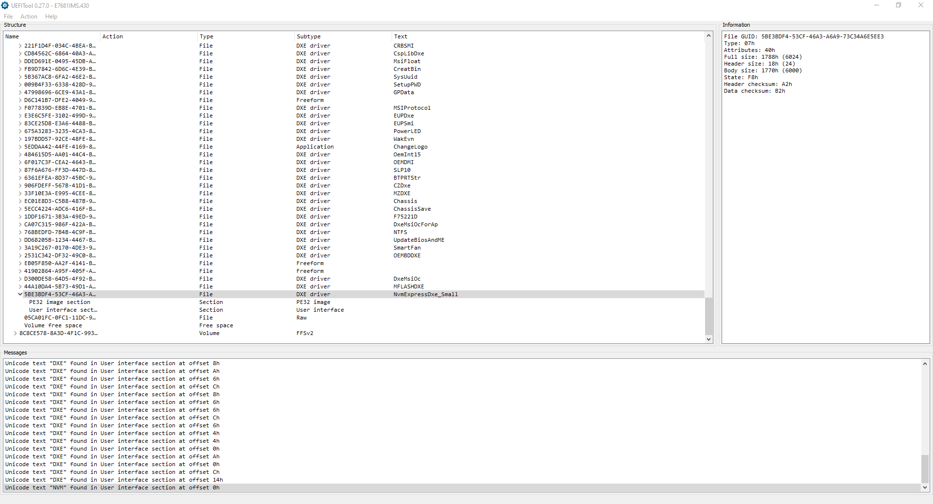
When i load into the BIOS and save the current (flashed) BIOS file and open it up in the UEFITool it isnt containing any injected file (NvmExpressDxe_Small) anymore.
Am i missing something?
The board is: P67-GD65, using the v4.3 bios file to flash it.
@Vincent12 - Sorry, your posts are WAY too long to follow, I thought I wrote too much myself, but  Sorry That’s way too much info, speculation, statements, questions, thoughts etc,. for me to follow along.
Dump only needs done once if it’s beiong dumped out correctly, but as I mentioned, if you are not powering on this system between dumps (at all, ever) then 1000000 dumps should all match, if not there is a problem with how you are dumping and there is no way to know which is proper dump.
Even if 9999999 of them match and 1 does not, there is know way to know which of those is proper. The only thing to do in such a situation is to dump differently, that could be different programmer, different software version etc.
Also, as I mentioned previously, if you are powering on, or attempting to boot this system, even if it’s bricked, then dumps between power on attempts are not going to match (ie stop doing that, it’s pointless, no need to compare like that etc)
If you want your board fixed (ie BIOS recovery), as Fernando mentioned, please make your own thread, with the brand and model of the board in the title. Same I guess if you simply need a NVME Mod BIOS and the board is currently working fine.
Then provide a link to your stock BIOS download from the manufacturer, and provide me with the first BIOS dump you think is OK (one file only) If the board is working though, and it’s an Intel CPU board, I’ll probably have you dump BIOS region via FPT and we’ll do it that way if you just need NVME
The thought of you using programmer sounds very confusing with your previous post style, so hopefully we can just do FPT 
@DiviNe187 - You’ve lost padding file at edit, so hopefully it’s not flashing anyway (ie may brick your board, quit trying)
I tested, for this BIOS you must use MMTool 4.50.0.23 to do the insert, or you loose that padding every time no matter which version UEFITool you use (it can be done with UEFITool, but takes a lot of extra effort, just use MMTool 4.50.0.23 instead )
Also, you do not need to use the “Small” NVME module for this BIOS, no matter how you did it
Once done, yes, rename to stock BIOS name, then flash with M-Flash from within the BIOS
Hello, thank you for guide, spent all night but it work.
MSA z77a-G43 (MS-7758) Motherboard
i use AMI’s MMTool 4.50.0023
-a) take USB and formatted it in FAT32 and
a) made recover i M-Flash in MSI UEF IBIOS here it https://drive.google.com/open?id=1gLKr3o…YwkgD9aT_va8h1o
b) open it in AMI’s MMTool 4.50.0023
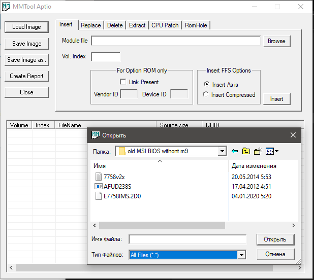
and rest was according a) Guide for the usage of AMI’s MMTool 4.50.0023:
and save it
c) take USB FAT32 with old file and copy new and MOST IMPORTANT, just delete one file E7758IMS.2D0 but new was E7758IMS.fd https://drive.google.com/open?id=1iuH_j0…WL3HJJbyOP3ubcT im just delete old and new just REMAME it from E7758IMS.fd to E7758IMS.2D0
d) go BIOS UEFI again im M-FLASH option
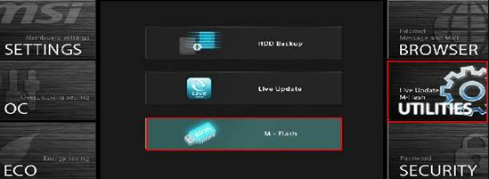
and choose something like updade bios of flash BIOS, use new, remaned E7758IMS.fd
e) prepare and inslall WIN10
z) result
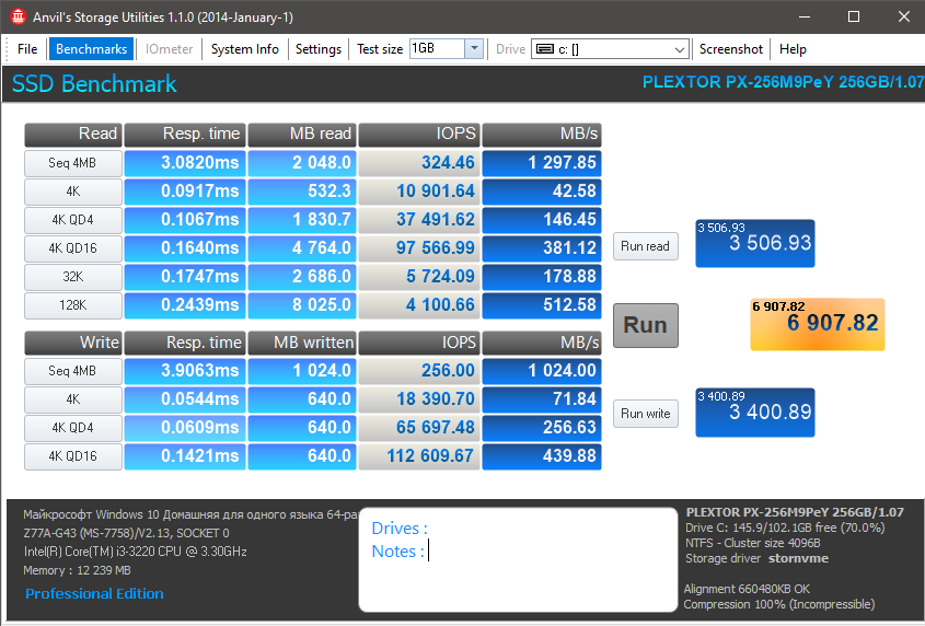
is it ok or in need make something to boost it ?
@Lost_N_BIOS
Thanks for helping
I’ve created new thread, hopefully it’s shorter/short enough. Mainly the marked-fat-lettered text further below is important only,
above is some background (but shorted), to answer some thoughts, that might come into place to you.
BIOS recovery (restore original serial numbers) but on latest (bug fixed) BIOS - MSI ZH77A-G43