First sorry for my poor english. I got one HPE ProLiant DL60 Gen9 1U Server.A C610 chips mainboard. I just want to remove the microcode to unlock the hasswell max turbo. I download the bios from HPE webside and remove the microcoude .But can’t flash it back anyway(like bios menu,hpusbtool(FWUPDATE),fpttool)… Then use uefi tool to find the setting file it just have (GPIO Lockdown,RTC Lock,BIOS Lock,Gbe Flash Lock-Down),I use ru.efi close them but still even can’t backup the flash. So…I check the SPI chip is a winboard 25Q128VSG 128M chip,but the bios file just 8M.May be for the me?This mainboard have a backup bios can change in the bios menu.HP iLO manage chip have same SPI chip too. In the attache file it has the download biosfile(U15_0325.19),IFR FIles,fpterrormessage,sceinfo. what should i do…
by the way,the board have 3 pci-e 16x sockets and 2 pci-e 8x sockets,but just 2 pci-e 16x is useful,so is that possible to unlock them with the bios… My spi programer is on the way…
Here is some update. On board is have 3 SPI chips… 1.The Intel UEFI IMAGE header and me roms—8MB. 2.The UEFI BIOS REGION IS ON OTHER 16MB chip.Another 8M is for bios region backup. 3.The HP iLO4 rom.Don‘t need it…
I change the Intel UEFI IMAGE Header unlock the fpt tool.The header also show ‘Number of flash Components’ is 2. But the AMIBCP5.02.0023 still can’t open the bios with 'Platform Identification failed.'
So i remove the microcode.But it boot with ‘275-Unsupported Procerssor Detected’ error and need update the ROM and don’t boot… I think is no microcode loaded the POST don’t allow to boot.
SO. 1.How to remove the microcode check… 2.How to change The PCI-E Config…
@carson512 - - “BIOS Backup” is maybe not that, but rather partial copy used in combination with hidden reserves to auto-reprogram any changes made unofficially by way of HP Sure Start However, without seeing the dump from each chip 1-2 I can’t say for sure what is what, but with Surestart it doesn’t matter. This is evil invention, and even with programmer you cannot beat, we’ve tried. We can do simple test and you can find out if BIOS region is Sure Start protected, by making simple change to a setting or update a microcode etc. I suspect it is, and even if you program in same BIOS region to main BIOS area, and backup too, it’s auto recovered to stock on reboot. Been there, done that, tried to beat this good but no luck.
Removing microcode has nothing to do with AMIBCP being able to open the file. So, are you saying you flashed in a mod BIOS on this system, and it did not auto recover on boot? If yes, then great, maybe we can mod your BIOS! 1. Not all systems can boot without microcode, but maybe you did this edit incorrectly, hard to say for sure. I will make you BIOS for this, if above is true (you can flash mod BIOS, and it’s not auto recovered with stock BIOS) 2. What do you want to do with PCIE?? Anyway, if it’s possible to mod BIOS here, I will unlock the BIOS Menu for you, so then you can set whatever you want for each PCIE slot.
I need programmer dump from all 3 chips, once you have, please put in single zip and upload for me. Before you do that, please reflash stock BIOS using stock method, that way it’s all stock BIOS and there is no failed edits in there.
Also, before you dump any chip, please confirm what each chip ID is ecactly, so I can tell you what software/version will be best for each, that way dump is good and you can write back without error W25Q128VSG is not correct ID, please look again and confirm is it 25Q128JV or 25Q128BV or 25Q128FV - If it 25Q128BV you need 1.8v adapter For all, look directly on the chip, do not rely on software to tell you ID because it’s not always correct.
Please also link me to the stock BIOS download page for the BIOS version you are using.
I assume there is FD/FDO/Service/Management jumper on this board, put a jumper on there and then you should be able to do whatever you want with FPT Be careful, make backups of everything first you can brick your system in one click with FPT!
Thanks for your help. The fpt way just can backup the ME file(8M). I use the iLO4 exploits to dump and write the iLO4 dump(16M) and the SYSTEM dump(16M).(https://github.com/airbus-seclab/ilo4_toolbox).I check it with the SPI Programer file it’s the same. And use SPI Programer to dump and write ME file(8M).Then change the header to FF make FPT can read the ME file
I try to update the microcode to the lastest with v2.30 bios.The system boot normaly and not recovery the microcode change…Maybe I set the maintenance sw1 to off the iLO security? Also i slove the pci-e problem with the RUtool Manual to change the IIO and IOU in UEFI setting.Looks like HP change the IntelRCSetup to “Platform”“Main” couse the AMIBCP can’t open it.Also the Setup is gone… If you can unlock the menu…It’s the bbtter way than the ru tools.Maybe also unlock the TDP lock? I want to remove the microcode just want to lock the cpu on the max turbo…
The zip file with this files which the firest backup : ME-25Q64FVSIG-8M.bin—Maybe the Intel UEFI header. ILO4-25Q128FVSG.bin—The HP iLO4 chip rom.Maybe the arm code. SYSTEM-25Q128FVSG.bin----Maybe the Intel UEFI BIOS region.It have two version of bios split it whith keyword ‘Compaq’. 1.v2.30 2016.09.12 download link here but can’t download without contract…https://support.hpe.com/hpsc/swd/public/…144e68377c27784 2.v2.72 2019.03.25 https://support.hpe.com/hpsc/swd/public/…749b79cc10d0844 this version can download with the account the download bios have a rsa sign…
about the jumper the img for the mainboard. 1.J12 J85 is the TTL socket but J85 show nothing… 2.J93 one 3.3V and one GND…Nothing… 3.J6 with two 3.3V pin and one GND.I try jumper it the pc can’t power… 4.J59 which near J6…system show a notice need update the firmware…
With the text above "Early system initialization, please wait…" IN ''GUID pattern "D7C10F34-D9F3-45D5-8D71-E8881E2A910C" with name ‘GromitInitPeim’ ‘’ I try to remove it with the blackscreen.
"Unsupported Processor Detected" IN ''GUID pattern "AAE07B90-4CF8-5986-AD2A-48B72CAB98A8" with name ‘HpSecPhaseErrorReportingPei’ ‘’ I try to remove it with the error below.
I use IDA edit the ‘HpSecPhaseErrorReportingPei’ to jump the unsupport cpu error… Than is show error same with remove ‘HpSecPhaseErrorReportingPei’. Then edit the ''PiSmmCpuDxeSmm" with another error like below.
@carson512 - I am on limited internet, please upload for me ONLY these dumped chips (ME-25Q64FVSIG-8M.bin–ILO4-25Q128FVSG.bin—SYSTEM-25Q128FVSG.bin) I assume you can write back whatever changes I make with programmer, so let me see all three chips dumped and I can tell you exactly what is what. I will look at menu and see if I can make IntelRCSetup options visible to you or not, generally if it’s outside of setup then I cannot, but rare instances it’s already linked and hidden, so I’ll have to look and see. * Also, please upload this zip to tinyupload.com or uploadfiles.io - I can’t download from Microcosft 99% of the time, and split attached files here is a huge mess - thanks
@carson512 - Yes, this is FD + ME FW regino >> ME-25Q64FVSIG-8M SYSTEM-25Q128FVSG.bin << This is BIOS region as you mentioned. It’s also a dual image BIOS region, either for two systems, or for single model but configured differently for some variants etc Have you edited this at all? FIT Table is broken. lots of errors too, but those could be normal I’d have to see stock BIOS to be sure. How did you dump that? Some of the errors could also be corrupted from dump if via programmer and incompatible software used. For W25Q128FV, CH341A software 1.18 can read properly but not write, aside from that I think only Colibri or ASProgrammer can read/write properly (At least from what I see confirmed here) Do you have a copy of stock BIOS? If yes, please upload for me to check, thanks. Also, please zip up for me an image of the BIOS so I can see all visible to you sections across top of however it’s shown to you (so I can see main, advanced, boot, exit etc, which are visible.)
This is “Insyde” BIOS, that is why AMIBCP can’t open it
TDP is only mentioned once in BIOS settings >> Config TDP Level, VarStoreInfo (VarOffset/VarName): 0x12F3, VarStore: 0x1, QuestionId: 0xBBF, Size: 1, Min: 0x0, Max 0x2, Step: 0x0 {05 91 B4 15 B5 15 BF 0B 01 00 F3 12 10 10 00 02 00} One Of Option: Nominal, Value (8 bit): 0x0 (default) {09 07 B6 15 30 00 00} One Of Option: Level 1, Value (8 bit): 0x1 {09 07 B7 15 00 00 01} One Of Option: Level 2, Value (8 bit): 0x2 {09 07 B8 15 00 00 02}
If you can see this submenu inside Advanced >> Advanced Power Management Configuration << Then I can make above TDP setting visible to you in BIOS without issue I can also make this submenu visible in there too, if you can’t see it now >> OverClocking Feature
Have you generated an IFR readout from the two platform modules? If yes, after looking around in there, what do you need visible in there that you can’t see now? If you’ve not done this, let me know, I will send you the IFR’s and you can look and see all the possible settings, then let me know what you need visible. I think you did this already, since you mentioned changing variables via RU. So yeah, let me know what you need visible
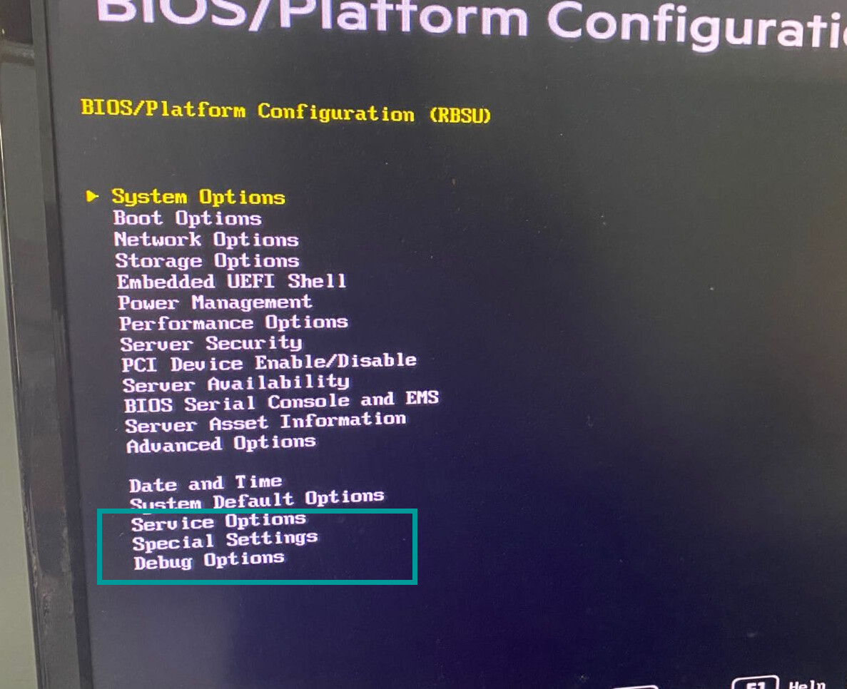
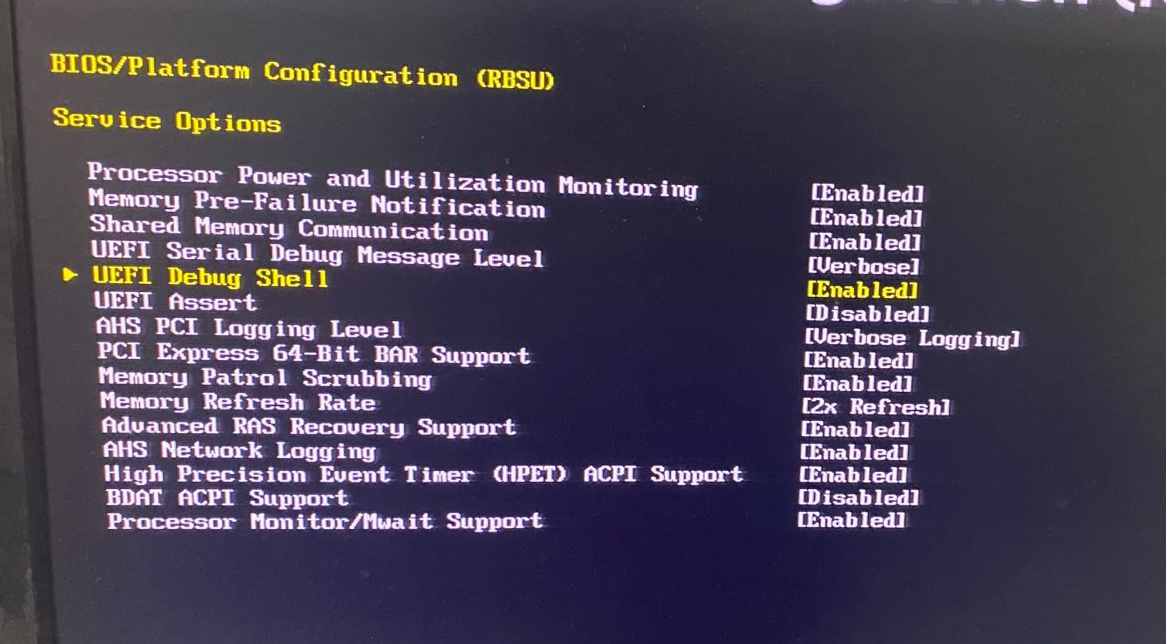
All the roms was backup form the Original state without edited. and double check with programmer readout files they are the same. I split the BIOS region with two bios files.The UEFI Tool(May 8 2020) don’t show the FIT error.Maybe HP do that or I check it in error way. Use a ch341a i can read and write the spi…And double check with fpt or exploits way file all the same… Hele is the imgs for the menu below.So is there a guide for how to visible Insyde bios menu…I’m not sure which menu to visible.For now TDP、OverClocking、PCIE(Form: IIO 0,IIO 1,IIO 2,IIO 3).
I already generated an IFR readout from moudle ‘Platform’.Is the other one ‘RbsuSetupDxe’?
And maybe help me about the microcode.remove the code ‘306F2’.to make sure i do it the right way.
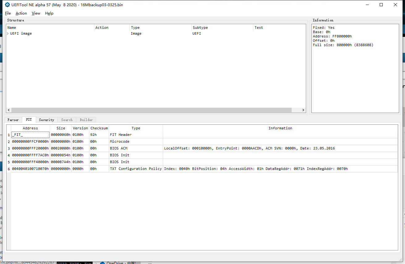
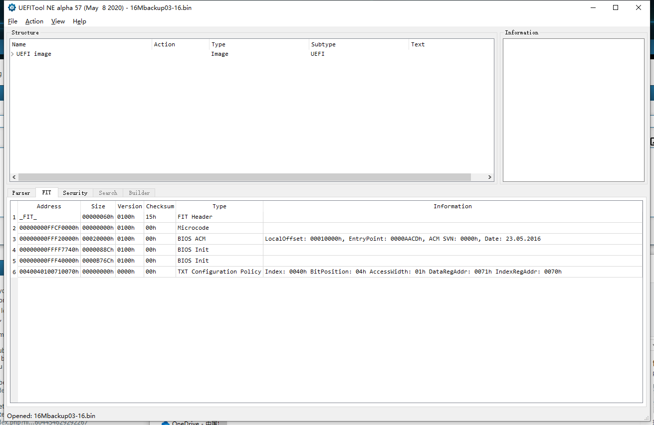
@carson512 - Show me what you mean about UEFITool not showing you FIT error if BIOS split. I didn’t split, but know how if necessary to check. My main concern there was invalid load of microcode due to microcode entry in FIT table broken FIT is blank in version 51 and only half populated in version 57, but that is with BIOS region as a whole. It may be that way from HP, some stock BIOS are just not built properly Thanks for BIOS images, I will look and see if I can translate those into the actual BIOS sections in the BIOS itself, since they do not use the actual section names (Main, Advanced, boot, Security) There is two platform modules, this is dual BIOS image, one half on top and one half on bottom. Search BIOS Lock Unicode with UEFITool NE and you will find both platform modules, or here is the GUID for both ABBCE13D-E25A-4D9F-A1F9-2F7710786892
There is no guide for this. On microcode, some systems simply cannot run without one. How did you remove it, FF the module out, or FF the body out only? Try the latter, leaving header in place.
PCIE and TDP are not menu/submenu sections, so you need to be more specific there. I get what you mean about the IIO’s, I will see what submenu they are in and try to make visible for you. For now, please test this BIOS below and tell me if you can see OverClocking Feature now, look in Performance Options and Advanced Options, not sure where it will go (if anywhere). Also, please show me what you can see inside both of those before you flash this, from top to bottom of each at root level inside. While you are doing that, please also show me inside root level of PCI Device enable/disable.
I’ll have to dig around, it may be they are not using platform at all for the displayed menu, since nothing matches name-wise I think this is the case and we’ll have to find what is being used and hopefully same options are there and hidden too (or no luck making visible) http://s000.tinyupload.com/index.php?fil…808057347274898
* Edit - Yes, it looks like RBUSetup is what is actually being shown/used, same as Platform there is two as well . If the settings you wanted are not in here, then you may not be able to make them visible (but we can directly change via BIOS edit, dumping vars possibly, or RU etc) And on that front, please also test this BIOS, and show me what all you see now at root of BIOS/Platform config page, can you now see >> Service Options, Special Settings, Debug Options? http://s000.tinyupload.com/index.php?fil…604454629292267
@carson512 - Yes, that is broken FIT table in both, incorrect microcode offset in the FIT table causes that blank entry (We can fix).
Thanks for test result, the code/info does not help me, and I did not use invalid opcode, so not sure what it’s referring to? I could however do the same edit a few alternate ways, but kinda waste of time due to >> But, that is platform edit anyway, so not visible to you now that I’ve seen BIOS images now, so we don’t need to worry about this one further.
So, now we know edits to RSBU can be made and function properly, please look over IFR output from those setups and let me know if anything missing that you need to be visible, or any of that can help with what you originally wanted etc? I cannot make items in platform visible, only what’s in RSBU can be made visible (if hidden)
The RSBU menu is enough.May be in the bios menu need use specially key to open the Platform menu.I can use IFR and RU.tool to do the same.Really appreciate for that.
Now is the microcode remove which is the originally wanted. 1. I try to change the HEX that CPUID of microcode.Than use UEFI Tool 57 shows:
is there a way to calculate the checksun… 2. I try to use UEFI tool 0.28 to extract 197DB236-F856-4924-90F8-CDF12FB875F3 to a raw fil which have microcode.remove the all 306F2 part from the raw file.than replace the bady.A new rom here. Than use UEFI Tool 57 to open the new rom which FIT and Secuity info all gone…Is the UEFI Tool error?Or the FIT table error. Which way is easier or need specified version UEFI TOOL to replace.
Is there a possibility that replace the Bios Region with other C612 board? I found the supermicro have the two cpus board…But it’s bios region is 12M larger than 8M. zip it to 8M or change the desp to use the entire 16M chip which it easy?
There is several ways to remove microcode generally, for that kind of mod. Remove only microcode itself, or remove the entire microcode module, or remove only the microcode entries and leave the header of the module, which are you doing? And, what tool are you using to do the actual edit? To fix checksum you mentioned is easy, but if you remove microcode there would not be any checksum shown by UEFITool 57, since that long microcode checksum like you showed above is part of the actual microcode. In this BIOS, microcodes (x2) are located in 8C8CE578-8A3D-4F1C-9935-896185C32DD3 >> 197DB236-F856-4924-90F8-CDF12FB875F3 as you mentioned, there is two of these volumes in the BIOS so you need to edit both same/same
And yes, FIT always needs corrected after you edit microcodes for sure, and often any other BIOS edit too. FIT was broken by default in this BIOS, and incorrectly setup too if the offsets were even correct to begin with (which they are not) FIT needs entry count increased to 2 microcodes by default not one, and then correct microcode offsets added. If you are removing microcodes, then you need to decrease total entry count by one (so remove original single microcode entry value) And then fix offsets of all other items in the FIT table via straight hex edit on entire BIOS as a whole.
So you want BIOS with 306F2 removed and FIT fixed? If yes, I can make for you from the dump you sent me. Don’t use UEFITool 28, it breaks this BIOS, and removes padding at PEI volumes on rebuild
Sorry, didn’t see your other reply until I posted the above. No, you can’t replace BIOS region from one board to another, too many things differ between boards for stuff like that usually (rare occasions maybe)
* Edit @carson512 - here is BIOS including mods I already did for you + 306F2 removed and FIT table fixed for microcode entry (so you will see fixed entry for microcode now, but only 406F1 is there) Additionally included is BIOS with fixed FIT table on BIOS that includes both original microcodes, so you can see how FIT Table should have been initially from HP http://s000.tinyupload.com/index.php?fil…215321482320073
here is the test result: MRBSUTestUEFI25306F2REMFITFix.bin can’t boot with tha same error that i remove the microcode… SYSTEM-25Q128FVSGMRBSUTest-FITFixed.bin can boot normal.Check the debug log with the backup bios.Look like the same.
here is the end part of debug log with first one MRBSUTestUEFI25306F2REMFITFix.bin
here is the normal boot log near
that may the key is ‘Loading PEIM at 0x000FFFBDC40 EntryPoint=0x000FFFBF870 HpSecPhaseErrorReportingPei.efi’ and try to use IDA with this efi file
change that ‘jz’ to ‘jnz’ than make other error. Maybe the HpSecPhaseErrorReportingPei just a error handler module? The code 275 was pass to the HpSecPhaseErrorReportingPei?
@carson512 - SYSTEM-25Q128FVSGMRBSUTest-FITFixed.bin is same BIOS I sent you already at post #12, but with FIT Fixed for both microcodes, so you can see how it should look in UEFITool NE Other BIOS = fail, this means your system cannot boot without microcode for the CPU, not all can and this must be one of those. Does the board have a service or management jumper? If yes, try that BIOS again with jumper in place and see if that matters or not.
Not sure on the assembly, if that would help or not I mean, if you want to bypass all that, I’d change that JZ to JMP >> hex >> 74 37 >> EB 37, so flow them becomes as you see below
There is two modules “HpSecPhaseErrorReportingPei”, Edit both and make the edit via direct hex editing on entire BIOS as a whole, that way PEI volume does not get rebased. Check post-edit file in UEFITool NE and make sure you don’t then need to correct checksum for those two modules, if so re-edit via direct hex on BIOS as a whole.
there is a System maintenance switch On board. I try MRBSUTestUEFI25306F2REMFITFix.bin with change Reserved SW(S3,S4,S8,S9,S10,S11,S12) to ON.Nothing changed…still show the ‘unsupported’ error. in the debug log : S3、S4、S12 add one log ‘Maintenance Switch** is set.’ S4 may change the debug log level. add some like 'Loading PEIM at 0x000FFF97FC0 EntryPoint=0x000FFF98B78 HpStatusCodeHandlerPei.efi ’ in the log at this phase can’t find nothing different.
there is 4 jumpers with pins. two of them is the COM pin(RX TX GND VCD),One is NMI functionality jumper(An NMI crash dump creates a crash dump log before resetting a system which is not responding.).One is just 3 pins near ME rom One GND and two 3.3V,and not mention in the guide.
with the debug log is loaded 13 modules before the unsupported error
The microcode check must in this module. Is that possible use IDA to chek which module call the HpSecPhaseErrorReportingPei.efi to show the unsupported error or just HpSecPhaseErrorReportingPei.efi itself.
use winhex to edit the bios file directly 74 >> EB the system boot without the ‘unsupported’ error and continue the progress. until the red screen show ‘PiSmmCore+00BA8Eh RIP address out of range’ error same as jnz or remove the HpSecPhaseErrorReportingPei module. but i realize that jmp is much better than jnz when the cpu change … The PiSmmCore is the modulethat load all SMM module? And searching the rom just PiSmmCpuDxeSmm module with the ‘RIP address out of range’ string and a SMM module.
here is the part debug log with ‘EB’bios
here is the part debug log with normal bios
before ‘SMM IPL closed SMRAM window’ this line. the log seem the same. in normal boot next progress is to load the EF827D89-960E-485B-9D0F-2850E6CB2BB0 which is HpstatusCodeHandlerSmm is that possible that the HpStatusCodeHandlerPei call the HpSecPhaseErrorReportingPei than HpstatusCodeHandlerSmm couse the RIP address out of range error. All log in the zip file below.
by the way.i just think the two bios region was stand alone. Beacuse just change the firest 8M bios part will effect.Unless in the bios menu to change the backup rom…Maybe the FIT will looks good after cut.
 However, without seeing the dump from each chip 1-2 I can’t say for sure what is what, but with Surestart it doesn’t matter.