Feel the BIOS chip with your finger when you try to turn it on, is it HOT? If yes, chip is in adapter backwards
Also, it looks like you are missing 2 wires, connect them all 
I knew someone would pick me up on that 
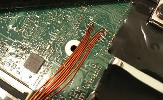
Extra wires added, and still no worky. All connections checked multiple times, and chip is not getting hot. I hooked the logic analyser up, and the clock signal is a bit variable, so I assume this is the problem. It’s trying to communicate, so I think it’s wired correctly.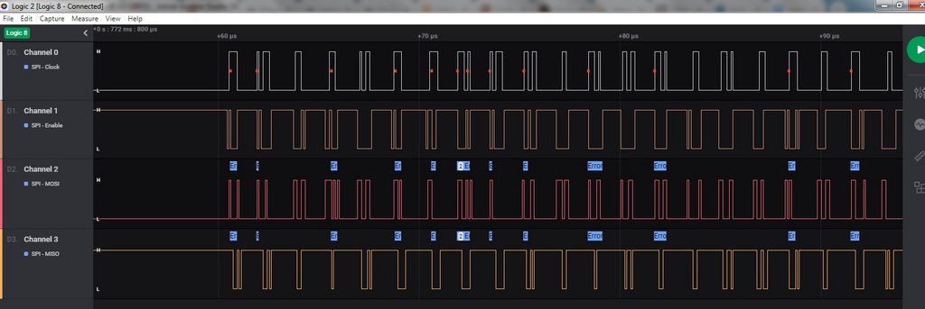
I guess my next step is to flash a chip, solder it back on, and see what happens. When the CH341 programmer arrives, I can see if it will flash in situ.
Thanks,
Ian.
Right then. CH341 programmer arrived today. All hooked up and appears to be working.
While I still had the eeprom connected to the motherboard on flying leads, I connected the programmer to the chip, and was able to read data from it. This hopefully indicated the motherboard isn’t loading any of the data lines, so in situ flashing could well be possible. Hopefully it will be the same when the chip is soldered back on the motherboard.
Thanks,
Ian.
@lfb6 - Just combined the two files you provided previously, and now have a BIOS file to flash to the chip. My UEFITool screen looks identical to the one you posted, and the size matches.
I’ll hopefully get a chance to test it out this evening (currently lunch time in the UK).
Thanks,
Ian.
Good luck!
@IanP50 - Main battery, and or PSU cable may need to be attached, before you can read/write to chip soldered to board. Some need this, both, or one or the other, some do not work with either connected (try this first)
What is the BIOS chip ID? Not all software can read or write to all chips (validly)
Oh yes, I should’ve been a litte more specific in my wishes  . But on the other hand there’s a lot of information on this item here. CH341 software 1.29 doesn’t write 128MBit chips for me reliably, happy with ASprogrammer.
Most pain will be to get the clamp in the right position. All programs have automatic routines for burning, but it’s anyway just blank, blankcheck, burn, verify. As an additional security one can read the chip after flashing once again, save the content, compare files…
Chip programmed successfully, and soldered back on motherboard. Laptop re-assembled and - nothing. I get three flashes of the led in the power button when the power is plugged in (normal behaviour I believe), but absolutely nothing when I press the power button. No led’s, fan, beeps or anything. I’ve checked all the connections, and everything looks good. This is the same as I was getting with the bios chip socketed on flying leads. I’m pretty sure the power button is good, as pressing it when I had the logic analyser connected did trigger communication with the bios chip, even though the clock was a bit funky, due to the flying lead arrangement.
Could a bios chip cause this sort of behaviour?
@Lost_N_BIOS - Noted. I’ll try various options if it doesn’t want to play nice. Bios chip is a Macronix MX25L12873F. No apparent issues programming it. It took about 5 minutes to program and a further 2 mins to verify.
Off to scratch head…
Ian.
Sorry to hear that. I assume you read the content of the chip back and compared it. If you can write to and read from the chip the chip normally should be OK. What program did you use? Did you program the chip before soldering it back? If you soldered it back already programmed- did you re- check when it was soldered?
If I understand you right then you put together p50_desc_gbe_me_fd.zip from #17 and the bios 86_with_nvram_pch00.zip from #13. One possibility would be to try 86_stock.zip as bios region (put together with FD/GbE/ME again) as a first step since your NVRAM could also be compromised.
But the fact that absolutely nothing happens doesn’t seem right. If I remember right you did hear some beeps after the bad flash, but didn’t hear them with the reconneted bios chip and everything was dead, right?
Did you put everything together again? My old Samsung laptops reject to work if the harddisk isn’t connected for example. A desktop PC would show you a normal boot and give you bios access without harddisk, the old SNB/IVB laptops (Phoenix bios, too) are dead without hd.
@IanP50 - Did you manually verify? Do this by closing app after write verify, then open again, read then verify, then save, then compare that with what you wrote. This can only be done directly after a write, without powering on system
If incompatible software is used, a false verify can and will happen.
For MX25L12873F use CH341A v1.31(1.4) (CH341AFree) (This is the name of the folder in package below), ASProgrammer 1.4 or 1.41, or CH341A v1.1.1.32. Yes, as lfb6 asked, what program did you use?
https://ufile.io/p21lj9ck
If it is a good write, which you’ll have to do again to confirm manually if you did not before, then new BIOS will need to be made. I’ll make you one.
Nothing happening is not good sign! Are you sure BIOS is soldered on correct position? If you are not, feel it while you try to power on, if HOT, then it’s backwards.
I can’t tell by your two images above, but it doesn’t look like there is a pin1 indicator on the PCB, so if you have an image pre-removal look at the chip’s orientation and make sure you put back same way
Also, looking at the images now, your first one, last pin under U5 side, are you sure pad was not removed there? I can’t tell for sure in that image due to it’s too small, and even zoomed in it’s hard to tell, but looks like maybe pad was lifted and is gone.
And now that I look again, 1, 2 on that side look that way too 

If you remove chip again, clean pads/area and let me see pads
@lfb6 - I’m using AsProgrammer 1.41 with a CH341 programmer now (was previously using a Raspbeery Pi running flashrom). I ran the verify routine in AsProgrammer, as I assumed this effectively read the chip content and compared it with what it had just flashed. Is that not the case? I didn’t re-check after soldering the chip back on the motherboard.
Correct.
I can try that. I’ve tried flashing the chip while soldered to the board, and it appears to flash correctly. I’ll need to make sure I verify the flash, but it appears I won’t need to remove the chip again.
Correct. I could try flashing my original ‘bricked’ file back to the chip and see what that does.
Yes, it was a complete rebuild. SSD, screen, keyboard etc.
As above, I just used the verify function in AsProgrammer. Sounds like that maybe wasn’t sufficient.
I’ll read the chip while soldered on the motherboard and compare with the code I flashed. What’s the best way to compare two BIOS files? I’m happy to flash as many different BIOS files as it takes. Apart from the pain of dismantling the laptop each time, it’s not such an issue now.
I’m 100% happy with the chip orientation, and it doesn’t get hot. I’m also 100% sure that there’s no lifted or damaged pads. It’s proving hard to get a really nice close up photo with my phone camera, but here’s a decent shot just after the chip was removed. I’ve hand soldered many surface mount components in the past. Some much smaller than a SOIC8. Nothing was damaged when I soldered the wires.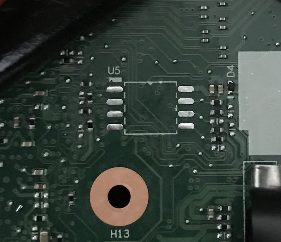
I think the white rectangle and the bump in the top line of the component outline indicate where pin 1 would be.
This was before it was removed. Focus isn’t great, but you can clearly see the orientation.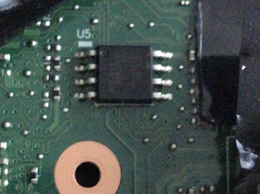
While the motherboard is exposed, I’ve just checked the eeprom supply pins, and it does rise to 3.3v just after pressing the power button. It only stays at 3.3v for a couple of seconds, but it appears things are happening on the motherboard, even though nothing obviously happens. I’m sure if I hooked up the logic analyser, I would also see some communication, much like I did previously, but hopefully with a more stable clock frequency.
Thanks,
Ian.
@IanP50 Asprogrammer 1.41 should work. I always restart the program, read the chip again, save to a different file and compare. Mostly at a command prompt fc /b file1 file2, HxD also has a compare function (Ctrl K, or ‘Analysis’, ‘Data comparison’) and there are countless other tools. Files should be 100% bitwise identical!
Regarding your old bios end the error beeps you could hear: Something might’ve happened between last boot try with error beeps and disassembling/ cable soldering what prevents system generally from beginning to check bios.
Could you reproduce these error beeps before disassembling when trying to reboot? Were they still there after a power off/ disconnect battery/ mains? Flashing your corrupt bios would only make much sense if you had reproducable error- beeps before disassembling. It then could make sure that communiction with bios chip works as before.
Orientation looks good, there are marks for orientation in the rectangle, too.(D4 on the right side looks as if it had been touched recently?) Regarding soldering pads, they look OK to me, but almost all pads do have a SMD compenent connected very closely, so one could check connection quite easily.
Socketed CPU? Re-seat RAM?
I’ll read the chip and compare with the original.
Yes, it was very repeatable. Didn’t matter what I did with battery, AC power, CMOS battery etc. Every time I pressed the power button, I got the two sets of five beeps.
All pins have good continuity to surrounding components, so connections are all good. I didn’t get anywhere near D4 with the soldering iron. I think it’s just how it looks on the photo. Looks fine under magnification.
No sockets for CPU I’m afraid. I’m not sure you do very much on a laptop. I did try re-seating the RAM.
I’ll try a bitwise compare of the eeprom and see if it matches. If it does, Ill try the original ‘bricked’ bios and see if I can get it beeping again.
Thanks,
Ian.
@lfb6 - Fresh read of chip compared to original file was 100% identical, so flash was good. I used HxD to compare.
Just re-flashing my original BIOS to see if I can get any beeps.
Thanks,
Ian.
@lfb6 - Progress has been made. Flashed my orignal broken BIOS back to the chip. Re-read and compared. All checked out fine. Powered up, and no beeps, just three flashes of the power LED. Had a quick Google of the three flashes, and people suggested disconnecting the CMOS battery for a few seconds. Tried this, and when I plugged the power back in, I was happy to hear my five beep sequence again.
Just flashing the p50_desc_gbe_me_fd.zip from #17 and the bios 86_with_nvram_pch00.zip from #13 back onto the chip to see what happens. Fingers crossed.
Thanks,
Ian.
@lfb6 - More progress. Flashed rebuilt code, plugged power in, three flashes again. Pulled the CMOS battery, and this time I have the power LED staying on, fans cycling, and after a while, heard the sort of beep you hear when presented with a boot message. I need to put the screen back on to see what’s going on, but we’re not dead anymore.
Thanks,
Ian.
@IanP50 Congratulations, nice work! I hope you get a picture when reconnecting the screen! But the beep means normally ‘Post finished’, so that should be a good sign!
Read the/a ThinkPad P50 Hardware Maintenance Manual and there’s only mentioned 3 blinks when connecting to power, nothing more. (For "Five short beeps, pause, five more short beeps, and
pause" it says "Replace the system board"). But clearing CMOS
Your stuff’s too new  All my Samsung (2 Sandy Bridge, 2 Ivy bridge) and my Fujitsu laptop (Merom) were socketed.
@lfb6 - It’s not all good news I’m afraid. Connected everything back up, and not getting anything on the screen. I get a quick double beep after approx 30 seconds. Power light remains on. After about 1.5 mins, the backlight on the display comes on, but still nothing on the screen. After about 2 mins, I get another double beep with a slightly longer gap between beeps.
It looks like the keyboard works to a point, as num lock and Fn lock LED’s go on and off when the keys are pressed.
I can hear the fans speeding up and slowing down, and occasionally see the disk activity light flash, although that appears to have stopped now.
Only things not connected are the WiFi card and the second storage HDD. Windows OS is on the SSD which is fitted. I wouldn’t expect either of these to stop the display working though.
Could we still have a funky BIOS?
Thanks,
Ian.
@IanP50 Well, would’ve been too good to be true. But I’m pretty sure we get i up and running again!
There are some possibilities here.
- Transplanting the NVRAM of the old bios was kinda optimistic, but would’v been the easiest solution if it’d have worked out.
- Your ME might have som corruption.
I’d propose as next step taking a clean stockbios region and combine it with the FD/GbE/ME region with open flash descriptor:
- Unpack 86_stock.zip from #9 as bios region and put together with same FD/GbE/ME as before (p50_desc_gbe_me_fd.zip from #17) and program it into the SPI. Should have same size and same look/messages in UEFItoolNE as the version you did try now.
If this doesn’t work we’d try stock bios with a cleaned ME (you don’t have that yet).
(And if that doesn’t work we’ll ask @Lost_N_BIOS who really knows a lot more about this stuff!)
@IanP50 - Ahh, great to see those clean and nicely tinned pads all still in place  Those previous (tiny) images had me worried, but as I mentioned I couldn’t see it all very well, glad to see all is OK
Yes, looks like the white block is, or can be used as, pin1 indicator, since that before image has pin1 there
Wow oh wow, that is a lot of quotes taking up a lot of space, very hard to consume like that, especially while having scroll up/down past 7-8 posts to type out my reply 
You cannot always rely on programmer software verification, unless/until you already know for sure via previous bootable success of flashing of this exact chip with that exact software, or manual verification
Manually confirm via >> after writing in BIOS, without powering on, close program, open program Read, verify, save, then compare with what you wrote in hex editor.
You only need to do that once, then you know the software is writing to this chip correctly, and you can then rely on the software verification routine.
This needs to be done directly after write, without power on attempt, otherwise data changes (Sounds like you’ve already done all this, but I didn’t read on until I’d already typed it all out, so there is lies )
Is this a new LCD, or the original? If a new LCD, test external display connected, if there is external connectors, to rule out faulty/incompatible LCD. Plug those in, one by one as you test, with system off, before you power on (don’t live switch them while testing like this)
Yes, may need cleaned ME FW. I will make you some BIOS if you guys don’t end up getting it sorted out.