Hi,
My Lenovo P50 locked up during a BIOS update from inside Windows (Win10). After several hours, all I could do was remove the battery, and now I have a dead laptop.
I’ve done lots or research, and have configured a Raspberry Pi with flashrom, and can now read/write the eeprom chip that I’ve removed from the motherboard, but I need to extract the BIOS from the Lenovo BIOS .exe file, so I can flash it back to the eeprom.
This is a link to the latest version of the BIOS update from Lenovo. I had to remove the https from the start of the URL to get it to post.
//pcsupport.lenovo.com/gb/en/products/laptops-and-netbooks/thinkpad-p-series-laptops/thinkpad-p50/downloads/ds106108
Can anyone advise how to extract the Intel Bios image from this .exe file?
I tried to provide a dropbox link to the Lenovo update file, and also my bricked bios .bin file, but I don’t have enough posts to do this.
Any help and advice would be most appreciated.
Thanks,
Ian.
Unpack the Lenovo exe-file. In the \DRIVERS\FLASH\n1euj44w???.???\N1EET89W folder you’ll find 5 files, $0AN1E00.FL1 can be opened with 7-zip, contains 6C60EE00 (8 MB) which has similarity with a bios region.
Be careful, that’s not a complete ‘bios’, flash descriptor, me, gbe… are missing!
Thanks for the info.
I’ve kind of got that far. Any idea how I can get a complete bios flash descriptor?
Would it be possible to use something like this to repair my corrupt bios image?
Cheers,
Ian.
@IanP50 It would be very helpful if you could post what’s left of your ‘bios’- you wrote you were able to extract it? Don’t try anything before you have made a backup of everything that’s possible and you got your backup reviewed!
Hi,
It’s too large to attach here, but here’s a dropbox link to the bricked bios.
https://www.dropbox.com/s/yyr7dfww1uyjn8…kedp50.bin?dl=0
Thanks,
Ian.
---------------
If you can’t access the file on dropbox, I can upload it anywhere that works for you.
Thanks! It seems that the other parts of your bios are not harmed- FIT opens the backup- image without complaints. The reason why you possibly can’t boot might be visible in the picture…
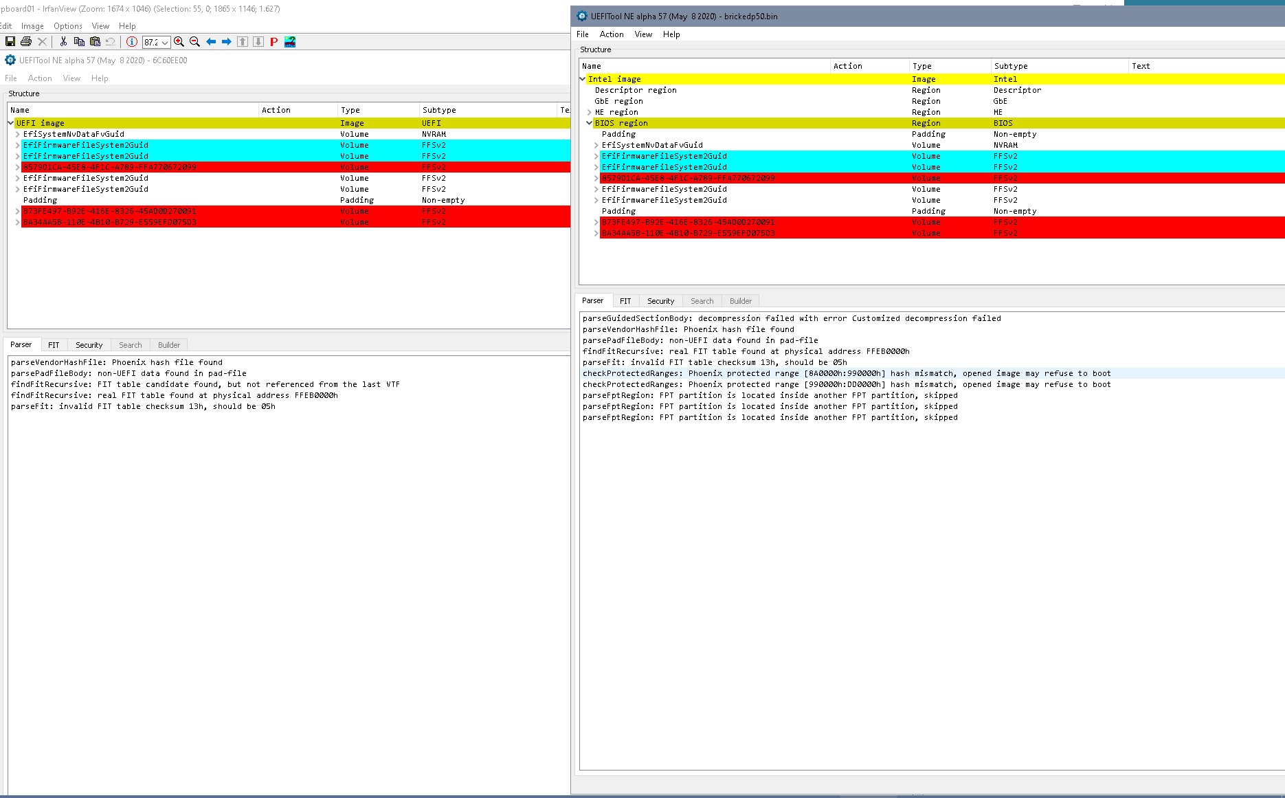
As you can see the structure in the update is not exactly the same, so it’s not just to exchange the bios regios with the update file. In addition there might be some specific information in your old bios like serials, for example, which one would like to keep. Old bios was 1.59?
Personally I’d like to keep as much as possible from the old bios. So I’d start comparing the different volumes in bios region and would as first step possibly just exchange the protected regions that were mentioned with ‘hash mismatch’. There’s in addition a possibility that there’s additional information correlated to these protection mechanisms that needs to be updated, I don’t completely understand the structure of the Lenovo update and I’m not very experienced with these newer protection mechanisms.
@Lost_N_BIOS Do you have an idea how to proceed most safely here?
Hi,
Thanks for your continued support 
Yes, I believe the old bios was version 1.59. If I can get that version fixed and back on my P50, I’ll be a happy man.
I wonder if the structure of the 1.59 download from Lenovo would better match my bricked version (assuming you were comparing to 1.62). I’m a little outside my comfort zone swapping sections of bios.
I guess my main concern is how many times I can solder/desolder the eeprom chip to the motherboard before the pads start to lift. I assume this may be a bit of trial and error to get right.
Thanks,
Ian.
@lfb6 - Boot Guard is possibly active here, be VERY careful what you edit and how  If you do any swaps from stock BIOS RGN to FD/ME + original BIOS RGN, do all volume replacements via direct hex swap in otherwise if tools are used to rebuild then boot guard will be violated.
Generally, first try 100% stock BIOS region, then later, if OK, you can try to add back in original NVRAM via second edit and reprogram, or FPT flash in etc. If you leave in original NVRAM at first, it may be OK, but hard to say since it bricked.
I always help user both ways during this kind of recovery, stock NVRAM then original as test to see if brick or not.
Yes, serial and UUID, LAN MAC ID etc may need swapped back in possibly in a few places, but getting up and running first is most ideal goal, that’s why I suggest 100% stock (empty/sparse NVRAM) at first, then later you can test adding back original NVRAM
The same line of thought on NVRAM that I mentioned, I also apply to those two main padding files, if they contain user specific data such as serial, UUID etc (sometimes that can be messed up too)
One of the paddings may be EC FW, I have not looked at this BIOS yet, I was waiting to see if you’d sort it out for them first. I do see copy of EC FW in stock EXE = .FL2 file, and yes EC FW = first main padding in BIOS dump too.
Also due to boot guard, and potentially using some of the original BIOS info/NVRAM/offsets etc, I would do the recovery with same BIOS version as the bricked BIOS. Then only unlock FD and then clean/UPD ME FW just in case it’s messed up
@IanP50 - If you are not familiar with desoldering BIOS chips, especially lead-free attached ones, then it’s probably best for you to get SOIC8 / SOP8 test clip instead.
It’s tough to get BIOS chip off easily if you are not familiar with doing such on lead free boards. Generally, you’ll want to add a TON of solder and keep lots of flux on there, so huge blob on both sides, heat up both as much as you can and then gently lift one side at a time
Alternating the heat between blobs so you can try to keep both as hot as possible do you don’t trash the BIOS legs as you lift it out of there. Then once chip off, clean up/off all your huge solder blobs and get pad/area ready for chip to go back
Since you can read/write to the chip with Pi, there’s no need to remove, so why has removal been mentioned? Or, did you already remove chip to read/write via Pi? If yes, OK, I gotcha then
For such concerns, it depends on how safely you add/remove now, just be careful, don’t go to hot and it will be OK, always use lots of flux and do not press hard onto pads when wiping clean/prepping for placement back
Also lower heat once chip is off there, and once you do have it off, then you can always use much lower heat than originally, because I assume you will now be working with leaded solder so you don’t have to get it so hot as that initial removal.
If you need link to cheap programming kit + SOIC8 test clip with cable, let me know, I can link you to amazon or ebay, price usually $7-$13 for cheapest kits
Since version seems to be an issue here, as soon as up and running, I suggest you manually update to the latest BIOS yourself via the stock EXE method, that way windows updates does not brick your system again trying to do it’s own update.
You can stop windows from getting drivers/BIOS by editing windows update options, uncheck/exclude “Drivers From Manufactures” in the advanced options
Do you have an image of your BIOS MAIN page from before it bricked, so I can see UUID, Serial? If yes, please upload. I can see MAC now, so no worries there
I could make you BIOS now, but since you are removing/putting chip back, I’ll wait until I know serial/UUID so I can see about putting those back first
@Lost_N_BIOS Tried a stock bios ‘N1EET86W’ = 1.59 and same version with old NVRAM transfered- both versions don’t have the warning in UEFItoolNE if you take the whole bios- but they have a bootguard warning if you take the biso region. I assume this should be OK?
86_stock.zip (4.22 MB)
86_with_nvram.zip (4.24 MB)
@Lost_N_BIOS - I’m actually quite experienced at soldering in general. Not done much on motherboards specifically, but plenty of SMD work. I’ve got some ChipQuik low melting point solder which keeps the temperature down. I should be fine - hopefully 
I had to remove the BIOS chip because it wouldn’t read when mounted on the motherboard. I assume something was loading one of the data pins. Everything was fine with the chip removed
I’m afraid I don’t have an image from my BIOS main page. Foolishly, I thought it was something I’d never need. Regarding the UUID & Serial etc, I believe these can be added back into the BIOS using the Lenovo Hardware Maintainence Utility assuming I can get it to the point where it will boot. This is apparently what Lenovo engineers would use if they replaced a motherboard in the field. I have managed to get a copy of this utility.
I don’t know if it’s of any use, but I think I’ve managed to find a copy of another P50 BIOS chip dump. As far as I can tell, it’s from an earlier version - 1.49 I think.
https://we.tl/t-fHNgf2RvQH
Thanks,
Ian.
-------------------
If it helps to find it in the BIOS files, here’s the serial number and machine type from my P50.
@IanP50 Your good P50 bios does contain nothing else than the EC FW in the first MB of padding, too. That was the only unclear region since it wasn’t included in the stock bios and the region from your dump might have been damaged. I built a ‘stock bios region’ for this version from Lenovo stock bios the way I did for the 2 bios files attached earlier- differences to the ‘good’ bios region only in NVAR region.
I’d think it’d be a good idea to stop soldering and buy a cheap SOIC clip… Had to remove a pin from clip for my old Samsung NB, there were pins 3 and 4 connected on the mb- you don’t need all 8 pins anyway. I own a 866 programmer, too, which always gives a shorting warning and isn’t able to flash ‘onboard’ since board is drawing too much current. Cheap CH341 programmers don’t care. Sometimes you see the programming light ‘on’ just when connecting, I suppose that are these cases where there’s too much current ‘disappearing’, but flashing works anyway…
If you’d be able to reflash without soldering I’d just go on, combine FD,GBE, ME region with the stock bios region to a complete bios and flash it…
p50_desc_gbe_me.zip (3.82 MB)
@lfb6 - No warning is maybe because you’re not looking at a complete BIOS, Boot Guard is burned into the PCH if active, so whatever BIOS or ME says in settings etc does not matter. But, I am not 100% sure what you are saying there
If you mean Boot guard warning in UEFITool, do you mean boot guard hash broken kind of warning, or what? You should not see any boot guard or hash warning in parser tab, if that is what you mean
If you rebuild anything here, do it one volume at a time only, via hex only, do not use tools and do not swap entire regions etc. << As of here, I did not look at your attached files yet, below comments are after I did
The files you attached can’t be used by IanP50, this is not complete BIOS, I assume you know that but just saying so he doesn’t grab and try to program… They both look OK in regards to Boot Guard though
The Boot Guard warnings on his dump is because the BIOS is corrupted, Main DXE volume and one before or after (I forget which) is corrupted and does not expand properly, so that breaks the boot guard hash
The corruption and Boot guard violation either would brick the system, so probably combo of both caused the brick here.
I checked again real quick, yes, it’s the main DXE volume and one after that that are corrupted >> 9E21FD93-9C72-4C15-8C4B-E77F1DB2D792 + DAB78572-E8D1-4C3F-9A1E-F27E9CAF686D
If he wants to test your BIOS edits, these need put back into complete BIOS via hex (FD/GbE/ME + your files) Do not clean ME FW at first, so we can see if it’s OK, because sys specific info is in there that will be wiped on clean/UPD
If it’s still a brick after that, with either of your BIOS built into full, then possible ME FW issue and go ahead and clean/UPD to test and see if this is issue or not. Unlock FD in BIOS you send him too, it’s OK to edit this from the start
* Edit - EC FW is in stock BIOS package, see LF2 file
@IanP50 - Great to hear your already familiar and ready for solder/desolder, yes, chipquick will help plenty with initial leaded solder removal.
Yes, you can add info back with Lenovo tools, sometimes, if you have the info and a compatible set of the tools. The reason I asked for the images is to find it easier in your BIOS dump
Which set of tools for Lenovo do you have? Send me a copy, in case it’s different than what I have, thanks!
Other dump does not help here, but thanks, I have some others already too if we needed. I can fix your BIOS as it is, just hoped you knew your serial or UUID so I could locate to put back for you
Thanks for the image, I will see if I can locate the info from this… Yes, I see Serial >> I only see serial in ME FW, which is not ideal, if we have to rebuild your ME FW as that will be erased.
So, we need to test a BIOS with ME FW as-is, not cleaned/Updated, to preserve the info there in case this is where BIOS polls the serial/UUID info from
So to me, sounds like you may need to test multiple files, so FD should be unlocked and BIOS Lock, SMI/SMM Lock (if present), and FPRR should all be unlocked (in NVRAM edit only, if possible, due to boot guard) in any initial BIOS you program in.
That way best chance to do any follow up flashes to fix info can possibly be done via FPT software.
I checked, and there is no FPRR “setting” for us to disable, so if this is set via module lock, we can’t disable due to it would be covered by boot guard.
BIOS Lock is disabled already in setup, but IS enabled in NVRAM, so this needs disabled >> lfb6, search this string on entire BIOS as a whole >> 01 00 00 01 00 01 00 01 00 01 00 00 01 00 01 01 01 << Change last 01 to 00
That only leave FD to unlock, and then FPT flash of BIOS region would be possible, or volumes within BIOS region if necessary, unless FPRR is set << If this, then it may be possible to FPT flash some areas, but we can’t tell until you’re up and running. And it could also mean no FPT flash due to FPRR, we’ll have to see
BIOS could have S3 sleep bug too, which would bypass FPRR, but we can’t know this until system is running either.
@Lost_N_BIOS
Yes, warnings in parser if bios region alone is scanned. Combined with FD/GbE/ME to a complete bios my stock and stock_with_old_NVRAM bios regions don’t have warnings in the parser.
Attached FD, GbE, ME region in last post was ME from IanP50s dump, didn’t clean it since it opened without warning in FIT. Didn’t do anything to flash descriptor as well, assuming that this bios would be locked anyway.
Used stock ‘bios’ as is, combined with EC FW with hex editor. NVRAM extracted with UEFItoolNE ‘as is’.
As written: Compared ‘good’ P50 bios with same bios version put together from Lenovo EC fw and Lenovo stock bios- only differences are in NVRAM region. So if ‘my’ stock bios with transfered NVRAM (hexeditor) works all could be fine.
[edit]Attached bios region with changed bit, in stock this area is still empty/ FF[/edit]
[edit]Do you happen to know a magic string for removing flockdn for HM75 chipset, Phoenix bios?[/edit]
86_with_nvram_pch00.zip (4.24 MB)
@lfb6 - I don’t see any Boot Guard warnings with your edited BIOS regions, only expected Phoenix Hash warnings if edit was not correct, which is not related to Boot Guard
* Edit - Ohh, I see, you check with 57 not 51 There should be no Phoenix hash warnings on fixed full BIOS, no matter what you see on stock BIOS.
I checked two working user dumps, those warnings on stock is only due to those files are incorrect size, outside of complete BIOS etc, so offsets are incorrect.
And sorry, that is what I meant to say above when I said there was hash warnings on his corrupted dump 
Any BIOS with this Phoenix Hash error may not be bootable too, this is aside from Boot Guard concerns or warnings.
Yes, hopefully your BIOS with NVRAM transfer in is all OK
Broken ME FW does not always give any warning in FITc, better to check that with ME Analyzer (as a general rule, or initial check before you check with FITc)
Yes, stock NVRAM this BIOS Lock edit would not help, since NVRAM wont be built until first run, so whatever you put there will be overwritten with the default enabled value
FD unlock will help with ME FW flash in future, if any possible issues, so programmer would not be required if ME FW is corrupted. That’s the main reason I mentioned to unlock it, it’s already unlocked for BIOS region
Sorry, I don’t know anything about flockdn, if you’re looking to disable FPRR/BIOS Lock type setting that’s not controlled by setting but rather within a module (like you see edit info for here, maybe I can help, link me to the BIOS and I will look
@lfb6 - Thanks for your continued assistance with this. I’m not sure I understand everything you’re doing though. All this BIOS stuff is new to me. I’m happy with C++, Javascript, HTML, CSS and a little bit of Linux, but manipulating hex files is a new one for me.
I’ll order up a cheap CH341 programmer. Hopefully this will allow me to flash a mounted BIOS chip. I also wondered if I could solder some flying leads to the moterboard pads and then use my SOIC socket to hold the chips. This would allow plenty of test flashes without risking the motherboard. I’ve got some fine enamelled copper wire that would do the job nicely.
@Lost_N_BIOS - As above, many thanks for sticking with me on this.
Here’s a link to the Lenovo Hardware Maintainence Utility that I’ve got. It’s version 1.9, although I believe there is a newer version.
https://we.tl/t-PIoPxqfZTB
I’ll see if I can get my test socket wired on flying leads, and will report back when I’m done. We can then flash as many times as we want.
Thanks,
Ian.
@IanP50 - You’re welcome! Don’t worry, we’ll get it one way or another
Yes, leads to a socket would work. Thanks for the Lenovo Tool set - here’s the two sets I have, I think this is totally different thing than what you linked And, the “NormalTool” is not just for Y7xx systems
@IanP50 You’re welcome.
If you decide to solder the chip back, I’d flash it first with the bios with your own NVRAM/ settings, and the unlocked FD, GbE, ME- just give it a try.
Take a hex editor (HxD?) and simply put the content of 86_with_nvram_pch00.zip (post #13) at the end of the content of the attached p50_desc_gbe_me_fd.zip
That should give you a file that has exactly 16 MB and looks in UefiToolNE v57 exactly like that, no other readings in parser:
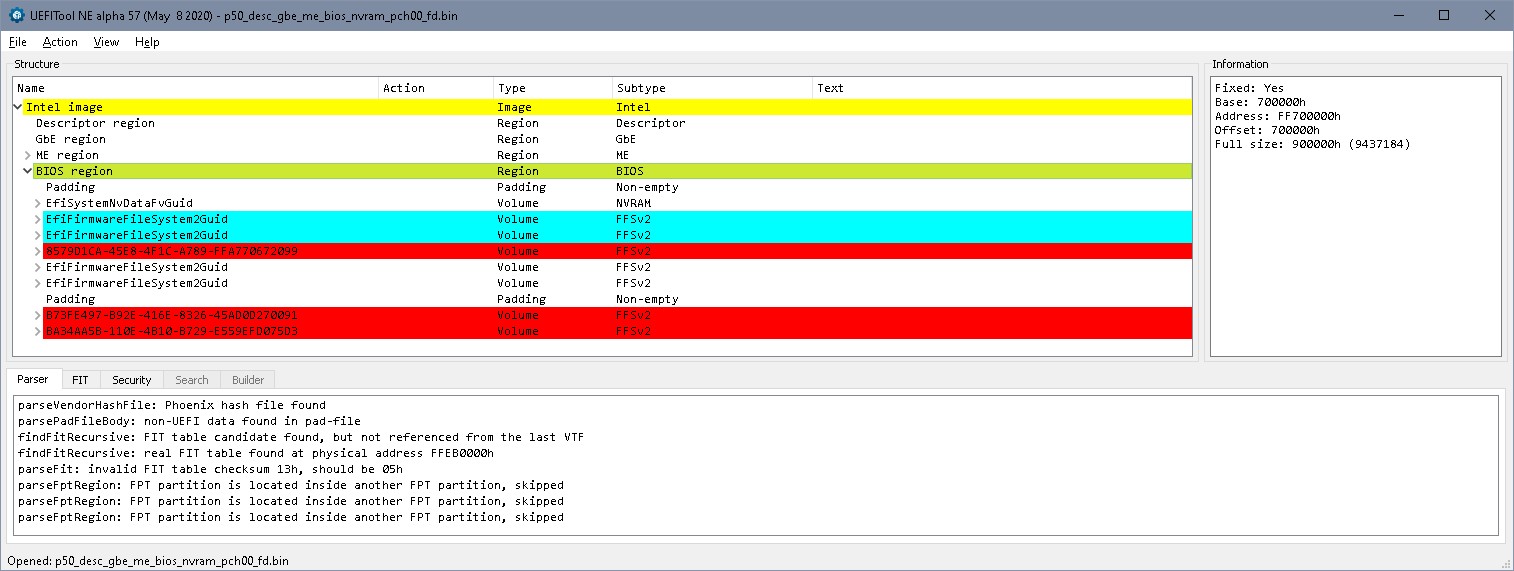
(This bios region has write protection disabled, and the flash descriptor is unlocked for all areas, so in terms of protection this is not ‘ideal’)
p50_desc_gbe_me_fd.zip (3.82 MB)
I added flying leads to the eeprom socket, but I’m not sure it’s happy about the long wires. When the bricked eeprom was still fitted to the motherboard, I used to get two sets of five beeps when I pressed the power button. I’m currently not getting anything. I’m going to hook up my logic analyser and see what the signals look like. It’s possible the motherboard is running the SPI clock much faster than the Raspberry PI, and the long wires would probably upset that.
I should get my CH341 programmer tomorrow, so plan B is to solder an eeprom back on the motherboard and see if I can flash in situ.
@lfb6 - Thanks. I’ll take a look at that, and see if I can get something to try.
Thanks,
Ian.
@IanP50 I’d be interesting to see a picture of your setup. What socket are you talking about, didn’t you mention that the chip was soldered to he board. I’d assume that the motherboards SPI clock wouldn’t do too much when notebook switched off?
@lfb6 - I’m using this socket - https://www.adafruit.com/product/1796
I have wires soldered to the pads on the motherboard, which run to the socket, which contains the eeprom. As far as the laptop is concerned (in theory at least), it does have the chip soldered in place. It just happens to be 8" away on the end of some wires.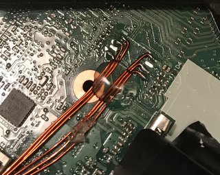
If I can get it to work, it would allow me to power up the laptop to test the bios code, but also to flash the eeprom as many times as required, but not risk the motherboard due to multiple soldering events.
Looks like my CH341 programmer has been delayed, and won’t arrive until tomorrow now 