Hi everybody! I am new here since last month, and I came here when I was looking for answers for my Intel D2700MUD motherboard.
Motherboard Model: Intel Desktop Board D2700MUD <Official Page>
Motherboard BIOS: Version 0076 (Latest) <Official link>
The board has a mini PCI-e slot and that’s where the problem comes from. I’ve found an SSD with mini PCI-e interface(it’s combined with Marvell 88SE9170 controller, not just mSATA interface) in recent and installed it into the board, the SSD did listed in the BIOS boot menu, however, after installing OS(Windows/Linux) the SSD is not booting when selected(not even disabling onboard SATA), board kept saying “No boot device has been detected…”, there is an EFI module in BIOS that supports basic UEFI boot, yet not helping.
I also tried Grub/Clover/Duet to boot from USB drive and then chainloading SSD alternatively, but almost no success, take Grub for example:
Under BIOS mode, Grub detects SSD when onboard SATA got disabled(or it’s enabled but all other HDDs unplugged), and I was able to setup/chainloading OS successfully, but once onboard SATA got enabled and all other HDDs running, Grub no longer sees SSD, and chainloading failed.
Under UEFI mode, Grub never detects SSD no matter what, therefore chainloading is not even possible…
So… after studying different tutorials, I tried to look into the BIOS file, but the file seems a bit tricky and can’t be opened normally by those tools(i.e. MMtool, UBU…), I’d like to ask for help here.
I appreciate any help or hint!
To mod this BIOS you need flash programmer (CH341A + SOIC8 test clip cable), then dump BIOS, mod, then reprogram. You can mod stock BIOS, but you can’t flash it, so using programmer is only way for Intel boards.
Is this NVME SSD or regular?
Either method you mentioned (BIOS/Legacy or UEFI) may work, but you may need to do a clean install each way. And for UEFI mode, you need to install to GPT partition (on the disk) from a GPT partition (On USB)
Hi Lost_N_BIOS, good to have you here!
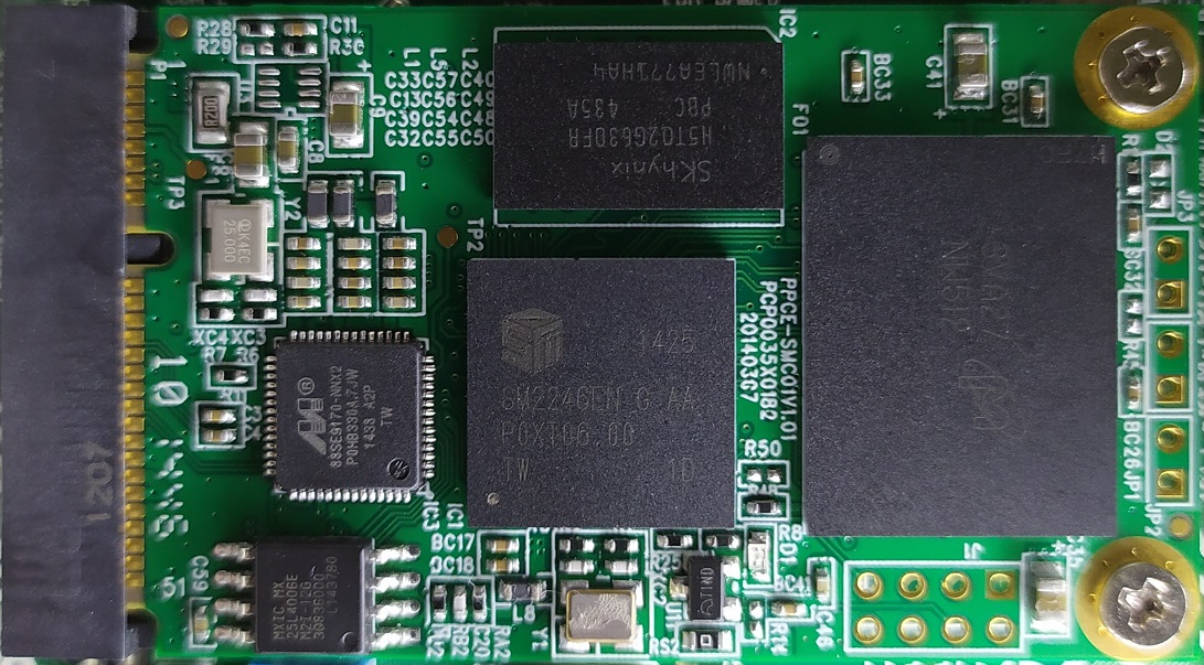
It’s an NVME SSD with Marvell 88SE9170 PCIe SATA controller + Silicon Motion SM2246EN SSD controller.
Both methods I’ve mentioned above is not working at this moment, although the BIOS found the SSD, but those Boot Loaders could not see the SSD when booting, that makes me focus on BIOS level.
You’re right, I did choose various disk layout depending on different mode, kept switching USB sticks for countless times. xD
The first problem before I get in BIOS file is, the tools could not open that BIOS file normally, only mmtool v4.50 could open it, but there are only 2 entries, um…do I need some specific applications to begin with? Thank you for your help!
Thanks, and you’re welcome! To use NVME, it would be easier to do the NVME Mod to the BIOS, but it would be possible to use bootloader methods without BIOS mod once you figure out those methods.
I have no experience with that, so can’t really help, you’ll have to ask on the bootloader method threads for advice on getting those methods working. BIOS Found SSD is normal, that will always happen, but you can’t boot to it unless you either mod the BIOS or do the bootloader methods properly.
I would give all details and ask for help in the Duet and Clover threads, I’m sure someone can help you get that going from there.
I checked your BIOS, and it looks like most/all settings are visible to you already, so really only mod to do would be the actual NVME mod which then you could use NVME without bootloader
To do that you need to either dump the board with FPT after doing Pinmod to unlock the FD - see “E1” (Or if there is service/ME/FD/FDO 2 pin jumper on board that would work), or use hardware programmer as mentioned.
The “proper” tool to edit the stock BIOS settings (.itk/.bio) is Intel Integrator Toolkit (Version 5.0.3.568 will work, it will open older version since this is old BIOS, but I suggest using that version). If you can’t find it let me know and I will upload a copy for you.
Nothing to do here though, maybe a few unrelated settings you can make visible, but it wont help with this SSD stuff 
Sounds like you had it working those on “BIOS/Legacy” mode, but then you connected other SATA devices and it then failed, correct?
If yes, then you may need to only connect these devices to certain SATA ports, sometimes when mSATA/MiniPCIE is connected then some SATA ports are disabled, you’ll have to check your manual over for this info.
Thank you Master Lost_N_BIOS for your direction!
I’ve read through the “Pinmod” thread, lucky for me, the D2700MUD integrated Realtek ALC662 have DVDD(3.3V) and SD_OUT pins as well, however, I prefer “E7” way as it’s direct and more reliable IMHO. ![]()
I’ve also managed to find/download ITK v4.0.3.280/v5.0.3.568 setup files, and open the BIOS file normally, well, like you said, “Nothing to do here”, HA…
You are correct about the last thing you mentioned, the board have 2 SATA connectors, bootloaders couldn’t detect PCI-e SSD once a SATA drive is working(since I’d like the PCI-e SSD and 2 SATA disks working together), therefore chainload on BIOS/Legacy mode wouldn’t work anymore, it seems native onboard SATA have higher priority than PCI-e add-in SSD, the manual stated little about PCI-e slot except all its resources((IRQs, DMA channels, and I/O space) are auto-configured, could this be a hardware resource conflict which could not be modified?
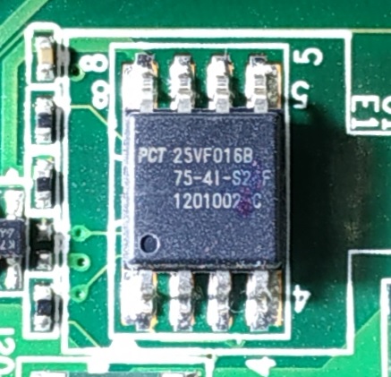
The last question is programmer related, the model of SPI flash on D2700MUD is 25VF016B, from SST most likely, I’ve checked for some CH341A adapters before purchasing, and it says ‘read-only for SST 25 series flash’, should I look for another programmer model?
Thank you.
You’re welcome @simhfc - Yes, I prefer programmer / E7 as well
I was thinking originally mSATA/MiniPCIE slot, when I thought maybe check manual and see if SATA slots get disabled, now that I look again and you mentioned PCIE to remind me, that kind of thing doesn’t generally happen (SATA disabled if xx PCIE slot in use etc)
Is this a normal PCIE Slot you are using, or a mini one like mSATA slots? If mini, then my original thoughts may still apply, but this should be mentioned in the board manual if so.
I’ve never heard of this issue with CH341A and your chip, maybe that’s true for some version of the software, but nothing like that pops up in 1.30 or 1.34 I just checked. And if the chip is somehow write protected you can change that with ASProgrammer software, then regular CH341A software would be able to write to it.
I bet the seller, or who ever originally wrote that, then possibly copied by others without checking, either didn’t know how to unlock, or only their specific chip they tried was locked and they didn’t know how to unlock, or they were using wrong/old software version when that was written or something like that.
I do see this is “Possibly” true for SST25VF010, but above thoughts still apply there too 
I see here, post #6 - user purchased your exact same chips and flashed them with CH341A without issue - http://andybrown.me.uk/forum/index.php?topic=24.0
Then next guy has issue, so see my thoughts above, probably that again there too 
Also, no issue here with CH341A and your exact chip, so I bet either some were using old software when this became a standard to repeat all over the internet, or some chips may be write protected, which you can remove
https://hardforum.com/threads/h8qgi-f-bi…rupted.1894360/
See also, MCZION reply here, translate first - he mentions changing security protection settings like I thought, using ASProgrammer, so again my thoughts seem to be correct and I bet he and others just didn’t do this correctly.
http://4pda.ru/forum/lofiversion/index.php?t884713-520.html
Is this BIOS soldered to board, or in a socket? If soldered, yes I know a more expensive non CH341A based device you can purchase, but it’s $16-24 and you need to additionally purchase SOIC8 test clip + DIP8 PCB (Usually sold as one), or know how to solder/desolder easily.
Maybe flashcat? https://www.ebay.com/itm/290587546215
It lists compatible with SST and PCT 25VF016B
Or a flasher called TL866, replace by new model TL866II
http://www.autoelectric.cn/en/tl866_main.html
The CH341A Chipset itself supports this chip as you can see here, no restrictions mentioned
https://www.electrodragon.com/w/CH340
And no warning like that here on this China listing either
And plenty of other listings on ebay didn’t copy/paste that warning either, so they have it listed as compatible too.
https://www.aliexpress.com/i/32666439987.html
It’s so hard to know for sure without any on hand to test I do notice where it says this, it always says ESMT SST, instead of just SST, is there maybe a differnce? If you want to wait, I will order some of these from China and test and let you know?
I will go ahead and order these now, since I spent so long looking, I’d like to confirm what’s going on here. Please give me the full info off your chip, or take a good image and send to me
Wowoow~ Mater Lost_N_BIOS, thank you so much for this many references! That’s a lot of time and efforts, I truly appreciate it!
As for the PCIe slot, it’s a PCIe Mini Card slot, what I am concerning is there might be some sort of board resource conflict between the PCIe slot and onboard SATA, well, like you said, “It’s so hard to know for sure without any on hand to test”, and I’d like to give it a try!
Um… As for the CH341A programmer and the onboard SPI flash 25VF016B, I’ve contacted one of its software developers, he said flashing SST 25 series is capable for CH341 however “unacceptable” slow, and only a few models have been tested in practice, I’m not sure about his definition of “unacceptable”, anyway, it seems he’s neither confident nor recommending such circumstances.
BTW, I have ordered CH341A, EZP2010, a test clip cable, and also an FT232H module(USB to SPI/UART/I2C…), once they get ready, I’d be happy to share as much info as possible.
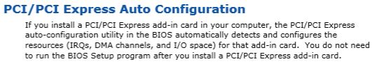
I attached the only description of mini PCIe slot in manual and the image of onboard SPI flash memory as you suggested, hope they would be helpful.
PCIe content in Manual
PCT 25VF016B SPI Flash on Intel D2700MUD
While we waiting for the order shipping and delivery, I’ll try to study the “NVME mod” you mentioned and bring some new questions soon, I hope this won’t bother you too much, please keep in touch.
Thank you very much!
Unacceptable slow for some chips is normal, some programs like ASProgrammer do that too sometimes (20+ Minutes to write). To me, that does not mean incompatible, just means "Slow to work, but does work"
CH341A and EZP2010 or EZP2013 may be same, all may use CH341A programming chip, I’m not 100% sure though and can’t find EZP specs
Thanks for image, that is knock-off SST chip - PCT not SST, but many programmers will detect as PCT since it’s meant to be a SST (knock-off) I will order one of each and see if both act same and what software works etc. but it will take 3-5 weeks to arrive
Once you can dump chip, I can do the NVME mod for you. So, it is a MiniPCIE Slot, this does change things, and what I originally mentioned may apply.
I’ll check the manual and see what I can find. Was there anything originally in this slot, if yes what was it?
I found this in manual
The board has the following add-in card connectors:
• PCI Express Full-/Half-Mini Card slot
• Conventional PCI bus connector (with riser card support for up to two PCI cards)
Note the following considerations for the Conventional PCI bus connector:
• The Conventional PCI bus connector is bus master capable.
• SMBus signals are routed to the Conventional PCI bus connector. This enables Conventional PCI bus add-in boards with SMBus support to access sensor data on the board.
The specific SMBus signals are as follows:
The SMBus clock line is connected to pin A40.
The SMBus data line is connected to pin A41.
The Conventional PCI bus connector also supports single-slot and dual-slot riser cards for use of up to two bus master PCI expansion cards. In order to support two PCI bus master expansion cards, the riser card must support the following PCI signal routing:
• Pin A11: additional 33 MHz PCI clock
• Pin B10: additional PCI Request signal (i.e., PREQ#2)
• Pin B14: additional PCI Grant signal (i.e., GNT#2)
NOTE
BIOS IRQ programming for the second PCI slot on PCI riser card:
• ID_SEL: AD20 (Device 4)
• Second PCI slot INT Mapping:
INT A# (A6) INT D# of mother board PCI slot.
INT B# (B7) INT A# of mother board PCI slot.
INT C# (A7) INT B# of mother board PCI slot.
INT D# (B8) INT C# of mother board PCI slot.
NOTE
The Conventional PCI slot on this board does not support the PCI PHOLD1 function. Due to this limitation (errata), certain PCI cards may experience performance or detection issues when DMA transfer is used as part of the PCI card operation.
And you may need fix like this for SMBUS, it may not apply, but came to mind so I’m putting here so you can further research and see if anyone had to do similar for SSD’s/controller cards etc.
http://yannickdekoeijer.blogspot.com/201…controller.html
https://gsid.in/using-old-mini-pcie-wlan…modern-laptops/ << One for laptops/miniPCIE Etc
Additional info - https://h30434.www3.hp.com/t5/Business-P…30/td-p/6109003
What is the model of the NVME you’re trying to use? I asked above, and just realized you gave info for controllers/adapters, but not for the NVME SSD itself. And, due to just now seeing this, have you tried the NVME SSD by itself, without the controller card/adapter?
Dear Master Lost_N_BIOS, I had slooowly programming experience as well, to me, that’s not a problem either, I was told that CH341 isn’t good at AAI operation which featured by 25VF series. I’ll be sharing images of the inside of those programmers when I receive them, we’ll know it by then. ![]()
The Datasheet of PCT 25VF016B can be downloaded <here>, the footer of its pages says “This product uses SuperFlash® technology licensed from Silicon Storage Technology, Inc”, it appears to be the same model by another manufacturer IMHO, like those re-branded 24C16.
The retail D2700MUD was delivered with an empty mini PCIe slot, I guess Intel meant it for a wireless adapter according to its documents.
OH! you did take a look into the manual, MUCH APPRECIATED! I didn’t mention that since the description was mainly for Conventional PCI slot, the 32-bit/33 MHz old fashion one, I could be wrong…
After reading the posts you linked, I’ve checked for the 2 SMB pins in mini PCIe pin-out definitions, they are pin#30 SMB_CLK and pin#32 SMB_DATA, however, those pins on the SSD PCB layout were left float, so… no SMBus magic for me…
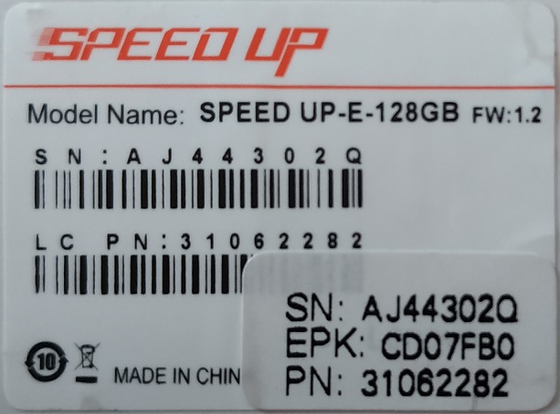
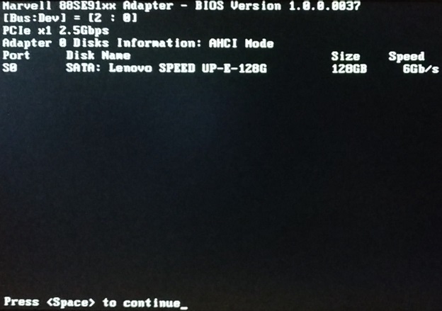
The SSD model is “Lenovo SPEED UP-E-128GB”(images attached below), although Lenovo labeled it as an mSATA SSD, it’s a PCIe SSD actually(with a dedicated SATA controller integrated) and would not work with mSATA slot, please refer <here>, I have no problem desoldering Marvell 88SE9170 SATA controller, but the SSD won’t work in mini PCIe slot without it IMHO.
Lenovo SSD Label
Lenovo SSD PCBA
I don’t think desoldering the marvell controller will help, I assume it would only cause the device to fail in all ways if that was done. Can you set storage and PCI/PCIE option rom settings in your BIOS, or do you need those settings made visible?
Maybe you need to set one or both to legacy or UEFI, along with the settings you were already changing to UEFI/Legacy. We’ll have to wait on programmer to do any of that, unless we can do it via EZH20UVE
Please download all three versions of H2OUVE from here (get v1.1 package), and run the following commands from each of the versions and see if we can get any output files
https://github.com/mikebdp2/Insider_BIOS_Tools
H2OUVE.exe -gv vars.txt
H2OUVE.exe -gs -all Setup.txt
Try those both, from all three versions of H20UVE, and leave any created txt files in place until you are done, then rename them with end of version # or something, so you know which version gave you which files.
Then upload all files in a zip for me to look over
Yes, I wasn’t sure about that PCI comment in the manual, but thought it was worth looking into since this can often refer to PCIE slots as well (which I assume may also apply to miniPCIE Too)
Does this board use Intel ME? Check BIOS main page and see if ME FW version is shown, if not then download HWINFO64 and on the large window on left side, expand motherboard and find ME area, inside that get the ME Firmware version if shown and let me know FW version
Master Lost_N_BIOS,
The SSD itself is working in AHCI mode, the option ROM displays no info about hotkeys (e.g. CTRL + M) for configuration, as for BIOS, there is no configurable PCIe option either, please check the images:
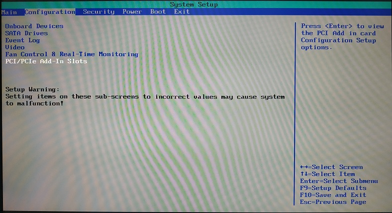
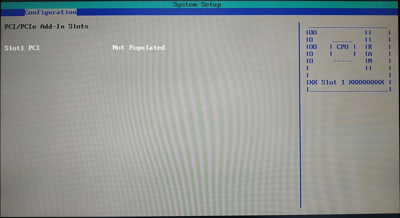
I’d like to make those settings visible for sure if possible. ![]()
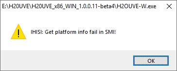
Now let’s see H2OUVE, I’ve downloaded all 3 releases from the link you provided, and here are the unexpected results:
H20UVE_x86_WIN_1.0.0.11-beta4(Windows 7 compatibility mode, with administrator privileges)
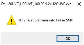
H20UVE_100.00.9.2(with administrator privileges)
H20UVE_100.00.16.08(with administrator privileges)
2
3
4
5
6
7
8
9
10
11
E:\H20UVE\H20UVE_100.00.16.08>H2OUVE.exe -gv vars.txt
Now parsing Variable Information.
Failed to get bios data!
Fail to get Variable Information.

E:\H20UVE\H20UVE_100.00.16.08>H2OUVE.exe -gs -all Setup.txt
Read Memory data failed!
Can't write BIOS Version fo File!
Read IFRPKG pointer failed!
Initialization IFR Package failed!
Fail to get SCU setting.
Since I could only chainload(from Grub2) into Windows on BIOS/Legacy mode, I think this could be the reason for no success.
Next, the HWINFO64, the BIOS appears to be a model without Intel ME, I attached the report file below.
I've received EZP2010 today, it's based on Silicon Labs C8051F340 and here is the image:
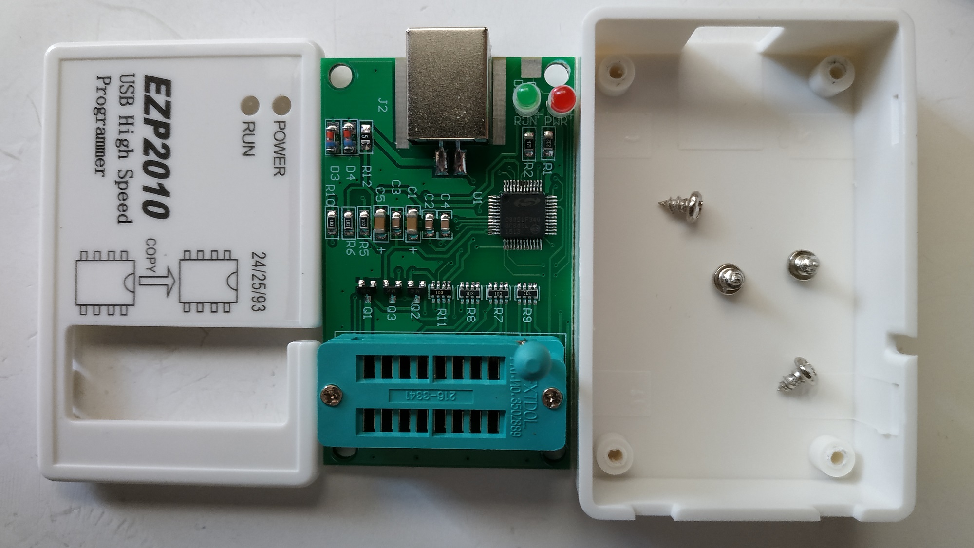
The other 2 programmers will arrive by tomorrow, please let know if you have any precautions/pre-instructions or anything else, I’ll be ready to follow your lead soon. ![]()
Intel_D2700MUD_by_HWiNFO64.zip (12.6 KB)
On the option roms, I meant BIOS settings options (not hotkeys), usually on the “Boot” BIOS page. Settings like “Storage option rom” Legacy or UEFI, Secure Boot mode, OS Type etc. These may all be hidden from you
That first image is the Marvell controller AHCI BIOS Post screen. That may be a bad sign for this, best compatibility would be if it was routed through the Intel controller, Marvell onboard motherboard controllers are terrible and limited.
Hopefully your BIOS has a passthrough mode for this port/controller, we’ll know more once I can look in a BIOS dump
On UVE app, yes that may be due to how your loading windows, not sure, since I don’t know what you meant. Please test on a direct Win7 install, no XP, and no Win8-10
HWINFO report does not help, I don’t see ME there but also never look at those, I only know to locate it within the program itself in the expanded motherboard section (Drivers will need to be installed first for it to show up, if it’s used)
But, I checked the driver download page, and do not see ME drivers listed, so you’re probably correct and it doesn’t have Intel ME.
Thanks for image on the EZP2010, good to know it’s not CH341A inside there too. Once you can send me a good BIOS dump, I bet we can make some progress.
Dear Mater Lost_N_BIOS, I’ll be attending my friend’s wedding this weekend, so the BIOS file would be a bit delayed, I am sorry for the break and inconvenience, wishing you a great weekend!
No rush from my end, have a good time at the wedding and enjoy your weekend!
Hi Master Lost_N_BIOS, I am back to normal stats, the BIOS binary file is attached, dumped and verified via CH341A from onboard PCT 25VF016B SPI flash, please take a look into the file.
I know you are helping quite a few people with their problems, so I’ll just wait in line for my turn.
As for the additional UVE and HWiNFO64 information, I’ll update those results on UEFI mode in 2 days.
Thank you as always!
Thanks for dump. But sadly, nothing I know of decompresses this correctly into a parsed BIOS, the main BIOS volume where I would do the NVME mod remains similar to how it was in the stock .bio file (little more expansion, but not enough to properly be parsed out into BIOS modules)
UEFI Mode for UVE and HWINFO etc, why that mode, mode doesn’t matter only operating system (Win7 for UVE) So, I think our only option here is to change any settings we can find, to maybe make the one mode you did have working work better/properly.
Hey, if you can flashback your original BIOS board try those tree ( A B C ) and let me know which one boot if any, you might be lucky!
else skip.
Hi Lost_N_BIOS!
Ah… that’s sad indeed, I did try some tools after learning basics here, so I know some higher level skills are necessary, I’d like to try the only option, looking forward to any modded BIOS file available.
Maybe you’ve already tried this, just saying:
There will be only 2 entries if I open Intel .BIO file with MMTool v4.5 directly, when I opened Intel .BIO file with PhoenixTool, it creates some .rom and .BIOS files within a folder named “DUMP”, then I opened some of those .BIOS files with MMTool v4.5/latest UEFITool, I see there are more entries with normal names, is this helpful?
Thank you. ![]()
BTW, I’d like to share some programmer read/write info here just for reference(SPI Flash - PCT 25VF016B, BIOS file size - 2Mbytes):
CH341A(Software v1.35) Read: less than 36,000ms     Write: less than 6min 35sec(avg 5,400Bytes/s)
EZP2010(Software v3.0) Read: less than 8,000ms      Write: less than 25,000ms
Plus, the software comes with EZP2010 is virtual machine compatible, so you can program chips by running a 32-bit VM on x64 Windows platforms, without disabling driver signature enforcement, and the CH341A’s software I am using is not virtual machine compatible.
Hi noInk, good to see you are interested in this thread! I’ve downloaded file A and B, and file C is hiding like this:

xD
Both A and B started normally, however, neither of them booted the mini PCIe SSD, it’s said "No boot device has been detected…" like before.
I’m looking forward to testing file C, I think I do need some luck. Thank you! ![]()
Enable UEFI within the BIOS option with either A or B and install the OS.
The OS installer will let you select and make the NVME bootable.
Both A an B should have NVME support.
C is pretty much your readable original BIOS.
Fixed the 404. Sorry. NP.
–
Anyway the lenovo PCB you got there is mSATA.
The BIOS PCH\SATA DXE infrastructure\driver may not support natively AHCI on that port, an option rom must be embedded by the module vendor\manufacturer or inserted within the BIOS.
What you can really do with A or B is;
either find an ultra cheap ribbon Mini PCI-E to PCI-E Express ( plus the NVME module+adapter ) or something along this passive direct approach .
.