After changing some BIOS settings, my system wouldn’t power on at all. I then tried to recover it using a CH341 programmer. I downloaded the official ASUS BIOS, removed the CAP header, converted it to a BIN file, and flashed it to the BIOS chip. Now, the system powers up (fans spin, LEDs light up, all components get power), but there is NO POST, NO Q-LED activity, and NO boot—just a black screen.
I’m also wondering if my issue could be related to the ME firmware. Is it possible that the official BIOS file I downloaded does not contain the ME region? Maybe the ME firmware on my chip is now missing or corrupted, which is why the system doesn’t POST. I’m concerned that by flashing only the BIOS region, the original (possibly damaged) ME firmware was left untouched or has become unusable.
Edit by Fernando: Thread moved into the “BIOS Problems” Forum Category and thread title shortened/customized
Should I download this 12.81 and ME, add it in FIT, and add my own OM and bios region files in EM? and build? Or is that not enough? I also tried the 2004 bios and the 2101 bios. It’s strange that there is no QLED and no feedback, it doesn’t give a picture, I don’t know what state the machine itself is in. And this Intel Management Engine (ME) Firmware Version 12.0.81.1753 (S&H)(1.5Mo)
updater is downloading, but my machine won’t start, I don’t know what to do with it?
And so far I have downloaded Intel Management Engine (ME/AMT) Firmware Version 12.0.96.2562(S&H)(1.5Mo)
this is what I added to the FIT, not Intel Management Engine (ME) Firmware Version 12.0.81.1753 (S&H)(1.5Mo)
is this a problem?
Sir… new ME fw is not the issue here, the board must be recovered and the Asus file is complete.
CSME FW update is for later operation, nothing to do with a system board recover as this model has only one IC.
Why are you messing with ME FW, FIT, making new files, etc…
FD44 Editor can be use to transfer board original data to CAP/BIN, now or later…doesnt matter.
Try other flashing apps Neo, AS, Col… dump and read back, compare…
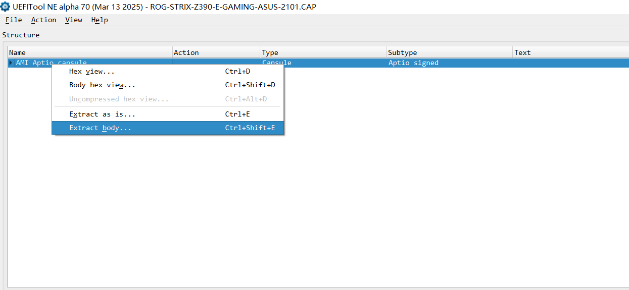
Because first I did it by converting the cap file to .rom extension with uefi tool extract body and tried to flash it, the program always runs flawlessly, but first max fan and black screen, then fans work normally, apparently everything is fine, but black screen and no post, no boot, no bios, just black nothing.
and someone wrote that then the ME part could be corrupt and that it should be changed :I’ve been dealing with this topic for a week, so I’m really stupid about it
But I’ll try the cap editor you mentioned! Thanks for the help!
Ok but in this model that ME issue doesnt arise as its part of the whole Asus data file as well a single flash IC, so if wriitng to the IC, you’re writiing all regions of Asus file including ME_region.
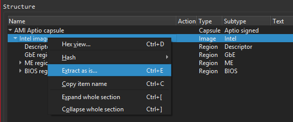
Im sure that by now you have open the CAP file and you can see all regions correct…so your doubt has really no foundation, does it?
The fan speed stabilization is usually a positive clue… no beeps no debug post leds?
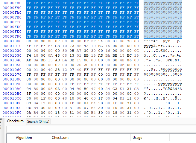
CAP to bin on Asus is very simple, besides UEFI tool (Intel image extraction), cutting with an HEX editor 0x1000, on this model, you get the same result, header removed.
if you mean red white yellow leds that indicate the post process, they haven’t been there for a while black screen it seems to be working but it’s stuck in nowhere. Now I’m trying to convert siman cap to .bin. Did someone also say that in principle it won’t work if converted to .rom?
fd44 editor doesn’t allow saving img, I think I should give some parameters which I unfortunately don’t know
I just pasted data from a dump (costumer file, not to share) into a new ready-made file… no weird messages from FD44 and data was passed/saved.
I already told you how you can get the 2 file extensions, PURE files…
We can’t pass over the acquired “experience” to users in a forum… we can only guide them a bit and some clues, no more miracles here, i think you understand it.
and i’m going to finish here, good luck.
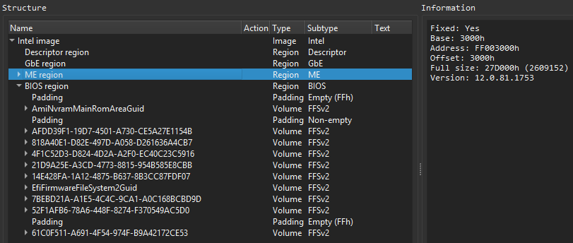
So if I don’t have a bios dump, then there’s no chance of success. I compared yours with mine in UEFI tool and all I have for ME Region is this:
Full size: 27D000h (2609152)
Version: 12.0.81.1753
Even though I download the BIOS cap file from the Asus website, it doesn’t seem to contain everything.
I understand, without the dump, that’s all the story was trash.
Wrong… the dump is only needed for original motherboard data retrival (UUID, SN, MAC)
nothing to do with getting the board to work state.
The file/capture i present, is MADE FORM THE ASUS CAP file sir…THIS IS THE FILE TO FLASH damm it, what part didnt you understood yet… or i thought you did?
The CHIP is winbond w25q128jvsq , use black CH341 and I used neoprogrammer and AS Programmer as well. Always Verified after the flash process. I don’t know about Volt, someone recommended this tool if MOBO bricked and doesn’t start.I haven’t tried this dump comparison yet, thanks for the tip!
You say that you can download a .cap file from the ASUS support page, you have to remove the header part with a UEFI tool or hex editor and save it as a .bin file and this is a full-value file and can be flashed onto the chip.
EDIT: Im not upset…but im upset as you are inconclusive about getting the simple file and flashed, do the file, share the file, share verification proof.
Im also not English native… but so far seems everyone understands me a bit…
Who knows…maybe the board has other issues besides a bios corruption…
Take the damm file, flash it, dump again the IC verify this new reading against original provided file, show us a screen if you please…
Do you even know how to compare the data of 2 files?
The Winbond W25Q128JV requires 2.7 - 3.6 V for normal operation.
The black CH341A often has 5 V going through the MISO, MOSI, CS and CLK SPI pins which can potentially damage an EEPROM that is designed for lower voltage.
There are several threads on the Win-RAID forum about issues reading/writing to the Winbond W25Q128JV with a CH341A.
You didn’t state which version of ASProgrammer you are using but according to this threadNeoprogrammer v2.2.0.10 was used successfully with a Winbond W25Q128JV.