Hello guys, first of all I’m not sure if this is the right section in which I should post, so I apologize in advance.
I have this Intel X79 motherboard, whose exact model is DX79TO. It has a strange problem, if you turn it on, it will display the POST screen, but then will go black screen with the “E7” message in the bottom right corner. It is a generic error message.
If I go to the bios, in various ways, like pressing del/F2 or using the “Back to bios” button, it will turn itself off automatically after 5-10 seconds.
And there comes the strange: if I do the bios recovery flash procedure (Similar to the Asus BIOS flashback), removing the jumper to activate it and then reinserting the jumper at the end of the procedure, it will update the bios and will not turn itself off. At this point I can click the reset button to PROPERLY BOOT into windows. And it will work perfectly, even under 24h of prime95 and even overclocked. But then, if I turn the board off, and I’m not saying if I switch off the power supply, just shutting the pc down and then trying to boot it, it won’t boot, presenting the problems I’ve already written at the beginning of this post. And the only way to make it boot will be to do once again the flashback procedure.
With that said, I noticed in the BIOS it will say “Unknown management engine Version”, so I figured I’d have to flash via an SPI programmer a new bios, or to replace the bios chip. I’m REALLY noob on both theese arguments, so I would like to ask:
since the bios chip is soldered, how am I supposed to replace it? Withourt replacing, is it possible to flash it while still on the motherboard? If yes, how? And is flashing the bios this way the only way to solve the issue?
Little note: The problem isn’t related to RAM, CPU or anything else than the MOBO. I tried various graphics cards, ram sticks, CPUs, SSDs and power supply. I tried replacing the CMOS battery. I tried moving the CMOS jumper. I tried flashing all the existing BIOS revision.
Thanks in advance, and sorry for my english ![]()
Sounds like corrupted ME region of the BIOS, thank you for your highly detailed report. ME region needs reprogrammed, that can by done by itself, or via entire BIOS flash using certain methods, but we need to check if write to ME region is possible first.
First, do you know what version ME is currently in the BIOS, what did that used to say for ME version in that BIOS area? If you are unsure, for now, lets assume 8.1 since that is ME driver version on support site.
Download this Intel System Tools package - https://mega.nz/#!CF1l1LJK!K2l6_74FPsGig…Rvp8Efj8a5drZSc
Inside the folder find MEInfo folder go into that and select the “Win” folder and open a command line from that folder location (Hold down shift, and right click on WIN folder and select run command window here).
In the command window that opens run the following command at the prompt and put image of the output in zipped folder with files mentioned below >> MEInfoWin.exe
Next, back out of those folders to main folder with all the other folders. Go to Flash Programming Tool, and inside select WIN folder again, and do the Shift+Right click, open command window here.
Run the following command >> fptw -d backup.bin
If error 26 w/ above command, run the following to see if still error 26 >> fptw -me -d me.bin
And same, also run this if first two error, this way we have all three output attempts >> fptw -desc -d desc.bin
While at command prompt from this FPT folder, also go ahead and run this command and include image of the output in the zip folder w/ above files >> fptw -i
Put all three files and the images from the above into a zip folder and upload to any free file host and post a link here. Sendspace.com is a good free host, if you aren’t familiar with any, or any other you know of is fine too
All of that is to see if you are locked out of writing to the ME region of the BIOS, if you are then probably best to get the programmer below so we can fix. If you are not, then we can fix by reflashing the ME region.
There are other ways to unlock ME to write to, but it involves shorting some board pins out, or possibly an EFI Boot method I can link you to but have never personally used Method Here
Shorting method is outlined here - [Guide] Unlock Intel Flash Descriptor Read/Write Access Permissions for SPI Servicing
I checked stock BIOS from download, and it usually matches what the board already has locked in flash descriptor, so I assume we’ll see the following from your two above image outputs and you’ll get some errors with fptw commands 1+2 above, since flash descriptor has FD locked from write and ME locked at read/write.
Confirming the above is true can also be done by adding this command to the 3 above, this will backup “BIOS Region” only, which is unlocked for read/write, it should complete without error
fptw -bios -d biosrgbk.bin
This all means you will need to use one of the mentioned solutions, try EFI unlock method, shorting pins, or order and wait on flash programmer
If it comes to this, it is possible to reprogram the board while the BIOS is soldered to the board, and it’s cheap tools. So you could go ahead and order now if you wanted, since it takes 2-3+ weeks to get, unless you pay more to a local seller.
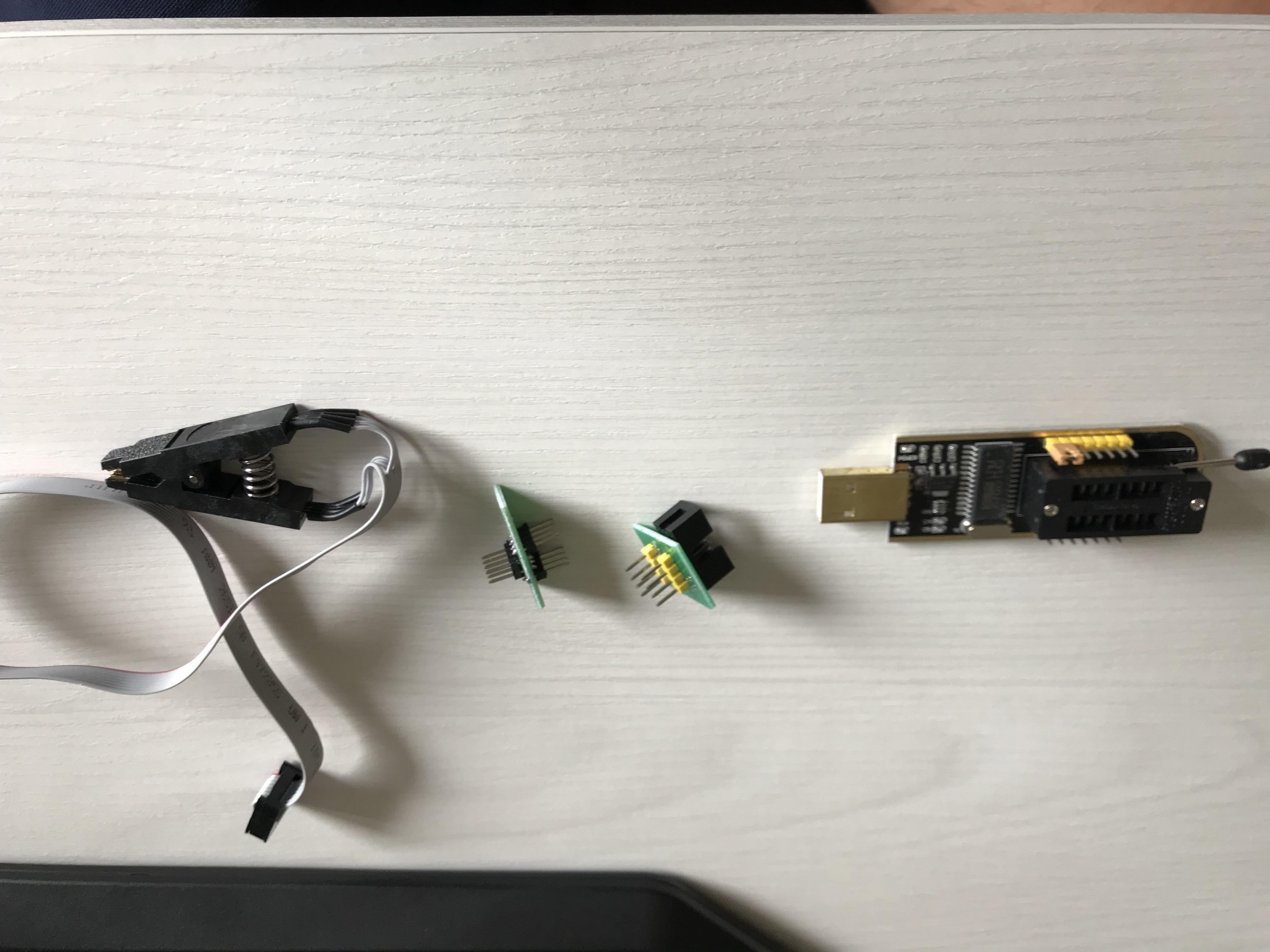
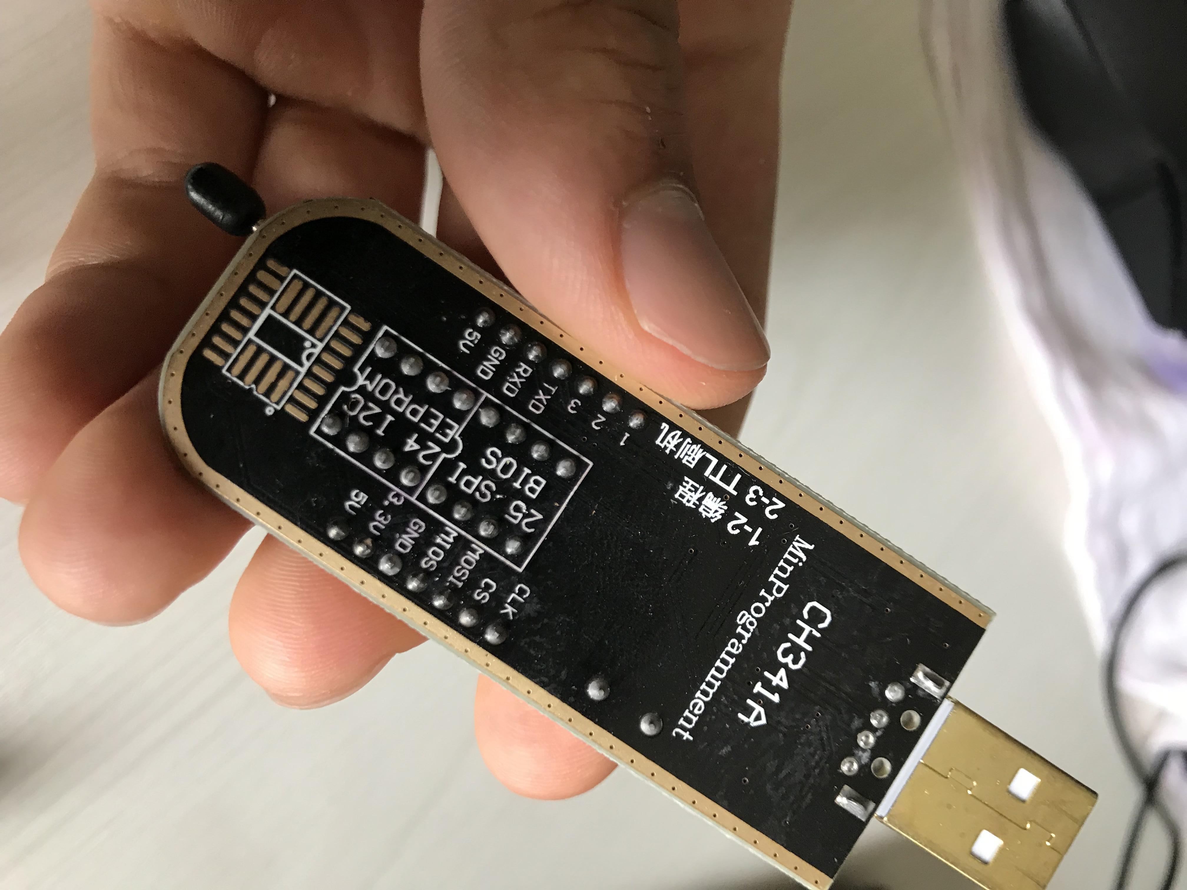
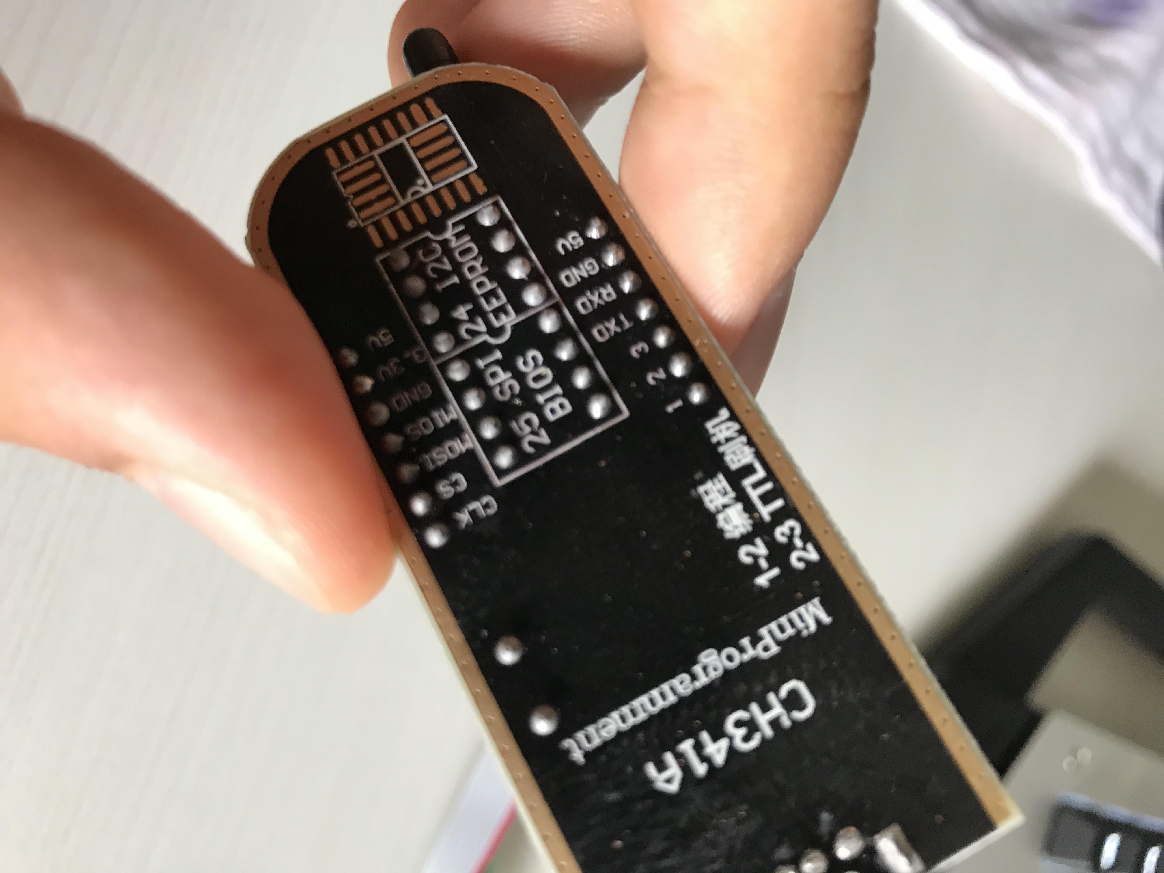
You need USB flash programmer CH341A
https://www.ebay.com/itm/263458010112 - Choose “Blue” model, if you get from another seller don’t get black/gold, no black/gold from this seller either, you want green or blue version
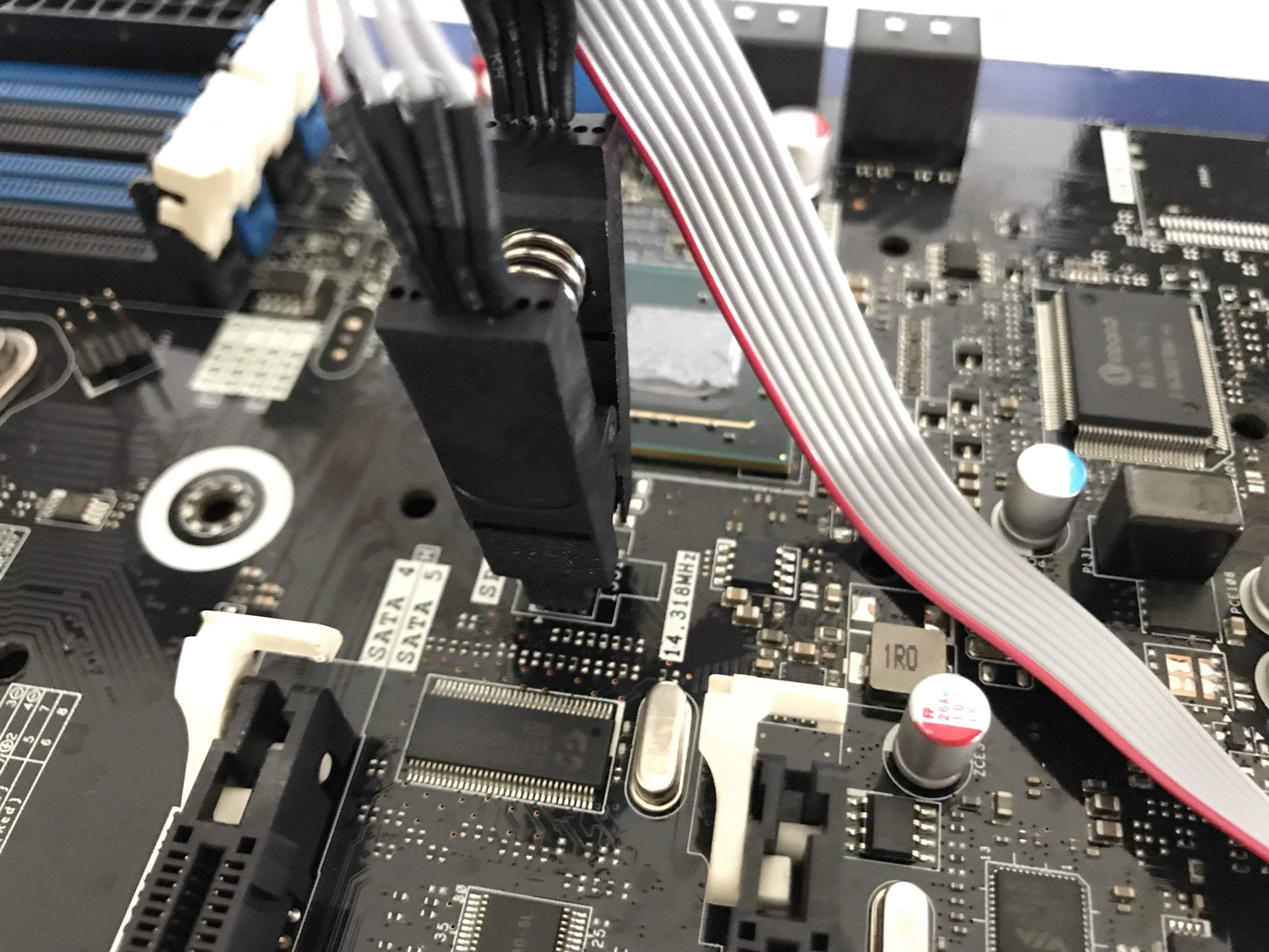
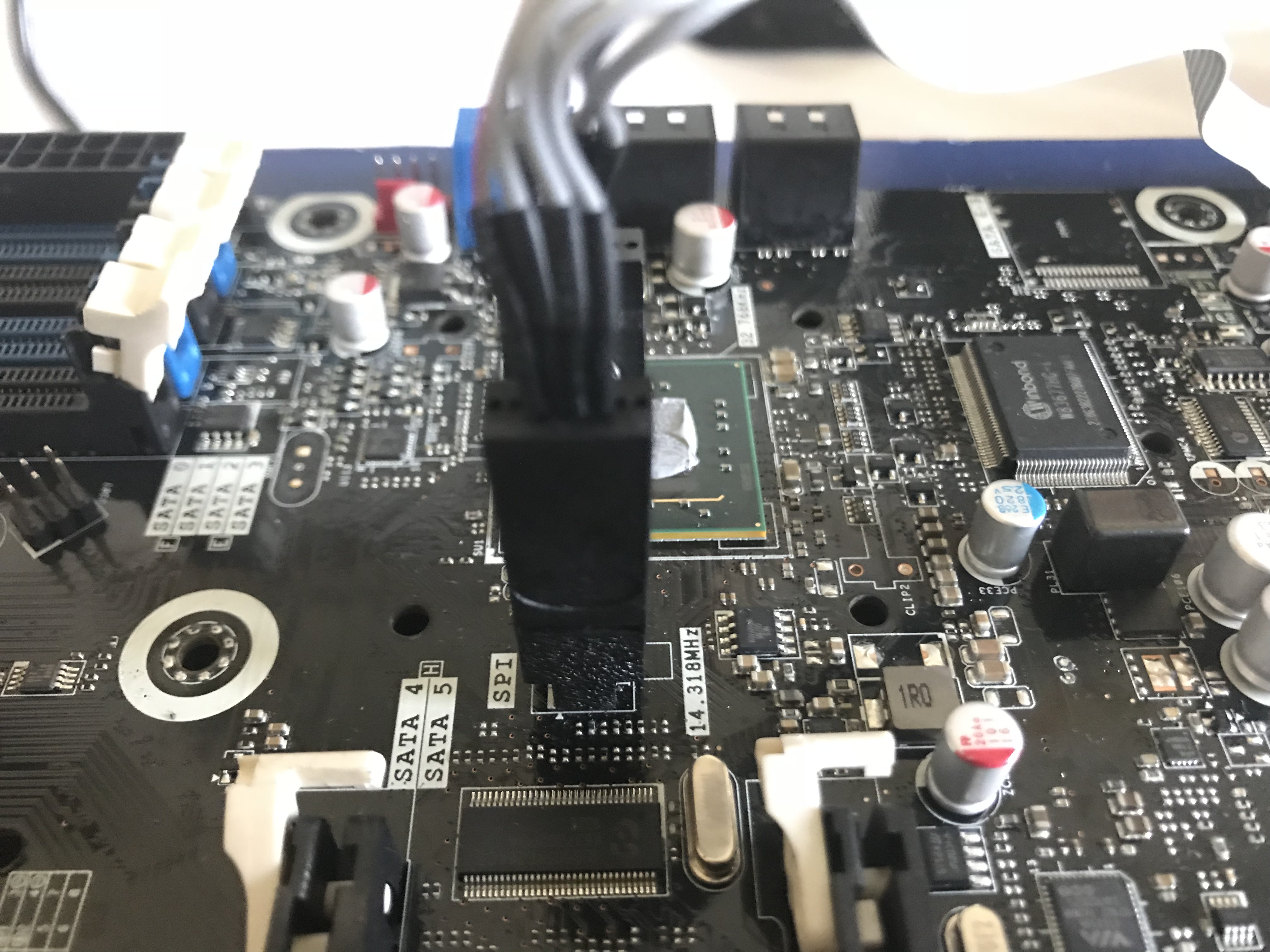
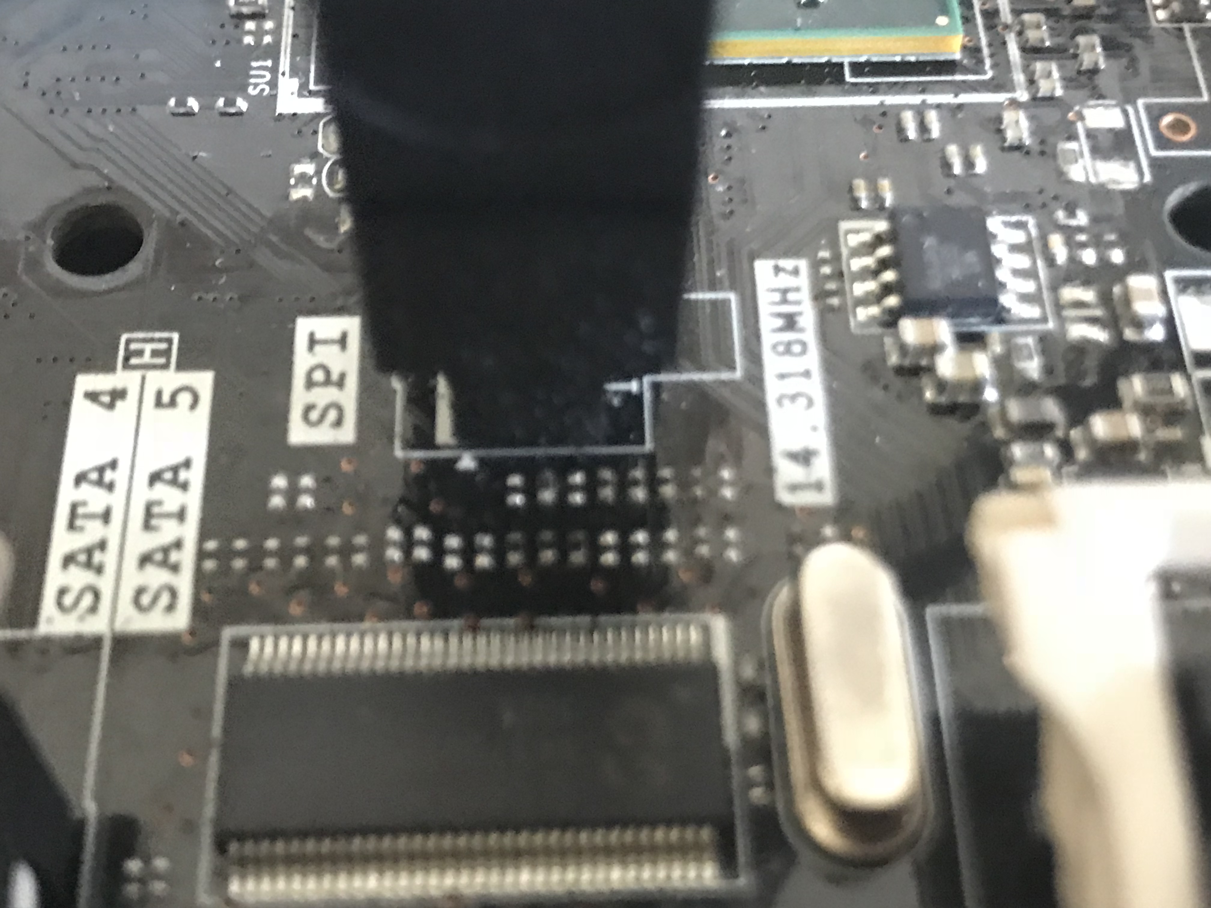
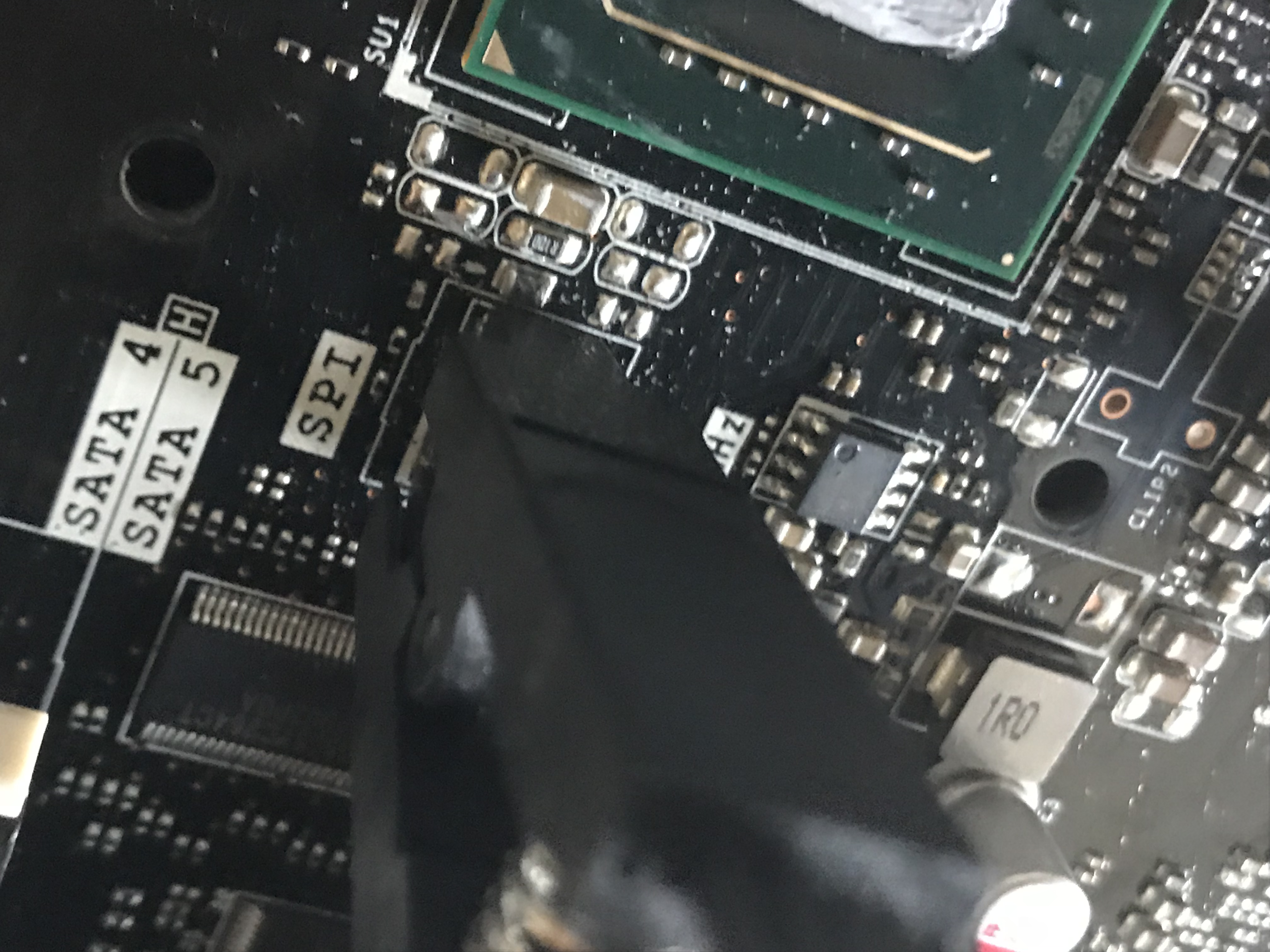
Since your BIOS is soldered to the board, it’s beside top left corner of the SB heatsink (SPI label) if you weren’t sure, grab one of these too
https://www.ebay.com/itm/263708580560
Due to the SB heatsink location, you might need to remove that in order to use the clips, not sure but it looks like it will be a tight fit.
First, thanks a lot. I wasn’t expecting such a detailed and well explained guide. I ordered 2 weeks ago the programmer, I already have the clips and I should receive the CH341A itself in the next two days. Since in order to verify if I am able to flash the ME without programmer I would have to go into the trouble of half an hour to make the board start and I would need to setup a quick test bed, I prefer to flash via programmer directly. I see you are really experienced in this kind of thing, could you explain me what I will have to do with the programmer once I have it? I read the guide on this site but if you have time to explain me again it would help a lot. Thanks again and sorry if I’m late. Have a good day!
You’re welcome! Once your programmer arrives and you get it all setup, the first thing you must do and make sure is done 100% proper before writing to the chip is to find a working software version for your setup and get a verfified backup made. That way if anything goes wrong you wont loose your boards details (UUID, serial, LAN MAC ID etc)
You may need to try several versions of the software until you find one that works correctly for your BIOS chip. Sometimes older is better, sometimes latest version is best. Sometimes you can pick exact match to you chip, other times close match works better than exact. So you may have to play around with that a little bit first, until you can get a verified backup.
To get verified backup connect the programmer to the chip and click identify once it says connected. then pick either exact match to your current BIOS chip, or close enough match (Like last 3-4 digits can be left off sometimes, example instead of W26Q64FVSIG you may only need W26Q64)
Click read, then once that is done click verify. If it says buffer/main memory and chip match 100% (may not be exact wording, but similar to that) then this is verified, click save and then put two copies of this file somewhere for safe keeping and do not edit those. When you need to edit one, copy it to another folder and then edit there, that way your backup stays safe.
Here is package of several versions of the software, and driver, install the driver first then you can test all the software versions once your programmer arrives. I always start by trying to get latest version to work properly with problem system BIOS first
https://www.sendspace.com/file/gtcmvd
Then upload copy of your verified BIOS backup here and I can fix ME region for you and send back for you to program to your chip with the write function. When I do that, I can also update the CPU microcodes for you if you want, let me know.
And yes, this may possibly be fixed without programmer, but not easily, and as you mentioned you would need to setup the board and do some of the testing I mentioned.
Since you have programmer on the way you can not do that if you want, but you’ll want to get the board setup eventually so you can test functionality once you reprogram.
Okay, there I am. I couldn’t find exactly "Identify" but I had "Chip Search" which made me look for the ID I needed, and it matched perfectly, if what I had to search was the ID that appeared under "name" in the left side of the program. Making the board working is moe than enough for me, if you have time to update microcodes I would love to, but you already helped mea lo mate. I wait for the fixed version of the bios, could you explain me what will I have to do in order to flash it once you sent it to me? Thanks again, see you soon!
https://www.sendspace.com/file/cog7u1
Microcode updating is easy for me, so no problem on that! So this BIOS backup verified 100% for you, match memory/buffer and chip? If yes, great, thank you and I will have update BIOS for you soon to program back onto the chip.
Will probably take me until tonight, sorry I am leaving shortly and wont be back until later tonight (15+ hours from now)
@ItxLeo - *Edit * this is not valid backup, please keep trying until you get it to say 100% match chip and memory/main buffer. Read, then verify, that is all until you see it says 100% match after verify, then you hit save. If you don’t get verify, try another software version.
This is blank file, 100% FFFFFFFFFF open in hex editor you will see what I mean.
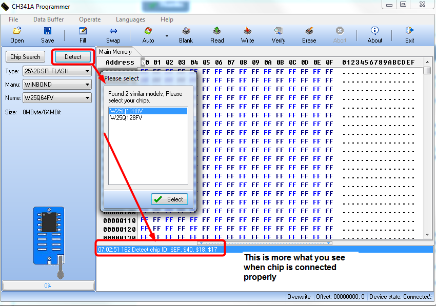
There is “Detect” chip, right beside “Search” you don’t want to use search, although you can, you want to use detect, then pick from it’s choices when they pop out to you.
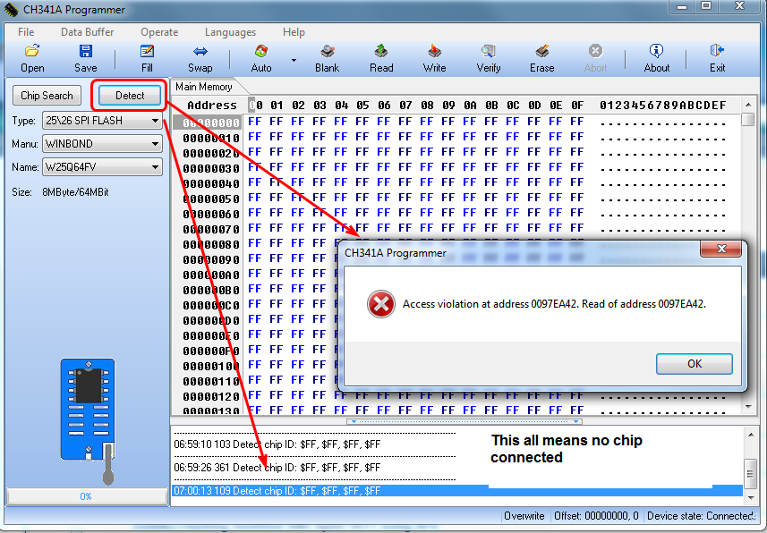
If you cannot press the detect button, then the programmer is not hooked up properly (ie not connected, you will see either connected or not connected in the bottom corner)
But really that is only for the USB plugged in on the programmer or not, see below for actual “is the chip connecting properly or not” examples
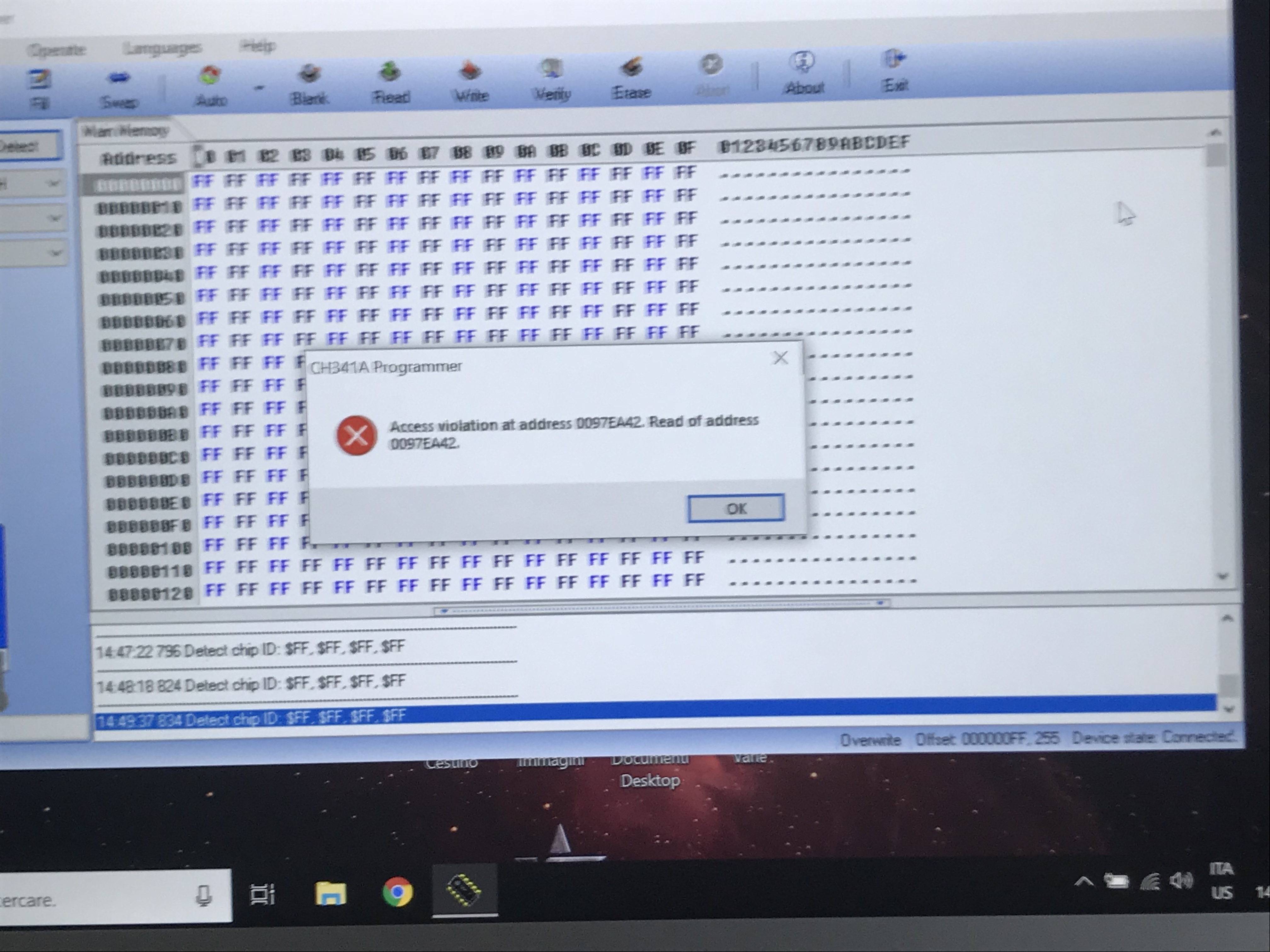
And if it’s not detecting the chip you will get access violation usually
This either means cable backwards, PCB backwards into the programmer, or both ect, check all cable and pin orientations.
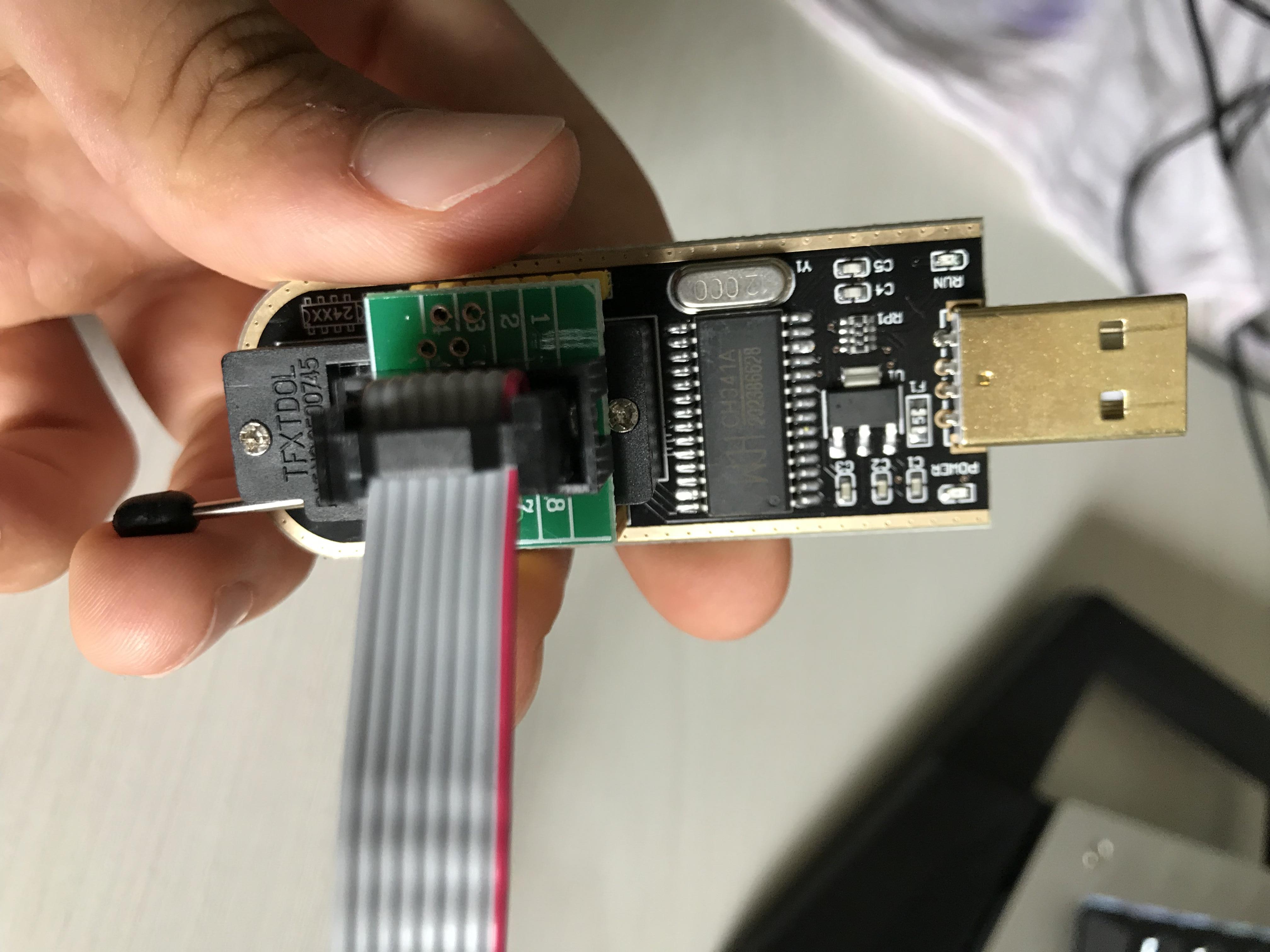
Red wire in the gray bundle goes towards pin #1 on the PCB into Pin #1 on the programmer, and then red wire goes to Pin#1 on the BIOS chip on the board
There’s usually a little circle or dot on the Pin #1 corner of the BIOS chip, also a white triangle on the board right at pin #1 too.
Watch some videos on using CH341A with motherboard on youtube if you need too, that may help easier than me trying to explain.
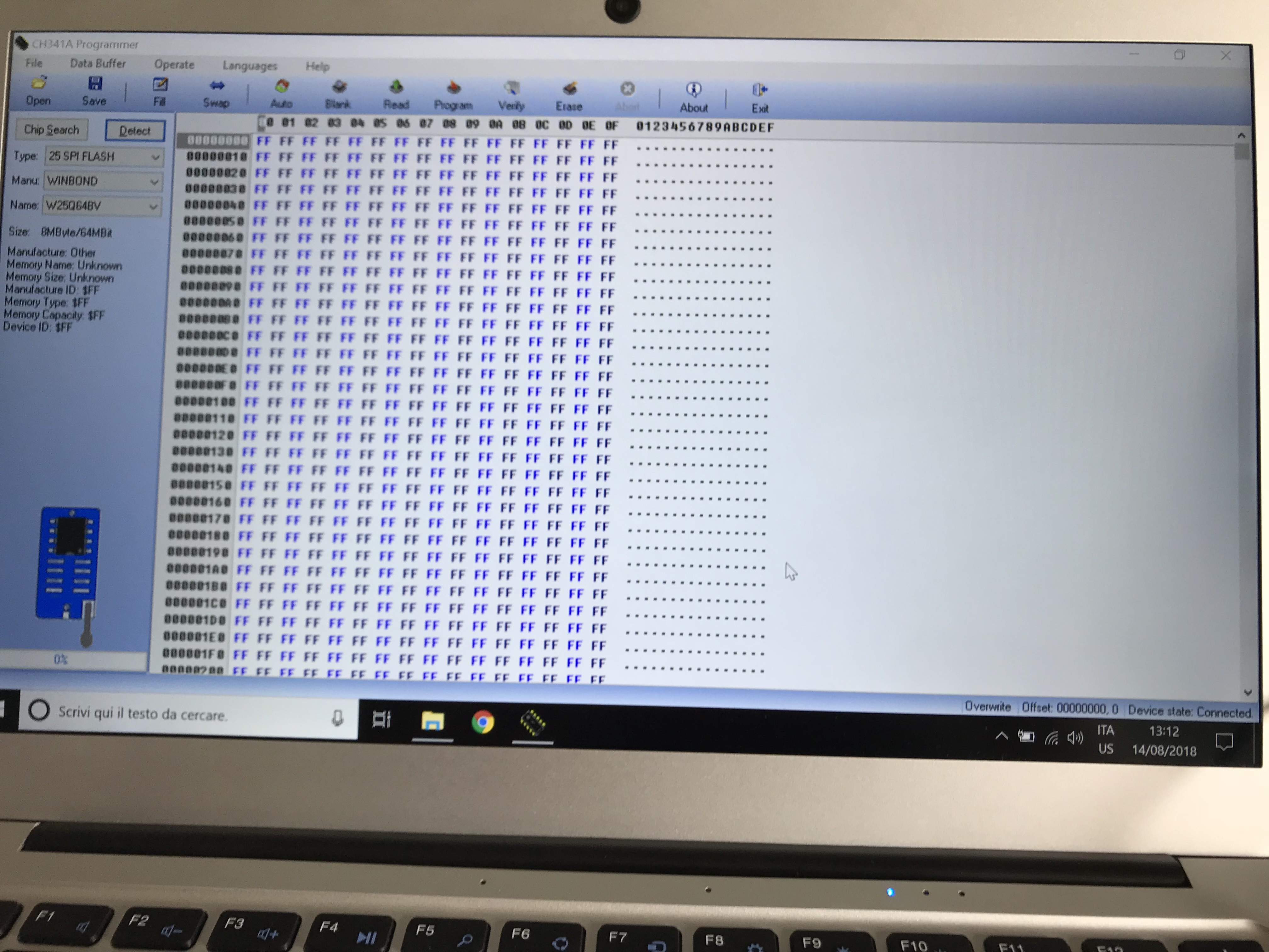
And here’s how it looked when you have chip connected properly, and hit detect. See choice menu pops up, and correct chip ID info shows on bottom area
To program back is just as easy, open the software and ID the chip, then choose write and it will let you browse to the file you want to write, and that is all let it write and verify then you are done.
Since this is an ME fix, once you write the new BIOS to the board, unplug the power supply and remove the CMOS batter for 1+ minute, during that time you can also press and hold the power on button or short the power on pins for 10-15 seconds.
This ensures the ME state is cleared and reset due to no power for 1+ minute.
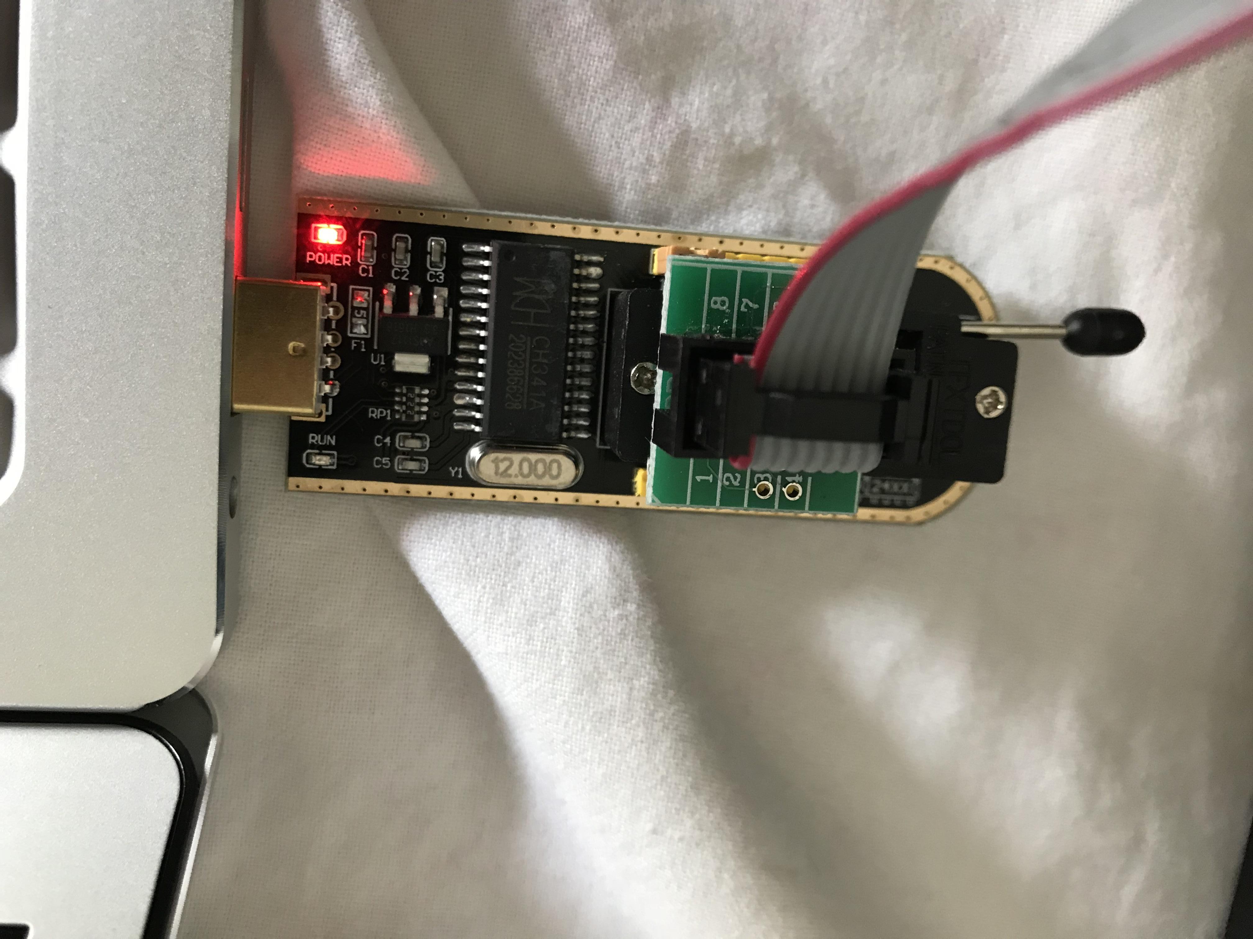
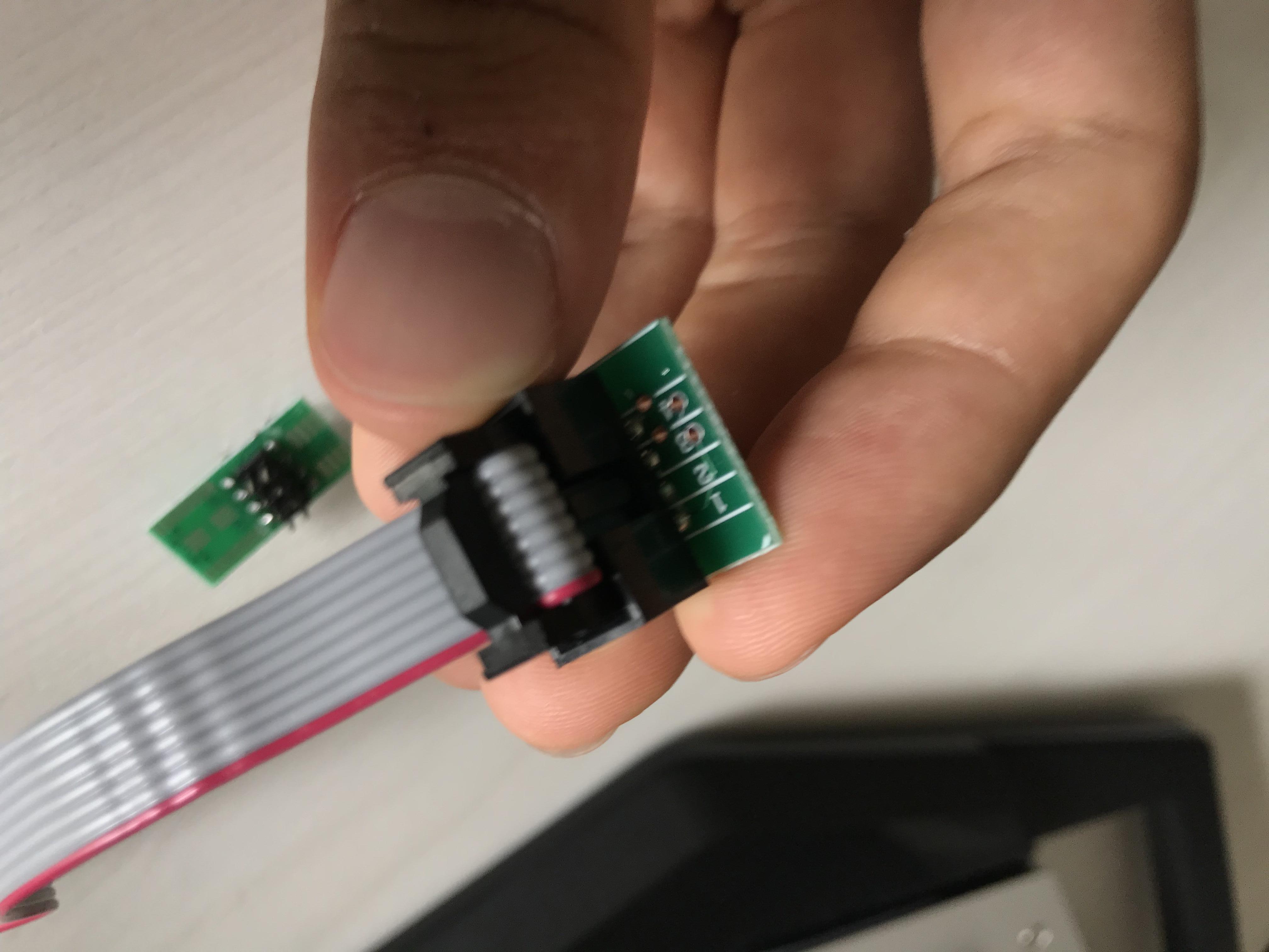
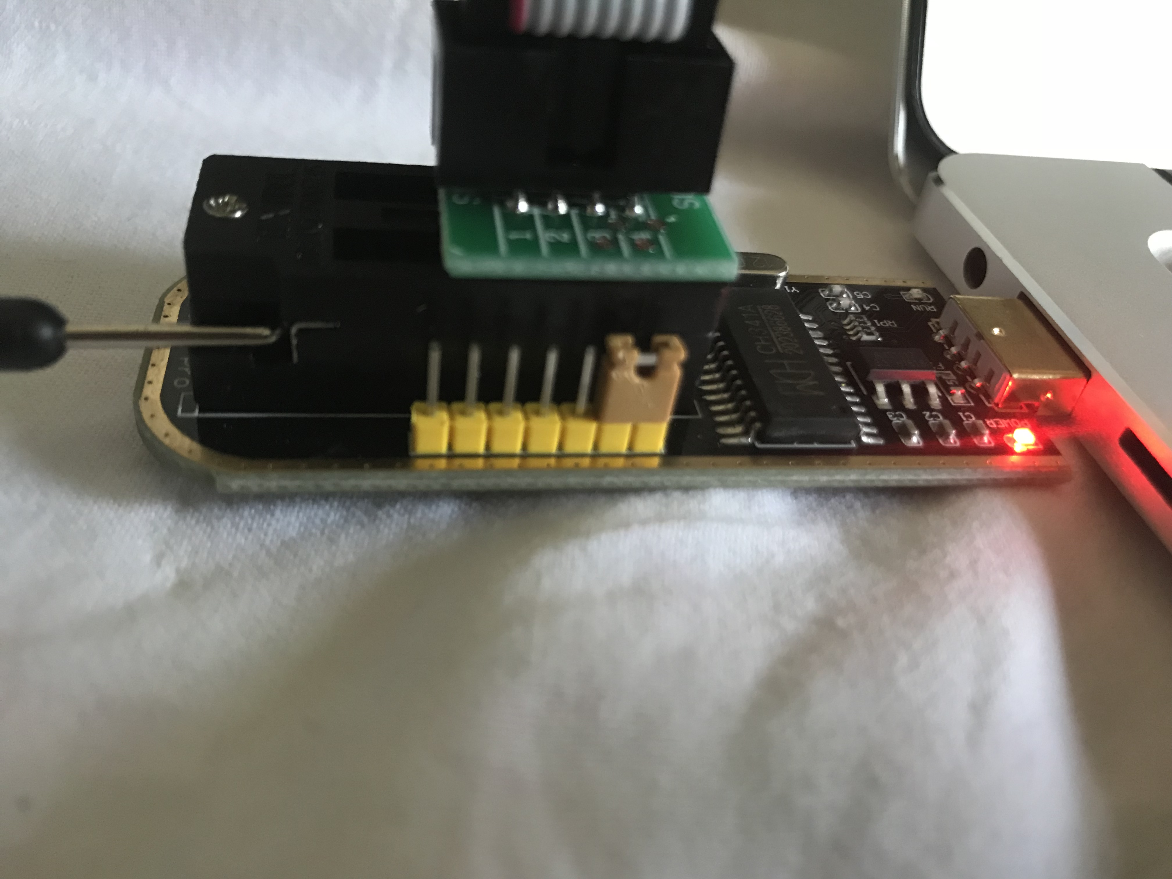
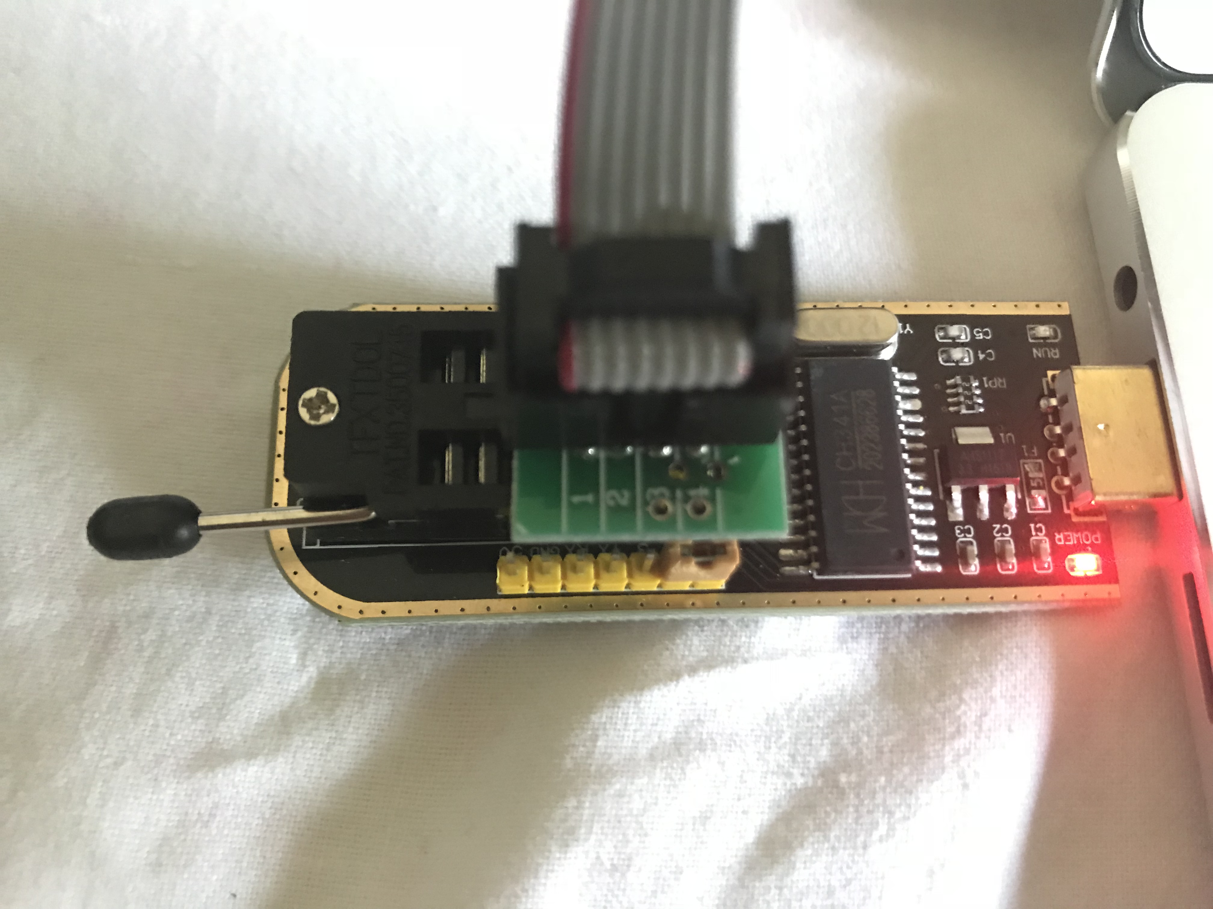
That’s my situation. I’m not sure if it is hooked up properly but I can’t make the “1” of the PCB going on top the “1” of the programmer.
Okay, sorry for the double post but I imagine the problem is in how i hooked it up. I will attach pics of what I have, so that you can tell me if I am right. Oh, during all this time I had the board unplugged and without CMOS battery. Is it okay?
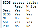
Yes, that is the issue then, I see all FF in your chip detected as section. For the cable end on the motherboard, I can’t quite see it clearly, but it looks like you have the red wire going to the pin 1 corner of the chip with the little white triangle on the motherboard PCB itself, correct? If yes, that is correct.
You have the red wire going into the little green PCB correctly, at pin #1.
The green PCB, connected into the programmer is at the correct slot (Inner-most set of pins, towards USB connection), but it is in the slot backwards.
Rotate the green PCB where it connects to the programmer, so that the #1 pin on the PCB is diagonal from where it is now, rotating 180 degrees so pin #1 on PCB and the red wire is on the lever side but still in the same slot you have it in now (inner socket)
Those numbers on the back of the programmer are for the pins along the side, nothing to do with the flash rom slot pins.
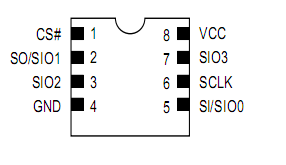
Here is example of BIOS chip, same as you see on the back of the programmer, see where pin one is on example.
On the flash rom socket side, this pin#1 is 2-3 pins above where you have the yellow jumper (Almost right above "RXD" on the backside)
And yes, OK with board unplugged and no CMOS battery, that means ME will be all reset state and ready once you reprogram BIOS.
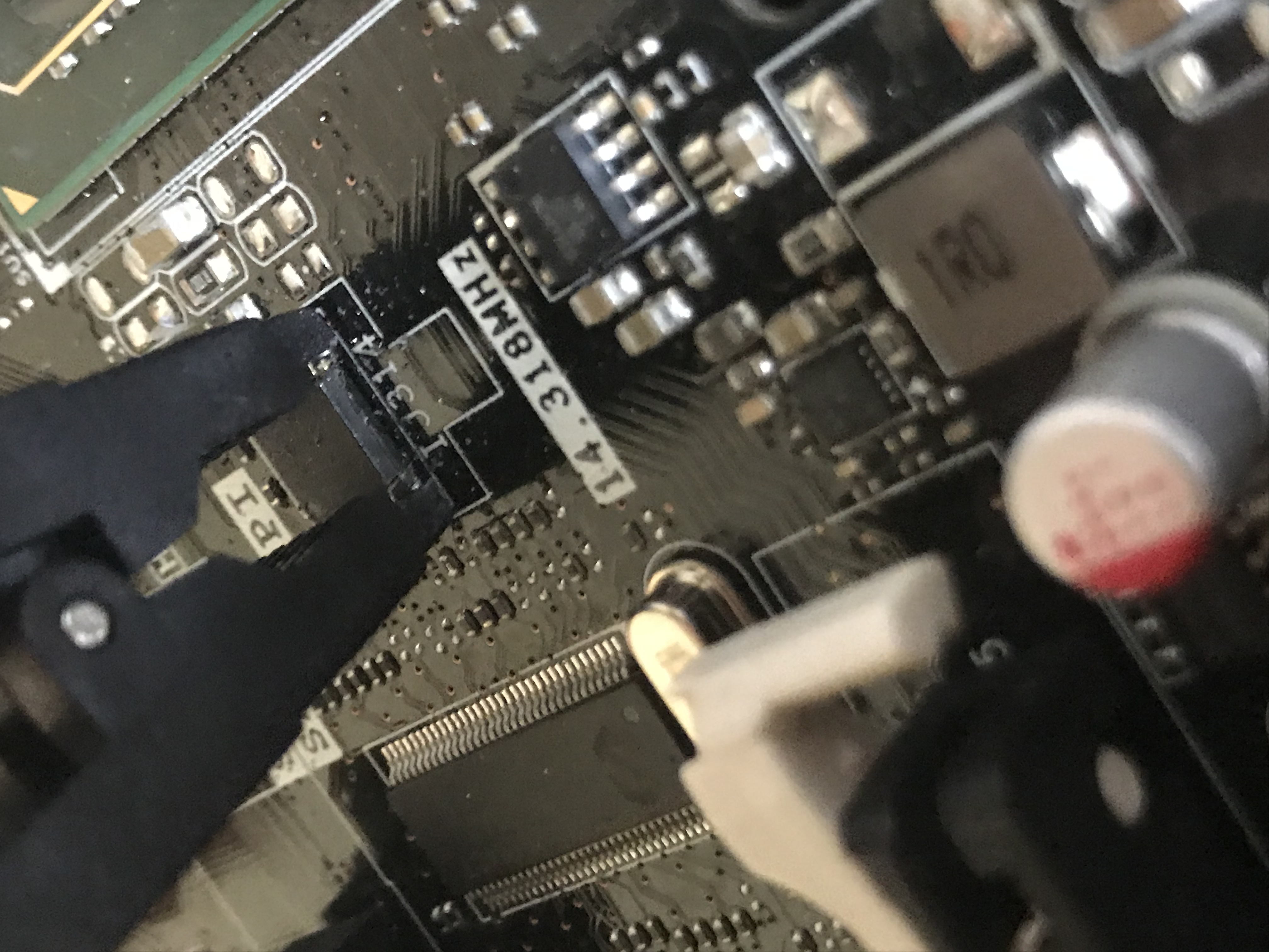
Okay, that’s how I have it now. I still get the access violation. This time I think it is because I’m not hooking up the clip properly to the bios chip itself, because of some capacitors that make it a tight fit. Do you think it is because of it? Any suggestion?
Please smaller images, thanks  - 1000-1200px OK - next time, if needed I mean
I cannot tell, if red wire at motherboard is matched up to the pin 1 white triangle, if it is OK, that is good and we don’t need to worry about that anymore.
Everything looks good. Try reseating everything again carefully to make sure it’s connecting and not shorting, especially at the motherboard pins/clip area.
I find it’s easiest to hold pins open over the chip, connect one side by touching it into place, and then slowly let go of other side so it clamps down into it’s place
In the programmer, where you connect the PCB, you are using only the last set of 4/8 inside correct? Making sure, it has to be in those last inner pin set of 4/8, can’t be some pins in there and some pins in the other 4/8 slot.
If all else fails leave it connected and try all other versions of the software and see if they all give the same error. If they do, put back in CMOS batter and see if that changes anything, if not, connect the power supply 24 pin and 8 pin and see if that changes anything (Don’t power on board, just connect power)
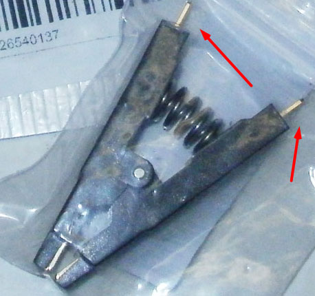
Quick update, after spending around 5 hours trying to figure out what was wrong I see that one of the cables going inside the clip wasn’t making contact properly. I tried fixing it but nothing to do. I ordered in another clip, I will have it for saturday.
That sucks, hopefully they will send you refund! Did you notice, the cables don’t go inside the chip, there is pins that come out from the clip and cables simply slide over them?
Yeah I got the refund…
I’m also having troubles with the 6 core coffee lake mod on Z170, I see you are really experienced in this kind of thing, until we wait for the clip could you give me a hand in that? [GUIDE] Coffee Lake CPUs on Skylake and Kaby Lake motherboards (30)
Good they refunded you without hassles, and hope your new cable arrives soon!
I can do that entire mod, but I have no experience with using it personally. Do you need it all done, or are you stuck on a certain part of the mod process?
If you need it all done, please give me all info.
1. Link to BIOS you want modified, + dump of your current BIOS if you have.
2. ME version you want used and if you know from research if you need chipset changed or not.
3. Which CPU microcodes do you want put into the BIOS, and which are you OK with removing if you can only keep one older microcode.
Thanks mate, in the end I managed to do it in my own. I was stuck because I didn’t change the SKU but a guy helped me ![]()
Now the only problem I have with that project is I can’t change the multiplier for all 6 cores but just for 4 of them, but I kinda got around it via BCLK overclocking, achieving a 4.75Ghz oc with 1.225 Vcore, pretty decent in my opinion. If you know how to change multi via bios it would be great but I think it is kinda difficoult because it should require specialized tools.
Anyway, I got the replacement of my programmer+clip for the X79 board, so in the next hours I’ll try again to extract the bios. I will keep you updated!
EDIT
I hooked all up, no success at all. It keep giving me access violation.
Connected the power supply at the motherboard. Now it’s even stranger. Sometimes it let me choose what chip I do have after pressing detect, but after the I have chosen, it gives me access violation.
If you haven’t any ideas on what I could do to resolve wioth the SPI I’m good with setting up a test bench and flashing it via software. If I could flash the bios normally, it would resolve, I think. Because during the flashback process it does not restore the ME, but during the normal flash it does. The problem is I cannot dio the normal flash since the board need to restart and my problem is if the board restarts then it shut off. If I could force flash it via DOS I think I could get around it, but I don’t know how to do. Anyway, SPI flashing would be the best option… But I’m managing to, I don’t know why…ù
EDIT PT.2 I’ve been messing around with it for a few hours, now I keep getting the chip detected, but only in the versions of the program which automatically select the name of the chip. In the one that makes me choose I still get access violation.
I can read the bios but I only see FF in the code of it. Anyway, on the left I Have theese informations:
Manufacture ID $EF
Memory Type $40
Memory Capacity $17
Device ID $16
I wonder if it is because the format of the bios is strange. It isn’t .rom or .bin
It is .BIO
Which is also why I can’t use afudos to flash it. I tried opening the BIOS file downloaded from the intel website in the programmer and some version of the software tells me the BIOS file is too long for the programmer. What a mess!
I’ll wait for your help, since I don’t have any more ideas about what to do
EDIT once again
I managed to read and verify one time, not sure if it is good but yeah, there we are. https://www.sendspace.com/file/uoc4sf
Ohh, cool you got it sorted out already then! I know they fixed that core count and HT issue on another thread, did you see that one? I think this is the one, but maybe that’s only HT - [GUIDE] Fixing HT for Coffee Lake CPUs on Skylake and Kaby Lake motherboards (Z170, Z270)
Are you trying different software versions too during all these issues? Try 1.31(1.4), in this package if you don’t have already from me - https://www.sendspace.com/file/gtcmvd
There is no way to force flash due to the FD locks, ME would never get written no matter what. Send new images of how you have it all setup again, in case something wrong still.
So, progress? You don’t have to match chip exactly always, sometimes even close or not same but close is best, and sometimes picking exact even causes issues. For example, chip might be W26Q64FVSIG, but choosing W26Q64 is fine/best or even choosing W26Q6BV works and exact does not or W26Q64FV does not.
Read the BIOS chip with light and magnifying glass if needed, and let me know full exact model of the chip and I’ll give you a few example models to use instead of exact match
The only thing that is .BIO format is a BIOS from Intel downloads, what is on your chip is rom/bin. .BIO files are not used for any of this, do not look at them with anything in regards to this, they do not apply
I’ll check your dump file linked, hopefully you got it! If It’s bad or all blank I will edit this and update, if not I will fix BIOS issue and have you new BIOS to program later tonight.
Edit * Dump is bad and not valid at all, keep at it you’ll figure it out shortly.
Put that jumper you mentioned on first post back to default position now, since recovery was not working no need to have that enabled.
And this may be causing issues now too.
Which CH341A did you use? Some of them didnt work at all, they use wrong 27Mhz crystal instead of correcf 12Mhz crystal.
I have CH341A in different colors. Black CH341A is able to read data via test clip, my green CH341A isnt able to read via testclip. But both of them read the chip correct if it´s put in the zif socket.
So best is to try to read another chip and take a look if you can read data. If yes then maybe the current is to low to power up some parts of the board.
He’s got the black one you like images on page one. I think maybe just wrong chip selection, or software version and combo of that and wrong chip selected
Ok, then just take a look at the software/chip selection or the crystal. I found some people complaining about wrong crystal with 27mhz.