Sorry to keep hammering this, but I need to clarify…
as I understand it, the .BIO files will not work with any tools. And a .BIN dump of my BIOS chip should work with Phoenixtool and might work with the other tools.
…is that correct?
And Phoenixtool is capable of replacing the IRST OROM with a TRIM-modded v11.2.0.1527 in the .BIN dump? I don’t really care which tool I have to use, just as long as it works and I can find instructions showing me how to do it.
I’m just trying to confirm all this information because it’s looking more and more like I’m going to need to desolder my bios chip and I want to make sure everything else is gonna work before I commit.
@gyrator :
Since I never had an Intel mainboard and don’t have any own experience with the modification of an Intel BIOS, I cannot help you.
AFAIK the Phoenixtool works with Intel EFI BIOSes, but I am not sure about it.
Hi Gyrator
I absolutely encourage you to desolder the bios chip, solder a socket, and purchase some extra bios chips for your DX58SO. If you wreck something, you can then recover.
(I used this - 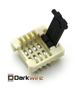 )
)
If you then dump a .bin using a ch341a, you can modify that in UEFITOOL. It’s more complicated than other mainboard vendors to modify an Intel bios, but it is possible.
The .bio will also open in UEFITOOL, and you can view its structure. Modifying the generic .bio for your board is useless for your purposes, however.
@gyrator
Nah, don’t. DON’T DESOLDER!!:X
Unless you can, after few try, rightly clip the “probe” there no way to make anything out the binary.
It require know-how, or, dunno, help by someone dealing with it regularly.
Desoldering the chip doesn’t make sense since you are in possession of one test clip.
Like I said on another topic: I personally use either one soic8 to dip8 test (clamp) clip or the IC socket directly ( situational choice ) since mine board has the clamshell.
I hear you about the socket, and if I was tinkering with this thing regularly I absolutely would but this is a one time thing. Intel hasn’t released an updated bios for the DX58SO in 4.5 years and won’t be releasing any more. The only thing I want is a modded IRST BIOS to support TRIM in RAID0. If I can pull that off I’ll never need to flash/reprogram this thing again. If I can successfully desolder the current chip and solder the socket to the board I can just as easily solder the chip back in place. Like I said, once this is modded I’ll never touch it again.
You say it is “more complicated than other mainboard vendors to modify an Intel bios, but it is possible”. Are there instructions anywhere for using UEFITool v0.22.1 to mod a dumped Intel BIOS?
Don’t desolder? Or don’t mod. I’m getting conflicting message, is it possible to replace the IRST OROM in a dumped Intel bios or not?
Mine is not in a clamshell and I didn’t have any luck with the SOIC8 clip.
I don’t understand anything you said in the last sentence. As I’ve been told, if the worst happens and the modded-bios bricks, I could always write the original dumped bios back to the chip and everything should be fine (assuming I get the test clip working or desolder the chip).
@gyrator
Like I said on PM
Right now all I can do is update the microcode for it.
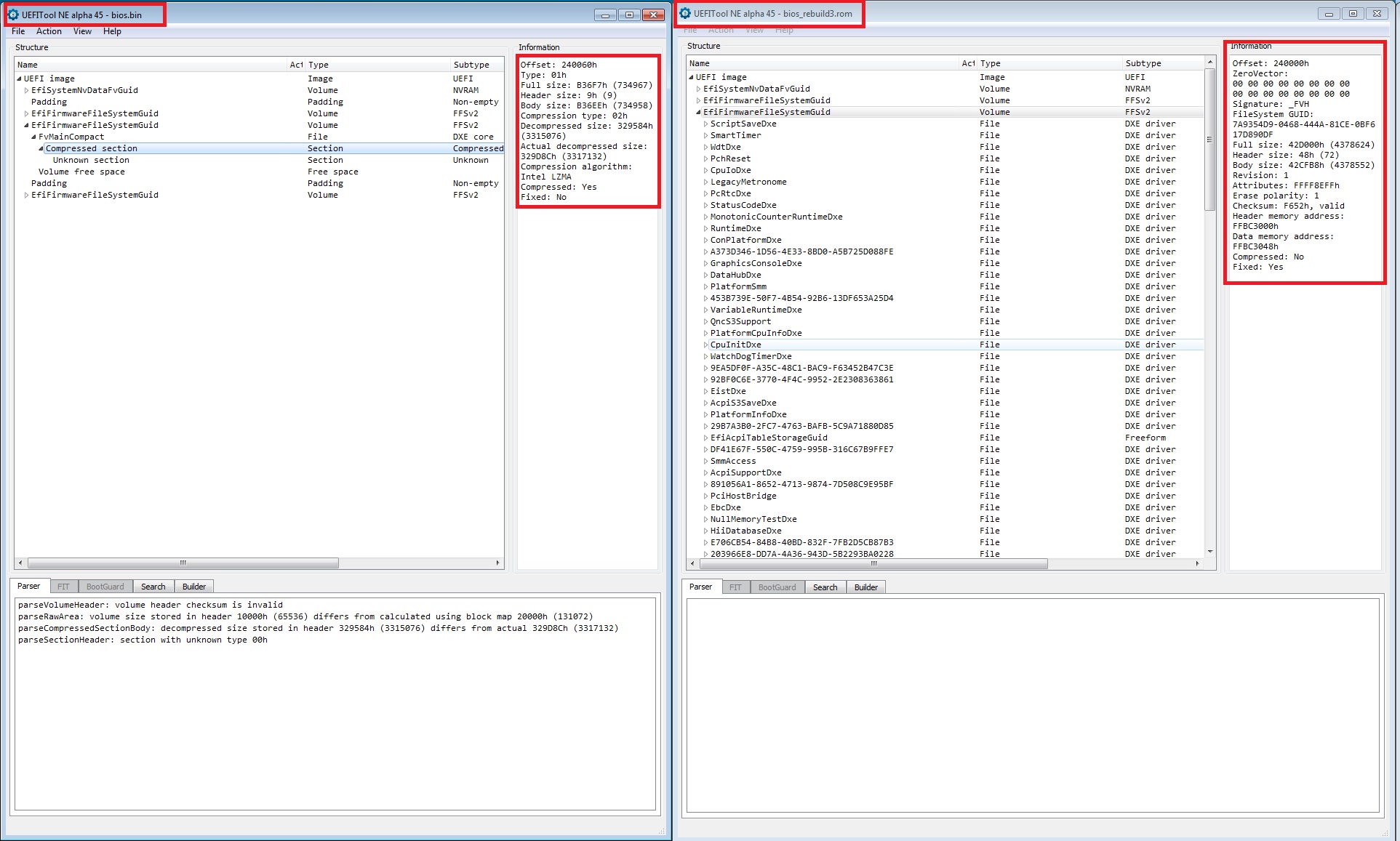
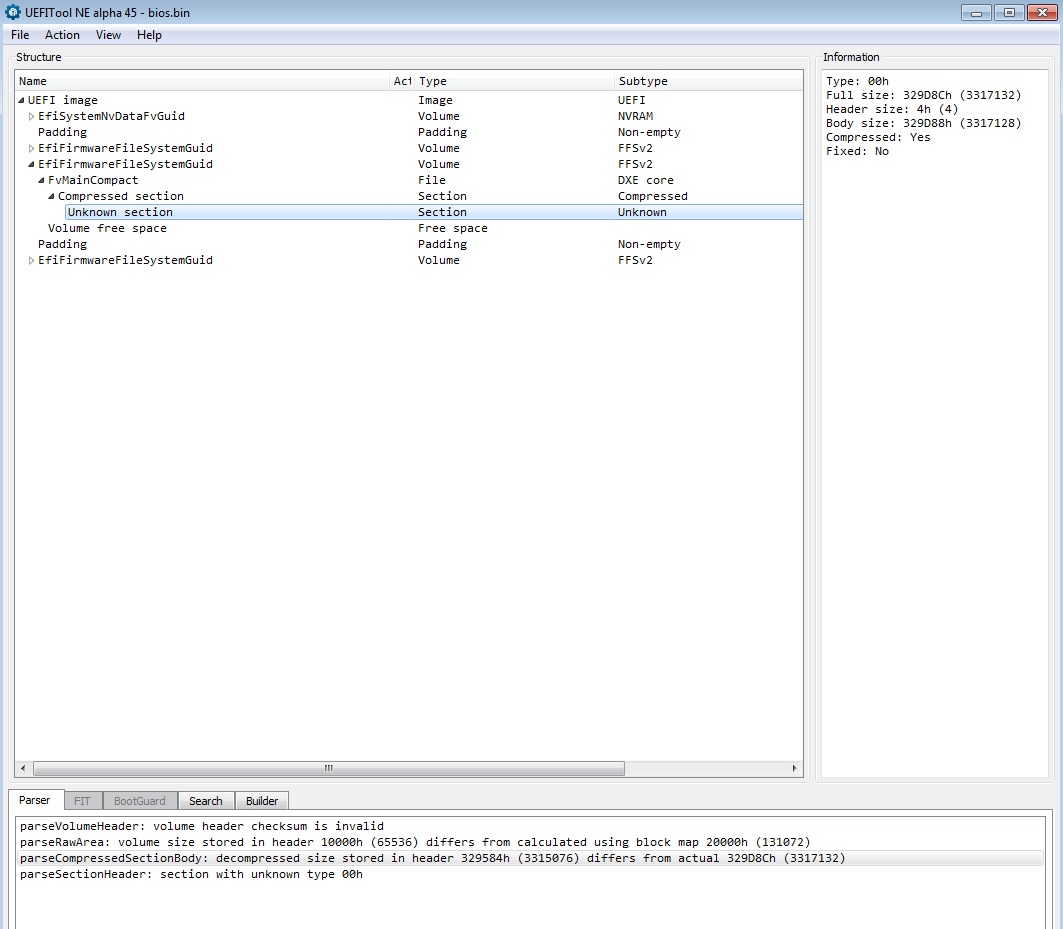
I’m able to rebuild any EFI volume with different free space.
Issue is so far the main firmware. There seems to be either a signature/checksum problem or better an LZMA compression algorithm issue.
DELETING or REPLACING file from the original volume doesn’t work out the box.
I’ll might look at it deeper once I have some free time cause… I didn’t really had it to test different approach.
sorry.
Okay, I thought the challenge with Intel bios was getting the bios file into a format that could be modded. The .BIO files used with Intel’s flashing tool are crypto-signed and you can’t flash one (that’s been modified) using the normal software tools.
I thought dumping the bios to a .BIN file with a CH341A programmer cleared that hurdle. From there it was standard process to mod the bios using existing tools (UEFITool and/or phoenixtool) and then write it back to the chip using the same CH341A programmer (thus bypassing the need for valid crypto-signatures).
What you are telling me is news to me, and contrary to what others have said. But I do thank you, if true, this is exactly what I need to know before I commit (or not) to desoldering.
@gyrator
For the test clip I suggest you to take practice with something cheap, like an empty chip, or some device in disuse ( old switch/router IDK )
It will take practice and time.
That’s the board I’m using.
NOT the CH341A
–
YEP, point is: you need the .BIN DUMP for mod the BIOS ( you sort of can “”“mod”"" it with ANdytool or UEFITool but the output won’t work ) ![]()
A thread over on the MDL forum talked about the difficulties with Intel bios, and if I understood correctly the signature check was enforced by bios (not the flashing tool). That was the catch-22, you needed a modded bios (to disable the signature check) in order to flash a modded bios using the software flash tool. Discussion theorized about using a chip programmer to get around this. I couldn’t tell if the signature check was only during flash updates (checking the file you are trying to flash) or if every bios start did a self-check as well. If the latter I could see why it would be necessary to “patch out” that signature check for any modded bios even if writing it using a chip programmer. Anyway, I’ve only made it through the first 20-something pages of a 210-page thread (and those posts are dated from back in 2010) so there’s certainly much more reading to do. Maybe the end-result is they finally determined, as you’ve said, it is impossible. But I’ve heard from others that it is not.
I do have a CH341A programmer, the green rectangular one, with a 16-pin ZIF socket (8-pin for 24-series and 8-pin for 25-series). And I’m using the little pinout board, that came with the test clip, to insert into the ZIF…
…and as I told you in the PM, I’ve used a multimeter to measure VDC across pins 4 and 8 (3.3V) of the test clip so I know I have the clip setup correctly.
There’s a chance the clip was just not making good contact with the chip but I reseated it at least 20 times. And sometimes I would get a little chime sound (on the computer running the CH341A programmer software) but whenever I would try to detect it would always just show Other/Unknown/$FF.
@gyrator
No clue about the CH341A might be anything, from voltage (3,3 is the right one DONT USE 5 LOL) to bad clipping. Is the chip hot while attaching the CH341A to it? or it is bearable with the finger?
Anyway you should ask someone using it to see if it’s a driver/software/connection issue.
For the BIOS itself, you need the DUMP, unless you are able to clean the NVRAM volume by yourself and adding your board revision, still… you’ll need the programmer to be able to read/write so…
The system board had been off for hours before I even attempted the clip, no it wasn’t hot and nor did it get hot throughout my attempts. As I also mentioned in my PM, initially I had no way to verify if the programmer was working but since then I’ve pulled a 25Q64 chip out of an Asus H61M board (socketed) and verified the programmer is working correctly. So not a driver/software issue either.
I suspect that the little USB programmer just can’t supply enough current to power the chip and anything/everything else tied into that 3.3V bus on the system board. Removing (desoldering) the chip frees the programmer to only have to power the chip. I could try measuring VDC across pins 4 and 8 while the clip is attached, see if the voltage drops really low from the additional load. Maybe I’ll try that tonight.
I appreciate your warnings about using the clip while powering the board from the system power supply, but I have to ask. The 3.3V rails would be in parallel (not series) so I would only be supplying additional current (whatever my PS provides on the 3.3V rail plus what meager current the USB programmer can provide). Additional current “headroom” that just goes unused if not needed. I could understand wiring in series would double the voltage (6.6V) and possibly damage the chip. I was more concerned about the data lines having a “read” operation (from the USB programmer) while being put into some other state by the fully-powered system board, and any damage that might cause. Are you sure about the power being a problem?
@gyrator
Nope, DON’T add additional current ( these chip may also somehow work with 1,7V etc etc). Chance are there something wrong with the cable/PIN.
You won’t be capable to read anything with it on anyway and also damage perhaps both target and OP ports.
Always detach the target board from the rail, else, your programmer will, unless dedicated protection circuit supplied, short.!
I just checked the specs on my Enermax PS, it supplies 24A of current on the 3.3V rail. I highly doubt the (at most) .5A supplied by the programmer is going to change anything. I think you misunderstand how current works. If a device draws 200mA you could power it with a 200mA power supply, 2A power supply, or 200A power supply. Nothing is going to change the fact that it draws 200mA. Your laptop doesn’t blow up when you swap the 40W (2A @ 20V) power adapter for a 65W (3.25A @ 20V) power adapter. But it will if you swap the 2A @ 20V power adapter for a 2A @ 48V.
Voltage is the concern. If it operates at 20V and you tap 48V across the terminals it is going to pop.
Again my concern was more with ‘what are the BIOS datalines doing on a running system while I attempt read/write them from an external device’. Is it going to corrupt the BIOS? Is the system going to hold a line in a high or low voltage state preventing the programmer from doing what it needs to do? etc.
What are the active data pins (for read/write) on a 8-pin SPI chip? I don’t know what SO/IO/SCK/CS/etc mean.
Also, this has kinda drifted from the purpose of this thread. In this thread I asked how I would go about modding the Intel bios dump (i.e. what tools do I use and are there any guides) assuming I can ever get my bios dumped to a .BIN. My question about how I can dump the BIOS without desoldering was asked in a different thread. In case Fernando wants to move these last few posts.
The reason I asked about how to mod the Intel bios dump before even getting a dump file is in case someone says “it cannot be done, it is NOT possible to add the TRIM-modified IRST OROM to an Intel bios dump”. In that case the question about how to dump the bios becomes moot. I don’t want to be holding the desoldered bios chip in my hand when I find out it isn’t possible to do what I want.
@gyrator
That’s up to you and your need.
As I already previously told, I have no clue about the CH341A, so, you’ll better find it’s documentation and also ask someone with one.
About the desoldering/soldering it’s up to your skill-project. The @IntelModder solution ( adding the SPI socket ) is tied to this.
For the voltage, well, it’s a bare chip yet it is connected on it’s IC… so…
The active data pins for stable operation are the whole 8 pin, see the chip maker documentation WINBOND.
And finally, the BIOS: dunno. In support of the old intel bioses you could try to ask the developer of either Andytool and/or UEFITool to add the necessary changes, or lookup by yourself for how LZMA work.
ATM drag and drop workflow with users tool may not work.
You mentioned you’ve been able to update the microcode. Which tool did you use for that? I don’t have a DX58SO dump yet but I’ve looked at the UBU batch file and it looks like it is capable of detecting an Intel bios and exiting the script…
uefifind body count 49006E00740065006C00…4400650073006B0074006F007000200042006F00610072006400 bios.bin>nul) && echo File Intel Desktop Board BIOS is not supported! && goto exit1
…did you use UEFITool?
Also what did you update to? Even the latest Intel microcode package has Rev12 for the i7-920 (I saw that in the screenshot of your BIOS earlier in this thread - its the same CPU I have). And bios v5600 (which I also saw in your screenshot) for the DX58SO already has microcode Rev12. So what was updated?
@gyrator
By hands you can already customize almost anything not compressed.
I used an hex editor to replace the microcode for both XEON and i7, there should be a more recent revision somewhere.
For the compressed stuff (main firmware) it require time and understanding how the compression work eg: starting from the inner header/body size/map/checksum, going backwards till the outer LMZA header/body size/map/checksum, all the value must be recalculated while compressing back and adjusted accordingly in each compression level present ( this is just a wild example ).
@gyrator
It’s up to you how you dump your firmware. I encourage the method I wrote about before because you can always experiment and recover from a failure. It is also open to you to modify again in future.
I second @noInk 's method to replace microcode. I also used a hex editor to update mine.
I got rid of the ridiculous LZMA compressed section in the firmware for my DX79SR by extracting the uncompressed section from the .bio. I’d need to see a .bin dump of the DX58SO to see if it’s also possible in that firmware.