Is it possible to start from a .BIO file to build a modified BIOS and replace the IRST OROM? Or must that begin with a .BIN dump of bios? I know it isn’t possible to flash the modified bios file back using Intel’s flash software but maybe that modified bios .BIN can be written using a USB flash programmer?
Is it even possible to replace the IRST OROM on an Intel BIOS or is the digital signature a problem that has never been solved? I still haven’t found the information that answers my question, is the signature check only enforced during flash update by normal methods (e.g. Intel’s flash software or from USB stick in recovery mode)? If so, writing directly to the bios chip with a USB programmer would bypass that. Or is the signature checked every time the bios is loaded? Meaning any attempts to modify parts of bios that are signed is impossible without first defeating the signature check (if that’s even possible)?
@noInk has a .BIN dump of the DX58SO bios. He located one in his attempts to resurrect his DX58SO board. I’ve asked him for a copy via PM, maybe he could share it so you could take a look. I’m not much of a tinkerer, I really just want a working TRIM for my SSD RAID array. 11.2.0.1527 is supposed to be the best performing OROM for ICH10R. If I could accomplish that, and get it written into my bios chip, I’d call it “done” and never need to touch bios again. ![]()
Starting from zero, unlikely.
If you write random stuff it will certainly NOT work.
You can somehow force the board to boot with a modified bootblock and then flash it’s already made firmware as recovery procedure, but, without knowing the BIOS structure, the hardware, the software etc etc, it’s a kind of trivial task.
Anyway from the 5600 BIO file you can extract the GUID “7A9354D9-0468-444A-81CE-0BF617D890DF” with the “C2D80” size and implement it as “tools readable” within the “main firmware” of the BIN file.
For extract the main firmware out of the BIO file you must know the GUID first. You can help yourself with something capable to output the structure.
After you located the GUID you translate in little endian both’s the GUID and the SIZE.
In this specific case the GUID “7A9354D9-0468-444A-81CE-0BF617D890DF” became “D954937A-6804-4A44-81CE-0BF617D890DF” and the SIZE “C2D80” become “802D0C”.
Knowing the vector “00000000000000000000000000000000” the translated GUID “D954937A68044A4481CE0BF617D890DF” and the size “802D0C” you can compose the search with “00000000000000000000000000000000D954937A68044A4481CE0BF617D890DF802D0C”.
This is the entry point of the main firmware within the BIO.
To extract the whole section you add, if any, the header of the know previous section “802D0C + 40000 = 842D0C” ( 40000 is the header size ) then translate the result in big endian and our previous value “842D0C” become “C2D84”.
This is the block size to select and ready to be merged within the BIN file on it’s DX58SO offset (73000h)
As I already said, at this point of time there no ready tools available for the task you are asking.
You may accomplish it by yourself but not in a single flash.
Obviously not.
I didn’t think so, but @IntelModder had worded his reply in a way that confused me. It sounded like that’s what he was saying. I think he may have edited the post to change the wording to be more clear.
Either way I don’t have a problem dumping my bios, mine is working, I don’t have the problem of needing to construct a working bios from scratch. I just didn’t know if it was possible since you can open a BIO file in UEFITool it just doesn’t show all the same components that another vendor’s EFI bios would normally show.
@noInk
That’s is helpful information. If it is possible to replace the IRST OROM I don’t have a problem doing it by hand with a hex editor. Amazingly what you are describing (flipping the little endian/big endian ordering) does actually make sense. And I’ll certainly file this information away but unfortunately the “how” doesn’t help me until I know if the digital signature checks are going to be a problem. I mean I could follow all the steps perfectly and replace the OROM only to have the system refuse to boot because of the digital signature.
I would think someone has tried to replace an OROM on an Intel bios before, you’d think there’d be a more clear understanding of how to do it or why it cannot be done.
@gyrator
Once you’ll see the original BIN from your board and re-read this, you’ll perhaps understand what I wrote and why.
Till then, without the functional way to grab the BIOS and also flash it back I don’t think there much to do.
Like you said, someone may already tried with the current available tools and didn’t succeeded.
–
Point is the 4A538818-5AE0-4EB2-B2EB-488B23657022 GUID has to be decompressed and re-compressed to make any change within the firmware.
If the utility/script whatsoever you are using is not capable to make out the same compression 1:1 method, (EG: you change nothing but the binary is different ), the board will likely not boot.
–
Since I had the time to look into…
here the DX58SO BIOS (5600) modified with one custom 4MB compressed volume for the main firmware and lot’s of free space.
ADDITIONAL INFO:
Current active microcode:
CPU 106A5 REV. 1B 27.06.2015
CPU 106A4 REV. 13 30.06.2015
CPU 206C2 REV. 1D 04.08.2015
BOARD ID: 202
-------------------------------------------------------------------------------
On the 202 board and with a XEON CPU the J55EV and J54EV jumper must be set on non default position ( 1 2 J55EV | 2 1 J54EV ).
These jumper are located nearby the ATX main power connector.
0
0 1 2 2 1 ▼
------- --------
| . . . | | . . . |
-------- --------
▲ J55EV J54EV
For the I7 CPU the 202 board may require the J55EV and J54EV jumper to be removed.
2
3
4
5
6
7
8
9
10
11
12
13
14
15
16
17
18
19
20
21
22
23
24
25
26
27
28
29
30
31
32
33
34
35
36
37
38
39
40
41
42
43
44
45
46
47
48
49
50
51
52
53
54
55
56
57
58
59
60
61
62
63
+-----------------------------------------------------------------------------+
| Firmware Image Information                                                  |
+-----------------------------------------------------------------------------+
| Image Size : 200000                                                         |
+------+-------------------------------+--------------+-----------+-----------+
|  FV  |            FV TYPE            |   Location   |   Length  |    FFSs   |
+------+-------------------------------+--------------+-----------+-----------+
|  00  |          NVRAM FV             |   00003000   |  010000   |    000    |
|  01  |          FFS FV               |   00013000   |  05C000   |    003    |
|  02  |          FFS FV               |   00073000   |  120000   |    001    |
|  03  |          Boot Block FV        |   001F0000   |  010000   |    014    |
+------+-------------------------------+--------------+-----------+-----------+
| NCB Information                                                             |
+-----------------------------------------------------------------------------+
| NCB No : 0                         Location :  00000000   Length :  003000  |
| NCB No : 1                         Location :  0006F000   Length :  004000  |
| NCB No : 2                         Location :  00193000   Length :  05D000  |
+-----------------------------------------------------------------------------+
| Firmware Volume : 00               Location :  00003000   Length :  010000  |
+-----------------------------------------------------------------------------+
| Firmware Volume : 01               Location :  00013000   Length :  05C000  |
+---+---------------+------------------------------------+--------+------+----+
|NO |    FileName   |               GUID                 |Location| Size |Type|
+---+---------------+------------------------------------+--------+------+----+
|000|               |2A439012-440E-4798-B64A-174C0582C836|00013048|00186A|PEIM|
|001|               |098158E9-8447-4FF8-8090-9FEFD2A6D4D3|000148B8|001796|PEIM|
|002|               |5B60CCFD-1011-4BCF-B7D1-BB99CA96A603|00016050|000FC1|PEIM|
+---+---------------+------------------------------------+--------+------+----+
| Bytes Free       : 002978 ( 10 KB)    Bytes Used       : 059688 (357 KB)    |
+-----------------------------------------------------------------------------+
| Firmware Volume : 02               Location :  00073000   Length :  120000  |
+---+---------------+------------------------------------+--------+------+----+
|NO |    FileName   |               GUID                 |Location| Size |Type|
+---+---------------+------------------------------------+--------+------+----+
|000|               |4A538818-5AE0-4EB2-B2EB-488B23657022|00073048|0BB9CC|FV  |
+---+---------------+------------------------------------+--------+------+----+
| Bytes Free       : 05D5C8 (373 KB)    Bytes Used       : 0C2A38 (778 KB)    |
+-----------------------------------------------------------------------------+
| Firmware Volume : 03               Location :  001F0000   Length :  010000  |
+---+---------------+------------------------------------+--------+------+----+
|NO |    FileName   |               GUID                 |Location| Size |Type|
+---+---------------+------------------------------------+--------+------+----+
|000|               |52C05B14-0B98-496C-BC3B-04B50211D680|001F0048|0016BC|PEIC|
|001|               |4BB346D2-8076-4671-8BC9-7B95CBB9A6DF|001F1708|00055E|PEIM|
|002|               |8A78B107-0FDD-4CC8-B7BA-DC3E13CB8524|001F1C68|00083C|PEIM|
|003|               |27A5159D-5E61-4809-919A-422E887101EF|001F24A8|000454|PEIM|
|004|               |3870EF56-E2D1-43D4-AB71-DF30F7DA6524|001F2900|0004E4|PEIM|
|005|               |34C8C28F-B61C-45A2-8F2E-89E46BECC63B|001F2DE8|00076E|PEIM|
|006|               |C779F6D8-7113-4AA1-9648-EB1633C7D53B|001F3558|00073E|PEIM|
|007|               |8323C96A-CF42-4D49-99D4-465BB7B53901|001F3C98|00081A|PEIM|
|008|               |150A6A50-C248-48BB-87A8-7630FDC6989E|001F44B8|00103C|PEIM|
|009|               |6E9A03EE-CB9C-4E59-9627-C1CAC6597ED4|001F54F8|001BA6|PEIM|
|010|               |43610A0E-2722-4CEC-93B8-A611FC7139B4|001F70A0|000784|PEIM|
|011|               |8B03CFA6-28AA-4F4B-AA18-99A67B5D95EE|001F7828|000206|PEIM|
|012|               |0A5EA2E1-BE0B-44A0-A775-F429C9A018A0|001F7A30|0046A4|PEIM|
|013|               |1BA0062E-C779-4582-8566-336AE8F78F09|001FEA78|001588|SECC|
+---+---------------+------------------------------------+--------+------+----+
| Bytes Free       : 0029A0 ( 10 KB)    Bytes Used       : 00D660 ( 53 KB)    |
+-----------------------------------------------------------------------------+
| Total Bytes Free : 0628E0 ( 394 KB)   Total Bytes Used : 19D720 (1653 KB)   |
+-----------------------------------------------------------------------------+
Setting are from factory, better to boot on the CONFIG jumper for the first boot.
The NVRAM content is non-existent, if you plan to flash this file with the programmer directly onto your board you will lose all your setting, serial, license, log, etc etc IF ANY. ( BOARD ID IS SET to REVISION 202 ).
The main firmware with the GUID 7A9354D9-0468-444A-81CE-0BF617D890DF and the SIZE of 120000h can be extracted and applied directly into your binary DUMP at the same exact address of your original volume main firmware offset (73000h).
Even if bigger nothing will be overwritten ( see notice ).
There no changes from the official 5600 release, except for the size, the main firmware volume contain the same official 5600 release 1:1 data.
Changes are on the CPU microcode: revision 13 for the i7 and revision 1D for the XEON. Any other additional changes are just for the structure and ffsv2 readability.
Dunno if there are any utility/tool available to make the additional change you are asking by yourself without adjusting manually a single value, it should be anyway pretty straight forward.
NOTICE:
By using these files YOU WILL BE SOLELY RESPONSIBLE FOR ANY TYPE OF DAMAGE !!!
Before using any part of this recovery file be sure to have a working 1:1 backup of your board.
DO NOT FLASH ANY OFFICIAL RELEASE with the tools provided by the manufacturer.
NO SUPPORT IS GIVEN.
--
Either way, I was able to replace the RAID ROM on mine DX58SO, so, somehow you should too on your.
Duo the shitty driver for the X58, windows 10 will still spin endlessly or BUG literally OUT if you install any incompatible driver like the currently provided by intel ( see mine previous post, it's a different board but same issue ).
Long story short: this is not a retail BIOS, be advised.
hi guys i need bin file for dz77-sl50k motherboard have password i try all things we can do with cemos jumber and bios recovery but nothing so please if anyone can help me with bin file to program it to the bios chip
@ghass :
Welcome to the Win-RAID Forum!
As you may have already realized by reading the posts of this thread, there are not not many Forum members, who have successfully flashed a modded Intel UEFI BIOS.
I am sorry, but I cannot help you.
Good luck!
Dieter (alias Fernando)
@ghass
The password set within the bios should be recoverable by booting in config mode ( non default bios pin ) look up for the board documentation \ manual etc, etc… if nothing else you could backup your own bios and from the NVRAM volume either delete the "SystemPassword" reference within the VSS store or recursively zero the 55 byte starting from the end of the GUID.
This is an update to mine DX58SO status.
Mainly duo the 2400 rated 16GBx2 I’m using and few out spec USB 3.0 card I found out the BIOS max value for the memory density refresh x cycle is set on 140 (TRFC) on user side.
Usually on x58 that value shall be selectable from 1 to 255, or at worst, it’s given the option to leave it to auto.
So, with that limit: anything over 1067@4GB and the board is kinda unstable by manually adjusting the memory timing.
–
Somehow I got the board run another pair of 8GBx2 1866 on auto with static 174 TRFC.
–
Disabled the LEGACY USB option from the BIOS.
Updated the RAID ROM to v15.0.0.2371 and installed the 14.5.0.1081 RST driver > IRQ_NOT_LESS_OR_EQUAL
Installed over the 15.2.0.1020 and reduced the “MessageNumberLimit” from the default 80 to 8 trough the registry before rebooting;
2
3
4
5
6
7
8
Windows Registry Editor Version 5.00

[HKEY_LOCAL_MACHINE\SYSTEM\ControlSet001\Enum\PCI\VEN_8086&DEV_2822&SUBSYS_4F538086&REV_00\3&b1bfb68&0&FA\Device Parameters\Interrupt Management\MessageSignaledInterruptProperties]
"0x00000010"=""
"MSISupported"=dword:00000001
"MessageNumberLimit"=dword:00000008
and..
on this board reducing the message signaled interrupts to the PCI 2.2 value does not trigger the never ending window10 loading circle.
The RAID option rom is visible by the RST software, perhaps the array could be managed from the OS without corruption.
--
The array work both's from the BIOS and the RST software.
Hi guys
I have an Intel DZ77GA-70K and i have prepared modified BIO file to update my CPU microcode i used the patched version of MMtool.exe and everything went fine, but I do not flash yet, i’m scared to lost my computer,
There is any risk because of Intel Mainboard ?
Thanks.
You will need CH341A flash programmer to update Intel board BIOS, no tools will flash the modified BIOS due to signature/security checks. You have to use flash programmer, dump and verify BIOS, then edit and once done re-program back to chip.
Yes, BIOS flash, editing or modifying, and reflashing is always risky, especially if you modify BIOS. Always have recovery tools in hand first, they are cheap (CH341A flash programmer costs $3, SOIC8 test clip cable costs $2.50)
You seems right i’ve juste tried to open modified bios from Intel Integrator toolkit, fail to check signatures.
The only way is to program chip directly ?
But i can’t extract bios chip on this mainboard… it’s dead…
Yes, Intel is known for these problems when trying to modify BIOS. Get programmer and test clip, then you can modify BIOS all you want.
You don’t need to extract chip, use SOIC8 test clip, here is links to examples on ebay
I’d go ahead and pickup a CH341A flash programmer, they’re cheap usually only $2.50-$4
https://www.ebay.com/itm/263458010112 - CH341A flash programmer, choose model, or search others using CH341A flash programmer on ebay
Here is SOIC8 test clip you need for soldered on BIOS.
https://www.ebay.com/itm/263708580560
Motherboard is currently dead? If yes, then you need above two items for sure to fix it!
No, my motherboard are fully fonctionnal, i just want to update cpu microcode without official bios to to it, i have modified one with UBU and i need theses tools to update my bios, directly on mainboard without soldering/desoldering
Thanks you for information, not very easy but very cheap to try on some old boards i have.
OK, good your board is alive  Yes, you will need above tools to use modified BIOS on Intel boards, soldering is not required and yes it’s easy to use once you have and used a few times to familiarize yourself with using it.
I have ordered the two items less for 5 EUR on eBay. ![]()
But how to locate bios chip on motherboard now ? i don’t find infos on internet…
I found a Winbond chip 25X40BVSIG near CPU socket and bios battery.
And another same near BIOS POST CODE screen
Intel board manual indicate "The Serial Peripheral Interface Flash Memory (SPI Flash) includes a 64 Mb (8192 KB) flash memory device."
I’m searching a 25x80 chip
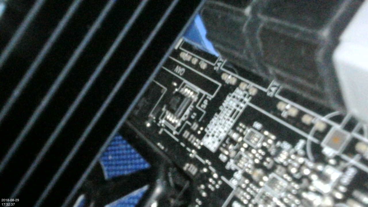
EDIT : I think i found it, cannot verify because located under the graphic card. but it’s badged SPI on PCB…
Show me a good image of the board and I will tell you for sure. 25X40BVSIG sounds correct, is this the one labeled SPI?
Usually they are located near SB or CMOS battery area. I checked some review images, and it looks like I see SPI and BIOS chip right between SB heatsink and top blue SATA Ports
It is the one,
Just under my graphic card, labelled SPI
I will verify when i will disassemble graphic card (watercooled then it s not easy to do) It must be a 25x80 8MB SPI chip It’s the only one that i can’t see with my eyes or smartphone.
This a pict make with an endoscopic camera sorry for poor quality.