[REQUEST] Lenovo X1 Extreme Gen 2 BIOS Dump

I’m hoping to find someone who would be willing to share a working BIOS dump for the Lenovo X1 Extreme Gen 2. Motherboard code is LPM-2 18809-2.

Thank you.

The P1 Gen 2, is similar but I believe not the same as the X1 Extreme Gen 2. I haven’t been able to find a full schematic for the X1 but a schematic of the P1 Gen 2 shows:

‘Table of SPI U2601’ with Winbond W25Q256JVEIQ (WSON) and MXIC MX25L25673G (SOIC8) being listed.

A BIOS dump from fixbios.com with file name ‘Lenovo Thinkpad P1 Gen2,18809-1,W25Q256FV_32MB ,32MB’ tells me that a BIOS dump between the X1 and P1 are going to be different.

Here are some related files.

Edit: —> Links to related content:
[REQUEST] Lenovo X1 Extreme Gen 2 BIOS Dump
Need help recovering laptop after failed BIOS update
Owners of X1 Extreme Gen 2 w/ i9 Processor I Need BIOS Dump
Did I Screw Up? Any Hope for Success? Programming BIOS CHIP
Lenovo P50 Bricked by BIOS update.
Bricked laptop during bios update.

Why a second thread? And why not linking to the help you already got at badcaps?

Well I suppose the two threads here were for two different things; general help request for bios problem, and a [REQUEST] for a bios dump for this specific model of laptop.

I was inspired by this post. Of all the BIOS forums I’ve ventured to, there was a high level of technical experience shown on that thread. I have been getting great help from Badcaps, especially from SMDFlea, but so far I haven’t been able to find a bios dump specifically from a Lenovo X1 Extreme Gen 2 Type 20QV with motherboard LPM-2 18809-2. I’m at the end of the road at Badcaps in terms of getting help and I wanted to see if there is anyone here who might be able further assist.

My situation is very similar, if not identical, to this post. You may have an answer to my overarching question: Can a bootable BIOS be made with what’s available from Lenovo’s BIOS update executable? Is there a way to create a proper BIOS, perhaps with Intel Flash Image Tool, without a full BIOS backup or dump to work with?

Well, there’s a lot of configurations and a lot of different firmwares (thunderbolt for hybrid graphics and intel graphics for example) and a lot of different versions and it’s no longer clear what’s original and working and what’s overwritten.

What’s the machine doing right now when you power it up?

What’s the serial number of the machine?

Which chips did you program / overwrite?

Thank you for the reply,

I do apologize if my posts seemed a bit ‘spammy’. It’s been hit or miss finding help from various forums and I suppose my strategy for posting may have reflected that.

There are definitely many different configurations out there. I believe this may be why it’s been challenging finding a suitable firmware for this machine.

I think what is making this especially challenging is that there are at least 4 different variations of this machine that all share hardware/firmware types:

Thinkpad P1 Gen 2 Type 20QT
Thinkpad P1 Gen 2 Type 20QU
X1 Extreme Gen 2 Type 20 QV (My version)
X1 Extreme Gen 2 Type 20 QW

I’m not sure what’s driving the difference between the sub-models. I thought it could be by processor model but I determined that’s probably not the case after looking through the CPU manifest that comes with Lenovo’s firmware update. Not surprising, but there are three different processors that are shipped with these machines:

i5 906ea
i7 906ec
i9 906ed

However, it looks like there are two versions of firmware updates for all four machines. Per each BIOS update package (i.e. 1.38, 1.39, etc) there are two variants of BIOS firmware updates (i.e. folders named N2OET55P and N2OET55W for BIOS package 1.42 that came out of BIOS Update Utility n2ouj24w.exe).

In other words, as an example, looking at the contents of the BIOS Update Utility for linux for BIOS update package 1.43, the n2oul25w.zip has three cabinet files:

N2OET56P
N20ET56W
N2OHT35W

This website shows that N2OET56 folder ending in W (N2OET56W) may belong to X1 Extreme Gen 2

So, when it comes to these update packages I think there’s enough evidence to say,

Inside each BIOS Update Package

  • N2OET**P type folder or cabinet belongs to P1 Gen 2
  • N2OET**W type folder or cabinet belongs to X1 Extreme Gen 2
  • N2OHT35W belongs to the EC, which may be the same for all 4 machine types

Behavior of machine before programming/overwrite but after failed Thunderbolt 3 firmware update

(1) Firmware update froze, powered off machine by holding down power button.
(2) Turning machine back on by pressing power button; power on button light turns on, keyboard lights up but is unresponsive, cooling fans turn on high constant speed. Holding power button down does not turn off machine, must disconnect battery.

Behavior of machine after programming/overwrite

(1) Absolutely nothing appears to happen. No lights, no fans.

I don’t have a multimeter, (but I should). However, I noticed this the other day.

When I have power supplied via charging cable, and when I have the test clip attached to the BIOS chip, and when the test clip is attached to the programmer, and when the programmer is not plugged into usb, then the red ‘power’ indicator light illuminates on the programmer.

When I do not have power supplied via charging cable, and when I have the battery connected to the motherboard, and the rest of the conditions are the same (programmer clipped on to chip but not supplied power via usb), then the red ‘power’ indicator light turns on only in this instance; when the power button is pressed, the red indicator light turns on for a few seconds then turns off.

In other words,
tl;dr

  • Power is being supplied to the BIOS chip

  • An electrical signal is being sent when I press the power on button.

To sum this all up:
tl;dr

  • The machine doesn’t appear to do anything when it is ‘powered on’ but I have found that at least some parts of the board are still alive. I don’t really see a reason why anything would be damaged at this point so it could be safe to assume that nothing is damaged physically.

  • I have programmed/overwritten just 1 chip off the board, the MXIC 25L25673G 32mb bios chip.

  • I have identified 3 EEPROM chips on the board. Two MXIC and one Winbond. I think BIOS and Thunderbolt 3 are MXIC and GPU is Winbond.

  • Serial number is: S/N R9-0WXXVM 19/12

  • Machine type is: 20QV-CTO1WW

Very long winded, I know. I hope this is all helpful info. It’s not dire that I restore this laptop to working condition … but I’d really like to :smile:.

Edit: I also realize that initially this was most likely a Thunderbolt 3 firmware problem that I assumed was a BIOS problem, which is why I chose to go after the BIOS chip first. Being inexperienced, I made the mistake of not making backups of the BIOS chip before erasing/reprogramming.
Thanks for the serial, there’s a reference to this serial in the file Lenovo X1 Extreme Gen 2 Type QVTestRead1.bin

There are references to the bios versions N2OET40W, N2OET56W and N2OET57W in the same file.

Winbond W25Q80EEW (1.8V) is a NVidia firmware

And yes, the bios package does contain an EC firmware, too.

In MXIC 25V8035F (TBT).bin there’s a reference to N2OTG14W meaning that this is the firmware for hybrid graphics. The content seems structured and the firmware seems to be identical to files of n2otk08w.exe. BUT the redone file from badcaps has some differences, first part of firmware at 0x4000 was redone.

The GbE is still readable in the file you posted, unfortunately there are just 2 different MAC addresses in all the firmware images, one of them identical to the MAC of your dump. That would mean that there’s just one other image around which could serve as example.
Since the ME configuration of your machine no longer can be read there’s a chance the config in the other image is not correct since it seems to come from a P1. Leaves a machine rarely completely dead, but not impossible.

In addition the behaviour the machine is showing now looks very much like EC firmware gone. There should definitely happen something when you press the power button.

Often for this type of bios the EC firmware is copied in the padding in the beginning of the bios region and gets copied afterwards into the EC chip. If there’s nothing or a corrupt EC firmware or something completely different it’ll overwite the EC firmware, normally destroying the ability to update itself via bios region…
But since you don’t have a valid dump there’s much room for guessing here.

Just out of curiousity: Did you check this page? It states it’s at least 18809-2…

Try this file as a desperate try, emptied NVRAM, put EC firmware where it might fit

56Clean1285.zip (8.5 MB)

But again- I think this ‘update from bios’ is dead already and you’d need to reflash the EC firmware directly.

Unfortunately, that 56Clean1285.zip file didn’t work either. I hadn’t seen that post from repairlap.com, so thank you for sharing with me.

I was thinking the same thing about the EC firmware being destroyed/corrupt. I think at this point it’s probably best that I quit here.

Just for the sake of knowledge and repair, I may continue on with this project in the future. If you don’t mind sharing, I’d like to know what needs to be done to program an EC. How/where should I get the files?

I found this post which seems to explain things fairly well.

Thank you so much for taking the time to read over my posts and direct me with some expert thoughts and advice.

p.s.,

I just noticed this broken corner on a small chip. Do you think this might be causing any problems?
broken chip.zip (967.4 KB)

-elzorroazul777

The damaged chip seems to be a coil connected to the network chip according to the plans, so I don’t think it should keep the board from booting.

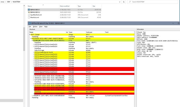
Finding EC firmware- extract the lenovo bios region/ec update with innoextract, check subfolder \N2OET**W. There’s a FL1 file containing a stock bios region- the body of the UEFI volume 6C60EE00-C316-4C95-A684-CDC7E7033311- can be extracted with UEFIToolNE “Extract body”

The FL2 file is the EC firmware with a key at the end, which normally will be cut. Many notebooks put this firmware in the first padding of the bios region- therefrom it’s taken by the EC chip / the PCH / whatever and programmed into the EC chip or it’s SPI.
However- in the Lenovo update there’s a separate flash program for the EC. Even if I couldn’t find information regarding your specific EC chip this program is dated from 2019 (copyright 2012) so your chip might not behave very different to older EC chips.

This program has a built in config that doesn’t seem to fit for your config since it refers to a file N2LHT29W.bin (Your EC is N2OHT**W)

Nuvoton log file

Nuvoton Flash Update Tool - Version 5.0.6.3
Command line: -v -nopause -nshf -vrd -noverify -nocomp -noreboot -lpc -novr -ocv -c flup3.cfg -x 2 N2LHT29W.bin
Opening IOMEM driver…
Disabling IRQ 1 & 12
P_64 save = 0x1c P60 save = 0
CCB42 save = 0x67
Looking for Nuvoton EC Device at address 164E
Address: 0x164F sioId: 0xFF
Looking for Nuvoton EC Device at address 2E
Address: 0x2F sioId: 0xFF
Looking for Nuvoton EC Device at address 4E
Address: 0x4F sioId: 0xFF
Nuvoton EC or Desktop Super IO Device wasn’t found!
Enabling IRQ 1 & 12

Exit Code = 13 (Device not found.)

And the program has some options:

Nuvoton Flash Update Tool optoins

Nuvoton Flash Update Tool Version 5.0.4

Copyright (C) 2010-2012 Nuvoton Technology Corporation. All Rights Reserved.

Usage: flupdate [options]

A file containing the data to program into flash, in binary format

Options:
-h Show program usage.
-v Verbose operation - create a log file and also report
explicit error messages.
-if Select which interface to use:
lpc (default)
i2c
-shf The system uses shared flash (i.e., BIOS and EC FW
are located on the same flash device).
-nshf The system does not use shared flash (i.e., only FW is
on the EC flash).
Note that by default (i.e., -shf or -nshf are not
selected), the flash layout (i.e., whether the system
uses shared flash or not) is detected automatically.
-c Flash Configuration file name. By default, the tool
looks for a configuration file named flupdate.cfg.
-x Select termination option:
0 = Normal Exit
1 = Reset EC
2 = Goto Boot Block (default)
-d Dump the flash data to the file before
downloading/comparing the data.
-sad Stand alone dump. Dump the flash data to the
file without performing download/compare.
-compare Compare the given binary file with the flash data.
In this mode, flash is not programmed. If this flag is
provided in addition to the -ofs flag (see below), only
the bytes starting from are compared.
-bbl Ignore protected sectors.
-lpc Use LPC Memory Access through LPC bus (default is FWH)
Valid only if supported by the motherboard\n");
I/O Controller.
-config Enable shared memory configuration.
-nt Cancel the timeout on flash operations.
-noverify Do not verify flash contents after programming.
-nocomp Program the flash without first comparing its contents
to the binary file data.
(By default, the contents of each section are compared
to the source file, and the section is programmed only
if it is different).
-noreboot Do not ask the user to restart the computer after
download is finished.
-shutdown Power off the computer after the download is finished.
-nopause Start the download/compare without the user approval.
In addition, the application terminates automatically
after downloading the binary file to the flash (without
restart the computer, unless -shutdown is specified).
-cba Set the Configuration Base Address of the device (in
hex format); otherwise, try to locate the device at the
following addresses (in this order): 0x164E, 0x2E,
0x4E.
-sa Set the i2c Slave Address of the dvice (in hex format)
-novr Ignore BIOS model and version check.
-vrd Verify the flash contents after programming using read
command.
-rfp Remove Flash Protection when the protection window
registers are accessible (i.e., not locked).
-ofs Load the provided binary file to the flash starting at
offset from flash start. must be
aligned with the start address of a flash sector. If
this flag is provided in addition to the -compare flag,
only the bytes starting from are compared.
-limit Load the provided binary file to the flash not over
at offset from flash start. must
be aligned with the start address of a flash
sector and not greate than the flash size.
-pfu Enable FW to perform operations before the Flash
Update process starts (Pre Flash Update).
-ocv Override Calibration Values in the flash with the
values provided in the binary file.
-genbsf Generate a Binary Script File (BSF) from a Text Script
File (TSF). The BSF name is the same as the TSF, but
with a different extension (*.bsf).
-runbsf Run the commands in the Binary Script FIle (BSF)
during the Flash Update process.
-s Silent mode. This flag eliminates any user interaction
and minimizes the visual effects
-bec Binary Exit Code. The default exit code upon failure
is a non-zero value. This flag limits the non-zero
value to 1. Thus, the exit code is binary (0 for
success, 1 for failure).
-enkm Do not disable keyboard and mouse during the flash
update.
-acpresent The flash is programmed only if the AC adapter is
plugged in.

Flupdate.cmd:
Optional file.
When Flash Update application is invoked with no command line parameters
it trys to locate the “Flupdate.cmd” file at the current directory.
If the file exists, Flash Update application reads its command line
parameters from this file.

 Example:

    If the Flupdate.cmd content is:

       -c flash.cfg flash.bin

    Then the Flash Update Application run as:

       Flupdate.exe -c flash.cfg flash.bin

So it might be possible to pull a dump of a working machine.

Question with the delivered EC firmware might be if it’s complete or if it’s just the static part and some machine specific parts aren’t included and not automatically rebuilt.

In addition you have already damaged hardware, it’s more and more unclear how damaged this board got in the process.

So if you want to use/ repair this machine:
Buy a used motherboard, dump everything you can before starting it up, try to dump the ec firmware with the Nuvoton software. Then you might try to recover your board with known working firmware- but there may still be damage to the hardware…
There were som hacks using a CH341 on a keyboard port, too, but I don’t know for which chips this worked. I don’t have much knowledge about this type of work, I think you’ll find more regarding EC programming at badcaps.

Would be an interesting project…

1 Like