Hi! I also own a RZ09-0328X Razer Blade 15 Base model (2020), and I just managed to unlock all the options in the BIOS. Your BIOS is bit-by-bit identical to BIOS version 1.06 that you can download from Razer’s website.
Background & bin files
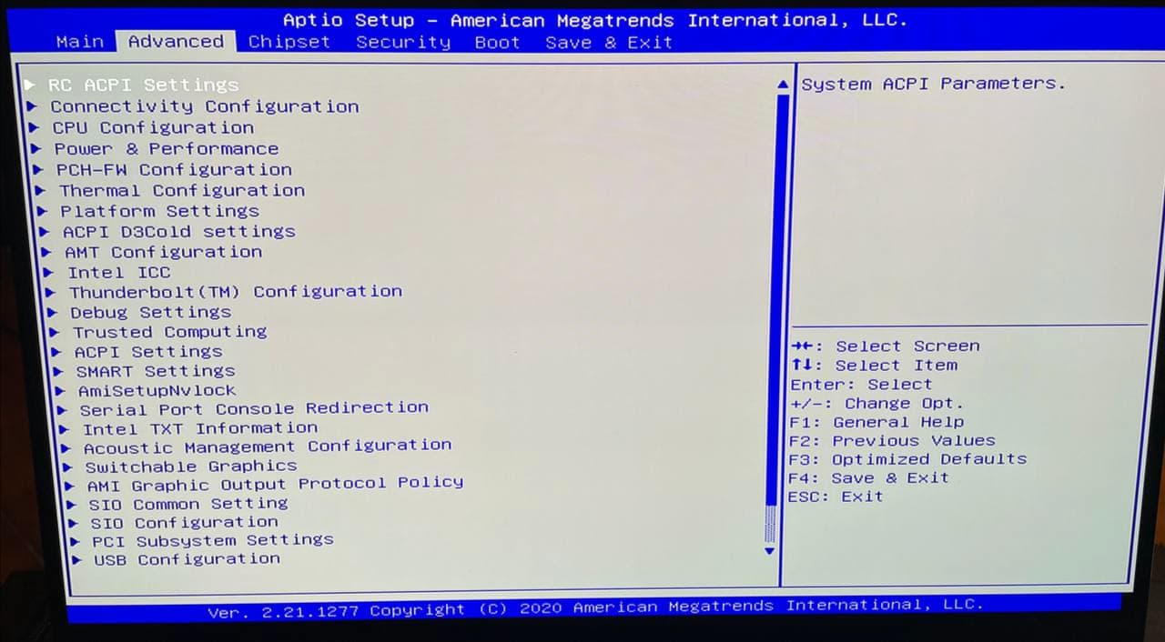
I was trying to unlock the BIOS to enroll my own custom Secure Boot keys, and I noticed that the Razer BIOS has the vast majority of options hidden behind a switch which enables RD MODE (research & development?). That switch is mapped to a byte in the Setup NVRAM variable. Unfortunately the Setup variable is write-protected at runtime. The RD MODE switch itself is suppressed if RD MODE is disabled, so once you disable it, you cannot roll it back. So there are two options:
- Modify the IFR of the BIOS so that the RD MODE option is always visible: Dana5_0106.bin.modified_unhide_rd.
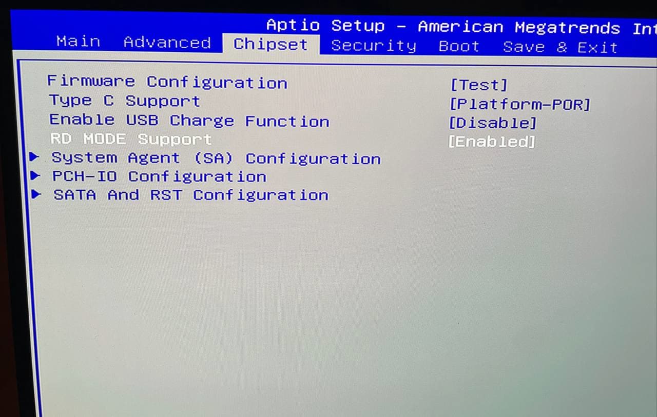
You can then go to Chipset in the BIOS and toggle RD MODE on, thereby accessing all other options.
- Modify the default values of the
Setup variable so that after flashing or resetting, RD MODE is on: Dana5_0106.bin.modified_for_rd_nvram
Option 1 is the usual extraction and modification of the SuppressIf statement which is well documented e.g. here.
Option 2 is my own attempt at getting something closer to the stock BIOS, which would be a little bit more resilient towards e.g. resetting to default settings after fiddling with the CMOS battery.
You can try either of them, at your own risk. I recommend Option 1 to be on the safe side.
Flashing tools
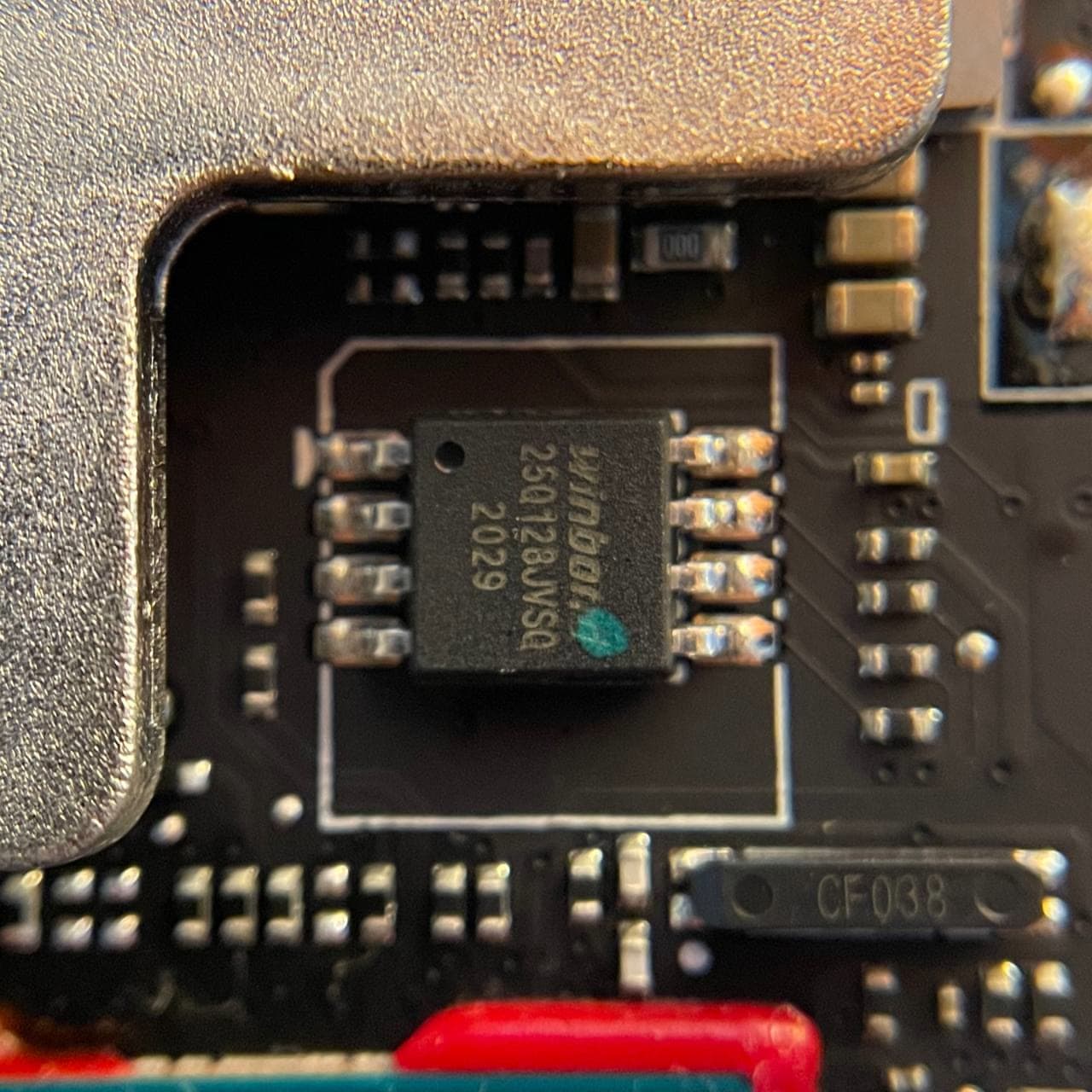
I managed to flash successfully using a CH341A (with the 3.3V modification, since the Winbond chip on my motherboard does not support 5V by spec).
However for doing quick tests, it was much easier to use Intel’s FPT tool. Razer’s BIOS updater ships with a copy of Afuwin (guide here), however that did not work for me (it might still be that it work for you after undoing the write protections, feel free to try). The error that Afuwin gave me was “Secure Flash Rom Verify fail”, like here and here. In any case, if you want to try that, use the version that ships with Razer’s BIOS (unpack the updater with 7Zip to extract AFUWINx64.exe and a copy of the original BIOS).
- Afuwin’s update command (got from Razer’s own updater script):
AFUWINx64.EXE Dana5_0106.bin /p /b /n.
- Intel FPT’s update command (got from running with
--help):
FPTW64.exe -BIOS -F Dana5_0106.bin
My machine has an i7-10750H (Comet Lake), so I used the FPT version I got with CSME System Tools v14.0.20+ r20.
Before flashing though, you need to disable the PCH BIOS lock and SPD Write Disable.
Undoing write protections
While I was fiddling with the BIOS, I looked for all sorts of locks and write protections. I’m listing here all variables that I found that might be related. These are all 1-byte sized variables:
-
FlashProtectionRangeRegisters, VarStoreId: 0x17 (PchSetup), VarOffset: 0x6DD
Disable: 0 (default), Enable: 1
-
SPD Write Disable, VarStoreId: 0x17 (PchSetup), VarOffset: 0x6DB
TRUE: 1 (default), FALSE: 0
-
PCH BIOS lock, VarStoreId: 0x17 (PchSetup), VarOffset: 0x17
Disabled: 0, Enabled: 1 (default)
-
RunTimeVariable Protection Support, VarStoreId: 0x1 (Setup), VarOffset: 0x727
Disable: 0, Enable: 1 (default)
-
CFG Lock, VarStoreId: 0x11 (CpuSetup), VarOffset: 0x3E
Disable: 0, Enable: 1 (default)
-
Overclocking Lock, VarStoreId: 0x11 (CpuSetup), VarOffset: 0xDA
Disable: 0, Enable: 1 (default)
To be able to flash with Intel FPT you need to undo all protections in the PchSetup NVRAM variable, that is, you need to undo SPD Write Disable and PCH BIOS lock. If you have the exact same hardware and BIOS version as me, you can assume the same offsets, otherwise, see the next section.
You do that with RUEFI. There are guides online on how to use it, for example here. In short
- Download RUEFI
- Put it in an ESP partition
- Add a boot entry to boot it (e.g.:
efibootmgr --create --disk /dev/<your disk> --part <partition number> --label RUEFI --loader /EFI/BOOT/ru.efi --unicode)
- Disable secure boot
- Boot into RUEFI. Press enter to dismiss the initial dialog.
- Use
alt+= to list NVRAM variables. Scroll to PchSetup and press enter.
- Navigate to offset
0x17 with arrow keys, type 0 and enter.
- Use
ctrl+pg down to page down until you get the 0x600 offset block, and modify offset 0x6db with 0.
ctrl+w to write PchSetup, then alt+q to quit.- Do not boot into Windows yet. It seems it needs a reboot, usually after quitting RUEFI, I reboot, enter Setup, and then from there boot Windows.
- Now Intel FPT successfully writes.
How to reproduce
This can be useful if you want to do the procedure yourself, or if somebody else with a similar issue (or a different Razer laptop) happen to find this post.
Take a look at this post and this guide to get a sense of what it needs to be done.
- Use UEFITool to open the official BIOS.
- Search for a known string to find the correct section where the IFR is stored. IFR is essentially a compact language to describe the layout of the BIOS application. One such example of a string is “Key Management” or “RD MODE”.
- Once you get a hit, right clik, “Extract Body…”.
- Download IFR Extractor, and invoke it on the extracted file (
ifrextractor body.bin verbose) with the verbose option.
- This generates some
body.bin.0.0.en-US.uefi.ifr.txt file that you can inspect with a text editor.
You can find for example many occurences of
0x34C28: 		SuppressIf  { 0A 82 }
0x34C2A: 			EqIdVal QuestionId: 0x435, Value: 0x0 { 12 06 35 04 00 00 }
Which means, “if question 0x435 == 0x0, then suppress what follows”.
If you search for that QuestionId, you will find where that “question” (a form entry really) is defined:
0x34C30: OneOf Prompt: "RD MODE Support", Help: "Enable/Disable RD MODE Support", QuestionFlags: 0x10, QuestionId: 0x435, VarStoreId: 0x1, VarOffset: 0x764, Flags: 0x10, Size: 8, Min: 0x0, Max: 0x1, Step: 0x0 { 05 91 E9 1B EA 1B 35 04 01 00 64 07 10 10 00 01 00 }
Now, VarStoreId: 0x1, VarOffset: 0x764 tells us the offset in bytes, and the StoreId. The stores are declared at the beginning of the file,
0x27135: VarStore Guid: EC87D643-EBA4-4BB5-A1E5-3F3E36B20DA9, VarStoreId: 0x1, Size: 0x791, Name: "Setup" { 24 1C 43 D6 87 EC A4 EB B5 4B A1 E5 3F 3E 36 B2 0D A9 01 00 91 07 53 65 74 75 70 00 }
So in the Setup NVRAM variable, at offset 0x435, there is one byte that tells whether RD MODE is enabled or not. That is how I found the write/flash protection variables above. At this point you can modify the SuppressIf statement to unsuppress certain questions, for example I tried successfully to
- unsuppress the Key Management option in Secure Boot (that also requires to change Secure Boot Mode from User to Custom by modifying one variable with RUEFI)
- unsuppress the RD MODE switch (gives access to all options)
by changing the sequence 12 06 35 04 00 00 at 0x34C2A to 12 06 35 04 FF 00 with an hex editor (changes “== 0x0” with “== 0xff”, which is not a meaningful value so the condition is always false). Then you can go back to UEFITool, and
- right click on the same section, and do “Replace body…” (if the option is not present, you need a different version of UEFITool)
- Save the new BIOS file.
- Flash it.
This is how I made Option 1 BIOS.
However, I was not too convinced, partly because I didn’t like to have a modded BIOS when the stock one has already all options (I just need to switch RD MODE on), and partly because if I reset to default the options, I need to reflash it. So I thought that the default options must be stored somewhere.
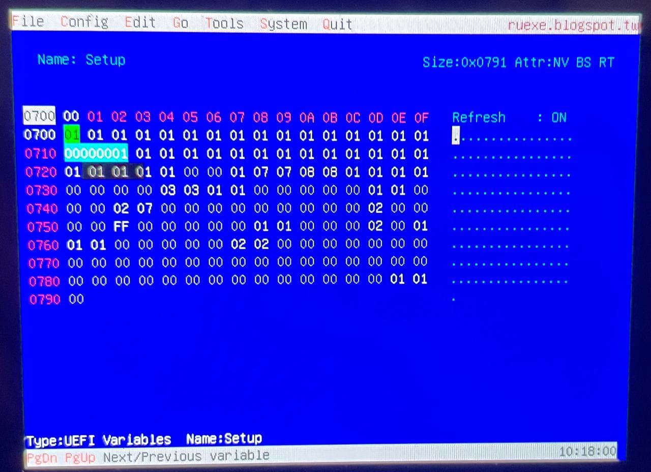
So I opened RUEFI and dumped by hand a sequence of bytes from the Setup NVRAM variable (see picture above), and searched for it in UEFITool. Three regions containing the byte string popped up, and, consistently with Setup being VarStoreId 0x1, the bytes were at the beginning of the regions. Two regions were identical, and the third, which was larger, had the same byte sequence at the beginning as the other two, differing only in some of the last bytes. More importantly, the differences were way beyond the 0x791 byte size of Setup.
I do not know what these regions represent, but if I need to guess, maybe the two identical sections correspond to the “system default” and the “optimized default” settings you can restore in the BIOS, and the larger one is the “factory default” initial NVRAM variables value?
In any case, I found the offset of RD MODE (0x746) into the file by looking at the surrounding patterns, and changed it in all sections to 0x01.
Then I reassembled the UEFI file, and that is how I got Option 2.
Sure enough, after flashing, it rebooted twice and then I was greeted with a lovely RD MODE BIOS.
Hope this works for you! If you encounter issues, I suggest to read first through the forum – two weeks ago I knew nothing about BIOS hacking and I learned everything here. Kudos to the experts who took time to write guides!