Hi,
I am trying to unlock some more options in Bios, but I am really a beginner doing that and I really want to avoid to brick this Laptop.
In the attached zip-file, I included the MEInfo und the bios I extracted with the command >>FPTW64.exe -boot -d biosreg.bin
I also used AFUWINGUIx64.EXE and got the same result. I also dumped the whole bios with >>FPTW64.exe -d biosreg.bin
Secure Boot and TPM was disabled.
I also tried to read the Bios with my Xgpro TL866II Plus but with no success! It seems to be a Windond 25Q80DVSIG. The programmer could not read the IC, even it is supported and I don’t want to desolder right now. Do I have to disconnect the battery to read the eeprom?
Would be great if someone could help to unlock some menus in bios to optimaze power and voltage of that laptop.
Bios is split into two parts.
Additionally, I attached a picture of the bios IC.
bios.part1.rar (4 MB)
bios.part2.rar (2.04 MB)
1 Like
Additional Info:
When I try to flash bach my original Bios, I get:
Error 167: Protected Range Registers are currently set by BIOS, preventing flash access.
Please contact the target system BIOS vendor for an option to disable
Protected Range Registers.
FPT Operation Failed.
So, Bios still seems to be locked!!!
AERO 17 HDR XC bios version is FB03 (2021/01/22)
your product is still supported,i advice against modding your bios.its highly likely that they will release further updates for this device,therefore your modifications will not be permanent
Error 167 means that your ME is locked.
Each motherboard has service jumpers (/ME/FD/FDO) which, when turned on, leave TE on for firmware via FTP.
In your case, you need to know the exact model of the motherboard in order to find shematiс and viewboard on the Internet in order to find the exact location of this jumper.
You need to take a photo of the motherboard from all sides (so that you can see its model)
Finding this jumper will greatly help us to facilitate the modification of the BIOS.
@projektion : I have a similar system and I have unlocked the hidden BIOS menu pages. I will help you, but right now I just do not have the time to go into details.
Regarding your error 167 - in this case it simply means that you BIOS lock var in PchSetup is set to 01 (BIOS Lock = Enabled). You do not need to remove the motherboad, just removing the bottom cover is enough.
Regarding the BIOS chip: the Winbond you are looking at is not the right chip. The BIOS chip in my laptop is above the battery connector, it’s MX25L12873F, a 3.3V chip. Disconnect the main battery (you can leave the CMOS battery connected), and make sure you are grounded prior to reading the chip. Read it several times and verify that you have the exact same file (compare in Hex editor). I used CH431A to read it.
I will get back to you, in the meantime could you do the BIOS dump using the 32-bit version of the FPTw and attach here. You are using version 14.0.20+ r11 ?
The bios attached here was done with FPTw. Must it be 32bit? I did it with 64bit version. I used 14.0.20+ r12.
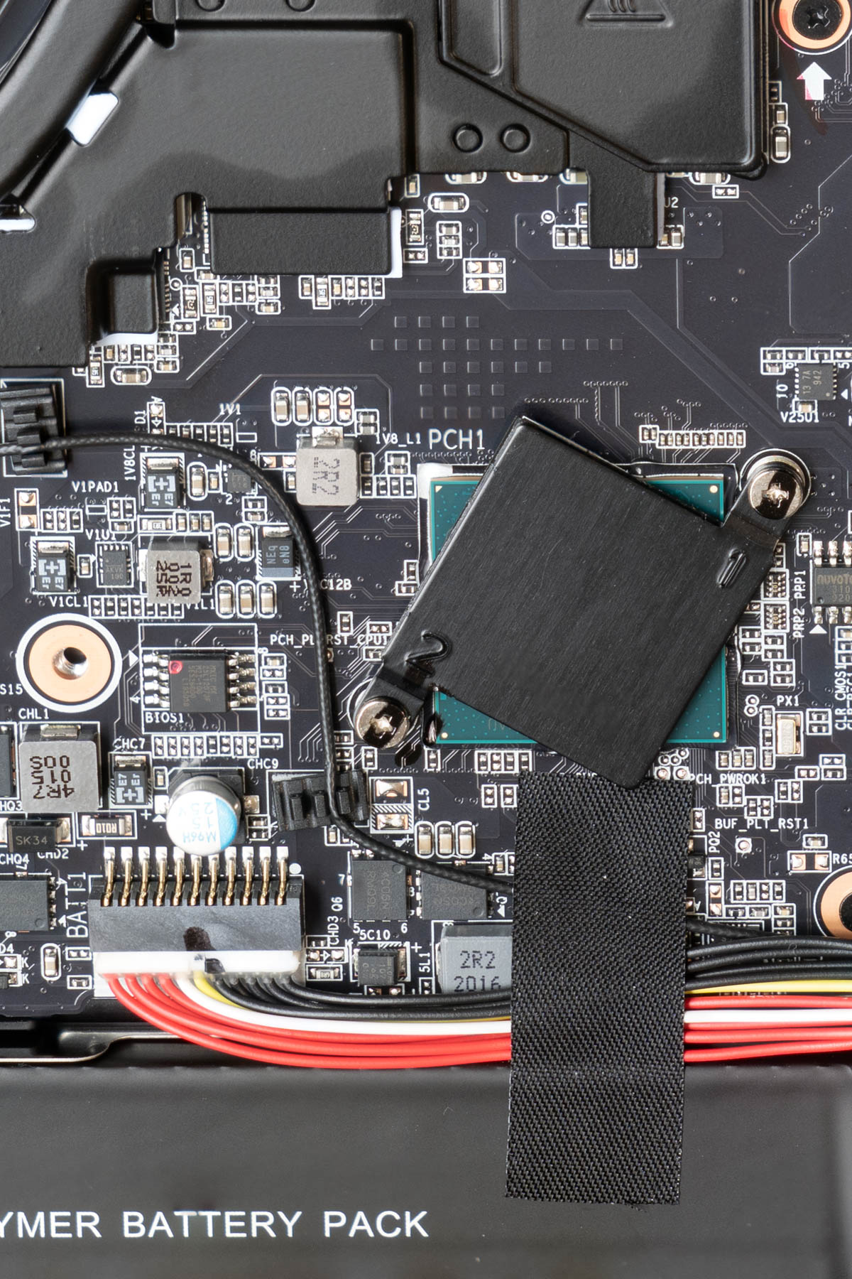
I attached another pictures of the motherboard.
The winbound IC is near the edge of the pcb where the main battery is and next to the bios battery connector (see left top of the picture)!
There is no MX25L12873F on this side of the motherboard.
@nickobar : Which laptop do you have?
The BIOS chip on my motherboard (Aero 17 YB, see photo below) is above the white capacitor above MAIN battery connector, not the CMOS battery coonector. You can see in my photo the bios chip has a red dot in the upper left corner, and under it it reads: BIOS1. I can see from your image that your motherboad is not identical, but it is similar.
From the MEInfo you posted it appears that they used a different BIOS chip in your laptop: yours has jedec code EF4019. The jedec code for my BIOS chip is C22018 (MX25L12873F). I used CH341A to read the chip. Disconnect AC power (obviously) and the main battery, you can leave the CMOS battery connected.
If you like, I can make a mod for you (from the bios dump you posted).
EDIT: @projektion : It looks like the BIOS chip you have (code EF4019) is Winbond W25Q256FV, which is not made in SOIC-8 packaging. According to the datasheet, it’s only offered in 8-pad WSON 8x6-mm, 8-pin PDIP 300-mil, 16-pin SOIC 300-mil, and 24-ball TFBGA 8x6-mm. So it will look a little different, but it should be in the same area of the motherboard.
Hello,
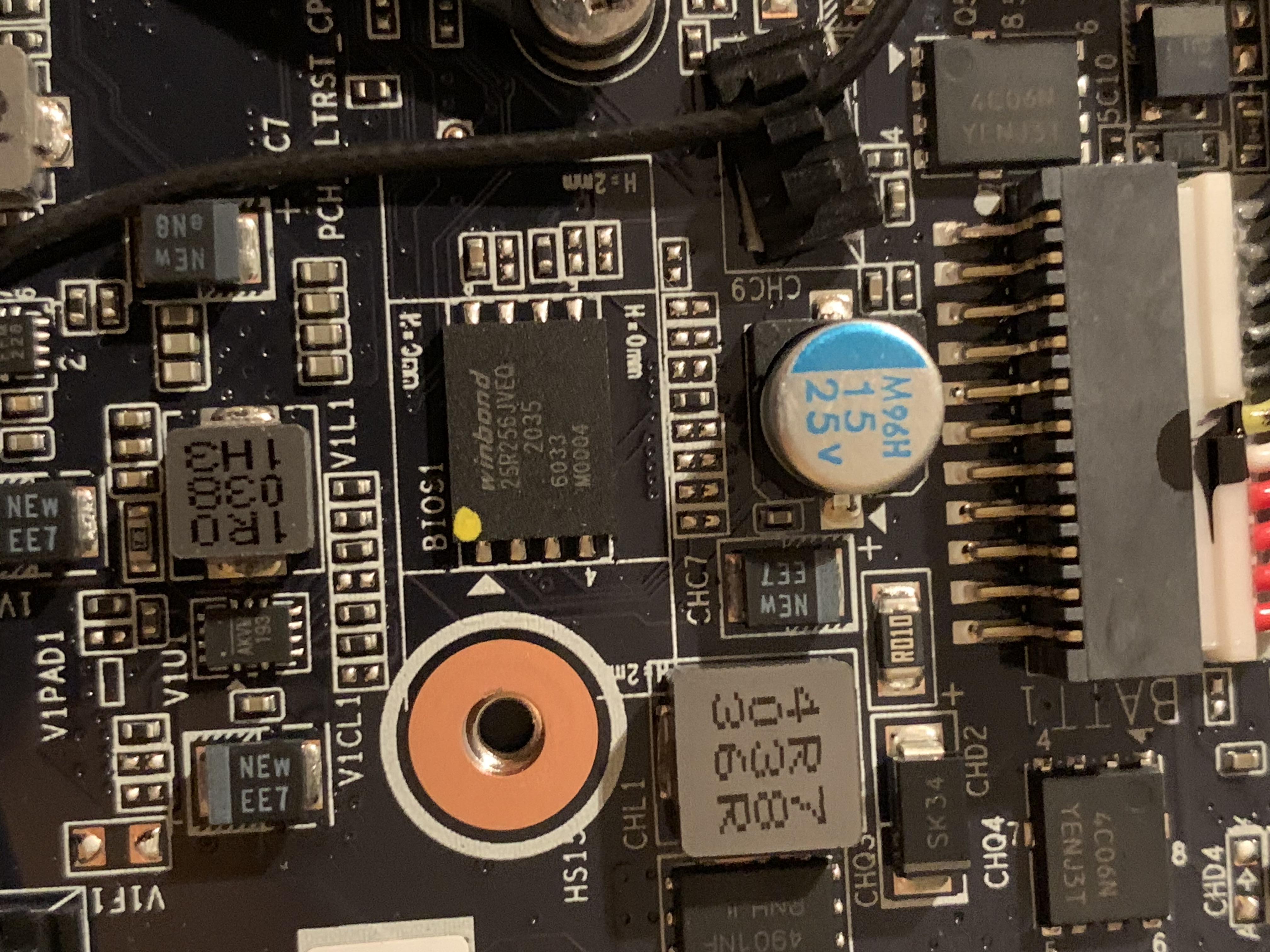
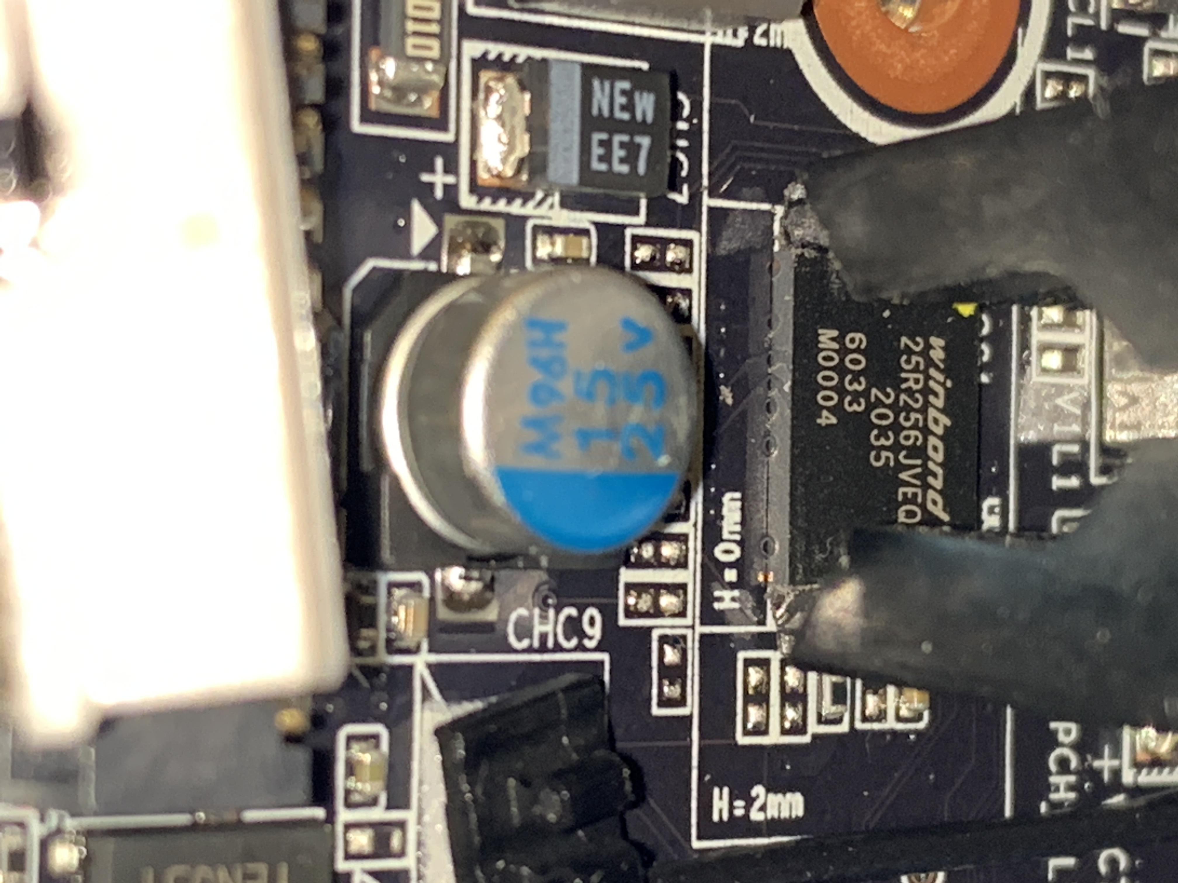
I found the bios IC. It is a Winbound 25R256JVEQ.
So there is no real chance to read / wirte to the IC with the programmer without soldering.
So if something goes wrong, the laptop is broken 
First question is, the bios is locked. I read the posts about unlock, but how do I know it is on the same address as on YB?
So UEFITool and Universal IFR Extractor would not be enought to mod the bios, because I cannot flash it to the chip?!
@projektion : Good to know you found the bios chip
Could you please post a photo of the area with the bios chip - it may still be possible to read/write it.
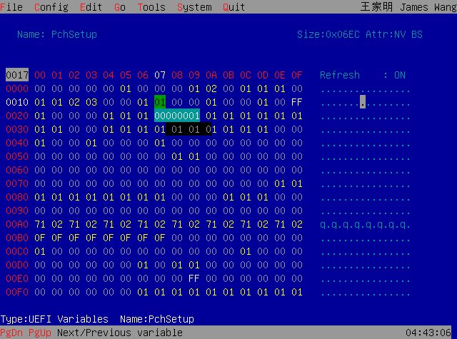
Yes, the bios is locked by default. The BIOS Lock variable in your bios is 0x17 in PCHSetup (same as mine). You can see it from Setup (IFR) extracted from the file you posted:
0x4AAD7 One Of: BIOS Lock, VarStoreInfo (VarOffset/VarName): 0x17, VarStore: 0x17, QuestionId: 0xC6A, Size: 1, Min: 0x0, Max 0x1, Step: 0x0 {05 91 CD 0B CE 0B 6A 0C 17 00 17 00 10 10 00 01 00}
0x4AAE8 Default: DefaultId: 0x0, Value (8 bit): 0x1 {5B 06 00 00 00 01}
0x4AAEE One Of Option: Disabled, Value (8 bit): 0x0 (default MFG) {09 07 04 00 20 00 00}
0x4AAF5 One Of Option: Enabled, Value (8 bit): 0x1 {09 07 03 00 00 00 01}
0x4AAFC End One Of {29 02}
You flash the mod bios (in Windows) using the same Intel Flash Programming tool you used to dump the bios region. You do NOT use the programmer to flash the mod bios.
To dump the bios, open the command prompt and do: FPTw.exe -bios -d biosreg.bin
To flash mod bios use: FPTw.exe -bios -f biosregM.bin
The programmer and access to the bios chip on the motherboard is only needed as a fail-safe, in case something goes wrong.
So you can do this:
1. Make sure you start with completely unmodified stock bios as it came from the factory. With 32-bit version of the Intel Flash Programming Tool create a bios dump typing in the admin command prompt >>
fptw.exe -bios -d biosreg.bin
Keep this bin file safe (in several places and on OTHER media than your laptop), you will need it in case you want to revert back to stock bios.
2. Do the bios mod.
3. Change
BIOS Lock variable 0x17 in PCHSetup to 0 (Disabled) using RU.
4. Flash the mod bios >> fptw.exe -bios -f biosreg.bin
As I said before, I can help you with step 2 if you post your biosreg.bin from step 1. You can make your own mod and see if the files match.
Hello,
@nickobar :
I uploaded the BIOS IC W25R256JV picture.
I even tried to read out the IC with my programmer. It was not possible, no matter what I tried! No way to cantact that pins with the normal adapter.
The Winbound W25Q80, I thought was the BIOS-IC in the first place, could be read without any problem. It seams to hold some data for PCIe Bridge.
The command: FPTw.exe -bios -d biosreg.bin
was already executed and the bios image was already attached in my first mail. there is no difference in the image-file between FPTw.exe and FPTw64.exe.
But for now I will wait for new bios with ResizeBar support before I mod the bios.
@projektion Thanks for the photos of the chip. I am sorry you could not get the SOIC-8 clip connect to it. But looking at your photos: since the legs are exposed the chip can still be read. The way I see it you have at least two options. One: you could modify the SOIC8 clip by first making 8 little "spades" from a thin phosphor-bronze sheet and then soldering each one to the tips of the clip.
Option two: you could try something like this:
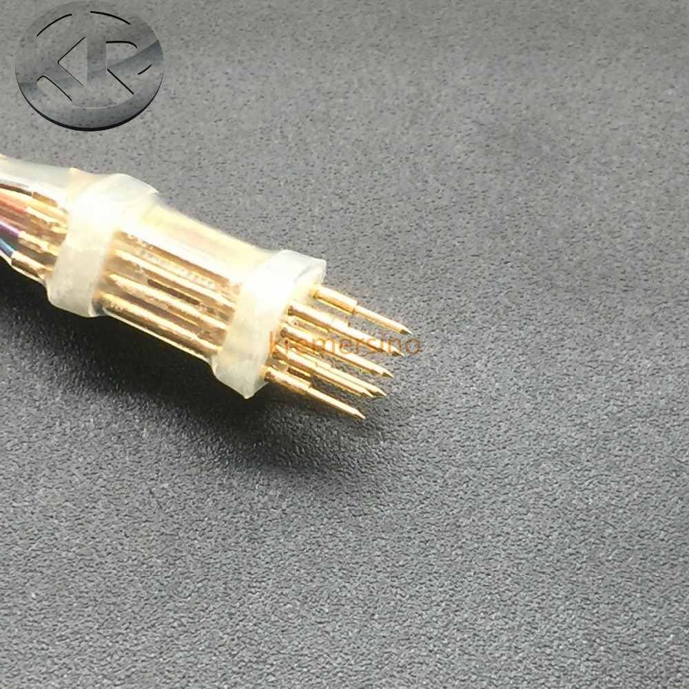
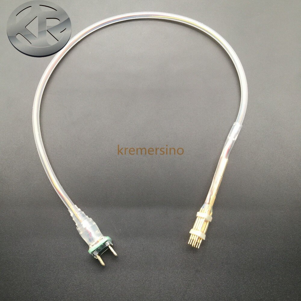
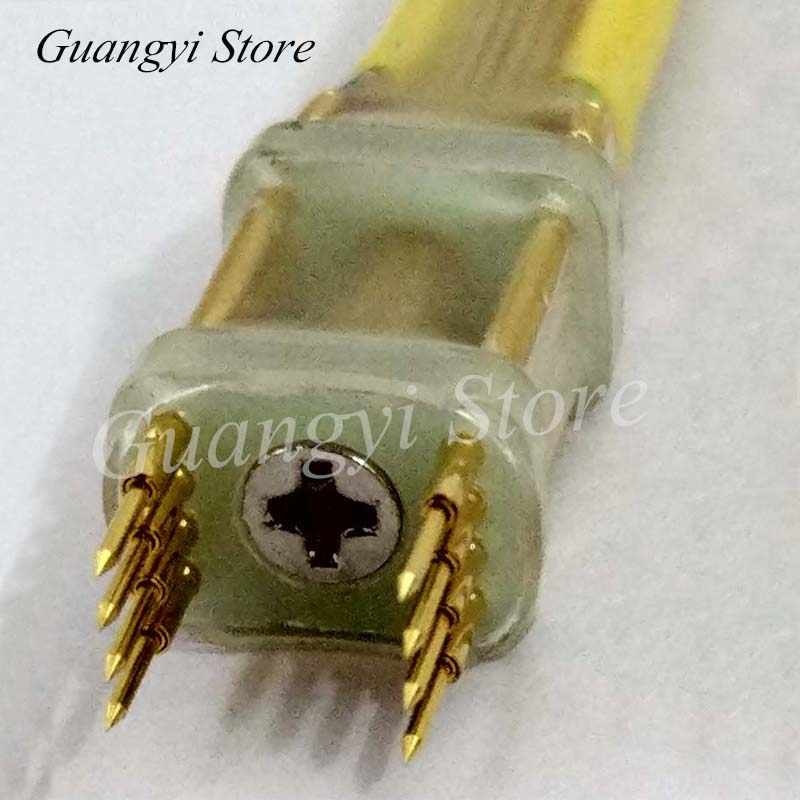
(I found these pics on aliexpress, they look like you will need to hold the connector by hand while the chip is accessed - not ideal, but I think usable.)
Regarding the W25Q80 chip: yes, indeed that holds data for the PCIe bridge - the Intel Thunderbolt 3 controller JHL7440.
I hope they release a new bios with Resizebar support soon, but for now I have attached your mod bios with hidden menu pages unlocked. Here are my notes and edits:
Form ID: 4A 10 59 7B 0D C0 58 41 87 FF F0 4D 63 96 A9 15
Visible:
Form: Main, FormId: 0x2711 {01 86 11 27 09 00} << swap 0x2717
Form: Advanced, FormId: 0x2712 {01 86 12 27 1E 00} << swap 0x2718
Form: Chipset, FormId: 0x2713 {01 86 13 27 1F 00} << swap 0x2719
Form: Security, FormId: 0x2714 {01 86 14 27 3B 00} << left visible
Form: Boot, FormId: 0x2715 {01 86 15 27 20 00} << left visible
Form: Save & Exit, FormId: 0x2716 {01 86 16 27 4E 00} << swap 0x271C
Hidden:
Form: Main, FormId: 0x2717 {01 86 17 27 09 00}
Form: Advanced, FormId: 0x2718 {01 86 18 27 1E 00}
Form: Chipset, FormId: 0x2719 {01 86 19 27 1F 00}
Form: Security, FormId: 0x271A {01 86 1A 27 3B 00} << left hidden
Form: Boot, FormId: 0x271B {01 86 1B 27 20 00} << reveal
Form: Save & Exit, FormId: 0x271C {01 86 1C 27 4E 00}
0x50070 all form list:
4A 10 59 7B 0D C0 58 41 87 FF F0 4D 63 96 A9 15 17 27 00 00 00 00 00 00 00 00 00 00 00 00 00 00
4A 10 59 7B 0D C0 58 41 87 FF F0 4D 63 96 A9 15 18 27 00 00 00 00 00 00 00 00 00 00 00 00 00 00
4A 10 59 7B 0D C0 58 41 87 FF F0 4D 63 96 A9 15 19 27 00 00 00 00 00 00 00 00 00 00 00 00 00 00
4A 10 59 7B 0D C0 58 41 87 FF F0 4D 63 96 A9 15 1A 27 00 00 00 00 00 00 00 00 00 00 00 00 00 00
4A 10 59 7B 0D C0 58 41 87 FF F0 4D 63 96 A9 15 1B 27 00 00 00 00 00 00 00 00 00 00 00 00 00 00
4A 10 59 7B 0D C0 58 41 87 FF F0 4D 63 96 A9 15 1C 27 00 00 00 00 00 00 00 00 00 00 00 00 00 00
4A 10 59 7B 0D C0 58 41 87 FF F0 4D 63 96 A9 15 11 27 00 00 00 00 00 00 00 00 00 00 00 00 00 00
4A 10 59 7B 0D C0 58 41 87 FF F0 4D 63 96 A9 15 12 27 00 00 00 00 00 00 00 00 00 00 00 00 00 00
4A 10 59 7B 0D C0 58 41 87 FF F0 4D 63 96 A9 15 13 27 00 00 00 00 00 00 00 00 00 00 00 00 00 00
4A 10 59 7B 0D C0 58 41 87 FF F0 4D 63 96 A9 15 14 27 00 00 00 00 00 00 00 00 00 00 00 00 00 00
4A 10 59 7B 0D C0 58 41 87 FF F0 4D 63 96 A9 15 15 27 00 00 00 00 00 00 00 00 00 00 00 00 00 00
4A 10 59 7B 0D C0 58 41 87 FF F0 4D 63 96 A9 15 16 27 00 00 00 00 00 00 00 00 00 00 00 00 00 00
0x503A0 short blocked list:
4A 10 59 7B 0D C0 58 41 87 FF F0 4D 63 96 A9 15 17 27 00 00 00 00 00 00 00 00 00 00 00 00 00 00
4A 10 59 7B 0D C0 58 41 87 FF F0 4D 63 96 A9 15 18 27 00 00 00 00 00 00 00 00 00 00 00 00 00 00
4A 10 59 7B 0D C0 58 41 87 FF F0 4D 63 96 A9 15 19 27 00 00 00 00 00 00 00 00 00 00 00 00 00 00
4A 10 59 7B 0D C0 58 41 87 FF F0 4D 63 96 A9 15 1A 27 00 00 00 00 00 00 00 00 00 00 00 00 00 00
4A 10 59 7B 0D C0 58 41 87 FF F0 4D 63 96 A9 15 1B 27 00 00 00 00 00 00 00 00 00 00 00 00 00 00
4A 10 59 7B 0D C0 58 41 87 FF F0 4D 63 96 A9 15 1C 27 00 00 00 00 00 00 00 00 00 00 00 00 00 00
0x50990 long blocked list:
4A 10 59 7B 0D C0 58 41 87 FF F0 4D 63 96 A9 15 17 27 00 00 00 00 00 00 00 00 00 00 00 00 00 00 00 00 00 00 00 00 00 00
4A 10 59 7B 0D C0 58 41 87 FF F0 4D 63 96 A9 15 18 27 00 00 00 00 00 00 00 00 00 00 00 00 00 00 00 00 00 00 00 00 00 00
4A 10 59 7B 0D C0 58 41 87 FF F0 4D 63 96 A9 15 19 27 00 00 00 00 00 00 00 00 00 00 00 00 00 00 00 00 00 00 00 00 00 00
4A 10 59 7B 0D C0 58 41 87 FF F0 4D 63 96 A9 15 1A 27 00 00 00 00 00 00 00 00 00 00 00 00 00 00 00 00 00 00 00 00 00 00
4A 10 59 7B 0D C0 58 41 87 FF F0 4D 63 96 A9 15 1B 27 00 00 00 00 00 00 00 00 00 00 00 00 00 00 00 00 00 00 00 00 00 00
4A 10 59 7B 0D C0 58 41 87 FF F0 4D 63 96 A9 15 1C 27 00 00 00 00 00 00 00 00 00 00 00 00 00 00 00 00 00 00 00 00 00 00
final edits:
0x503A0:
4A 10 59 7B 0D C0 58 41 87 FF F0 4D 63 96 A9 15 11 27 00 00 00 00 00 00 00 00 00 00 00 00 00 00
4A 10 59 7B 0D C0 58 41 87 FF F0 4D 63 96 A9 15 12 27 00 00 00 00 00 00 00 00 00 00 00 00 00 00
4A 10 59 7B 0D C0 58 41 87 FF F0 4D 63 96 A9 15 13 27 00 00 00 00 00 00 00 00 00 00 00 00 00 00
4A 10 59 7B 0D C0 58 41 87 FF F0 4D 63 96 A9 15 1A 27 00 00 00 00 00 00 00 00 00 00 00 00 00 00
4A 10 59 7B 0D C0 58 41 87 FF F0 4D 63 96 A9 15 16 27 00 00 00 00 00 00 00 00 00 00 00 00 00 00
00 00 00 00 00 00 00 00 00 00 00 00 00 00 00 00 00 00 00 00 00 00 00 00 00 00 00 00 00 00 00 00
0x50990:
4A 10 59 7B 0D C0 58 41 87 FF F0 4D 63 96 A9 15 11 27 00 00 00 00 00 00 00 00 00 00 00 00 00 00 00 00 00 00 00 00 00 00
4A 10 59 7B 0D C0 58 41 87 FF F0 4D 63 96 A9 15 12 27 00 00 00 00 00 00 00 00 00 00 00 00 00 00 00 00 00 00 00 00 00 00
4A 10 59 7B 0D C0 58 41 87 FF F0 4D 63 96 A9 15 13 27 00 00 00 00 00 00 00 00 00 00 00 00 00 00 00 00 00 00 00 00 00 00
4A 10 59 7B 0D C0 58 41 87 FF F0 4D 63 96 A9 15 1A 27 00 00 00 00 00 00 00 00 00 00 00 00 00 00 00 00 00 00 00 00 00 00
4A 10 59 7B 0D C0 58 41 87 FF F0 4D 63 96 A9 15 16 27 00 00 00 00 00 00 00 00 00 00 00 00 00 00 00 00 00 00 00 00 00 00
00 00 00 00 00 00 00 00 00 00 00 00 00 00 00 00 00 00 00 00 00 00 00 00 00 00 00 00 00 00 00 00 00 00 00 00 00 00 00 00
The usual !! WARNING !! applies: This BIOS is user specific! If you are not user projektion at
Win-RAID.com forum, DO NOT USE THIS BIOS!!
biosregM-projektion.part1.rar (4 MB)
biosregM-projektion.part2.rar (2.03 MB)
Is it possible to flash stock bios with stock methode after mod?
I found this cables too, but they are quite expensive.
I bought one, will receive it mid of April.
Soldering is really no option to me at this point with a 2500€ laptop only to unhide some bios menus 
I know exactly how you feel - I paid much more than 2500€ for mine just a few months back!
Regarding reading/writing the BIOS chip:
1. You may be able to make your own clip with parts from places like
reichelt.de - they may have the thin sprung pins needed. It might be faster than waiting till mid-April.
2. If you look at your motherboad there is a "Debug Connector" near the BIOS chip. You can investigate if/how this could be used to read/write the chip.
Now to your main question:
I have no personal experience with that because they have not issued any bios update for my laptop. I stongly recommend that you keep the original stock bios dump you made in several safe places (including away from the laptop) so you could re-flash it back if needed.
Gigabyte Aero (15 and 17) and Aorus laptops have similar BIOS, I suggest you read about other users experiences in these threads:
https://www.win-raid.com/t7023f54-Gigabyte-AORUS-G-XB-BIOS-unlock-Request-HELP.html
and
https://www.win-raid.com/t5061f54-Gigabyte-Aero-OLED-BIOS-Unlocking-and-Modding-Issue.html
Also, do not rush to update your stock BIOS before checking that it applied to you. Here is a user on notebookreview forum reported that he flashed a wrong bios onto his Aero 15 XC because apparently Gigabyte published it on the wrong page. His old bios version was FB03, the new version he flashed was HFB07 - I would be immediately suspicious that something is not right just by looking at the version numbers.
@BDMaster and @Nickobar
here is the bios. Please make a mod based on this. now rezize bar is active.
and please tell me how to unlock the bios.
In addition I ask again how to unlock the Bios.
The offsets discribed here #353, does not seem to be correct for my bios:
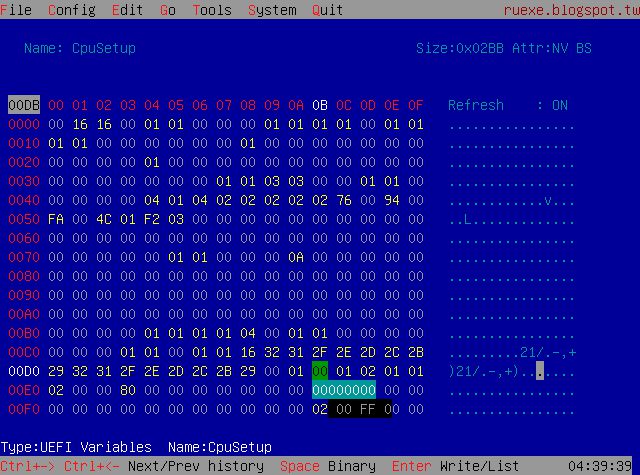
1. Boot into RU Shell
2. Find GUID B08F97FF-E6E8-4193-A997-5E9E9B0ADB32 - CpuSetup
3. Change variable 0xDB from 0x01 to 0x00
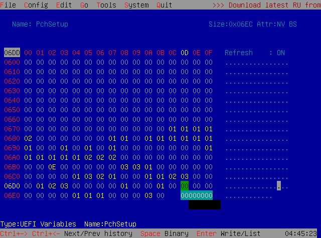
4. Find GUID 4570B7F1-ADE8-4943-8DC3-406472842384 PchSetup
5. Change bariables Flash Protection Range Registers (FPRR) 0x6DD form 0x01 to 0x00 and BIOS Lock 0x17 from 0x01 to 0x00
See attached pics from ru…
bios2.part1.rar (5 MB)
bios2.part2.rar (1.04 MB)
These are the variables from your bios :
0x4AAD3 One Of: BIOS Lock, VarStoreInfo (VarOffset/VarName): 0x17, VarStore: 0x17, QuestionId: 0xC6A, Size: 1, Min: 0x0, Max 0x1, Step: 0x0 {05 91 CD 0B CE 0B 6A 0C 17 00 17 00 10 10 00 01 00}
0x4AAE4 Default: DefaultId: 0x0, Value (8 bit): 0x1 {5B 06 00 00 00 01}
0x4AAEA One Of Option: Disabled, Value (8 bit): 0x0 (default MFG) {09 07 04 00 20 00 00}
0x4AAF1 One Of Option: Enabled, Value (8 bit): 0x1 {09 07 03 00 00 00 01}
0x3E552 One Of: Flash Protection Range Registers (FPRR), VarStoreInfo (VarOffset/VarName): 0x6DD, VarStore: 0x17, QuestionId: 0x75F, Size: 1, Min: 0x0, Max 0x1, Step: 0x0 {05 91 8B 12 8C 12 5F 07 17 00 DD 06 10 10 00 01 00}
0x3E563 One Of Option: Disabled, Value (8 bit): 0x0 (default) {09 07 04 00 30 00 00}
0x3E56A One Of Option: Enabled, Value (8 bit): 0x1 {09 07 03 00 00 00 01}
0x3E571 Default: DefaultId: 0x0, Value (8 bit): 0x0 {5B 06 00 00 00 00}
Flash Protection Range Registers (FPRR) 0x6DD from 0x01 >> 0x00
BIOS Lock 0x17 from 0x01 >> 0x00
Look the GUID 4570B7F1-ADE8-4943-8DC3-406472842384 = PchSetup
Only there … from your shots you’re there 2nd and 3rd and you have 0x17 only to set 0x00 the 0x6DD = 0x00
Try and make a bios backup, then reflash it back to check any errors and then upload it for me …
I will clear it and then modify fo you, let me know …
Please use scewin from a command window as Admin to backup your NVRAM too :
SCEWIN_64 /o /s nvram.txt /h Hii.db /v /q
Upload it for me.
Tool :
https://www.mediafire.com/file/806rvhptz…SCEWin.rar/file
Regards
hello @bdmaster,
I changed var 0x17 in PchSetup to 0x00. After that I read the bios and flashed it back. Here is the output:
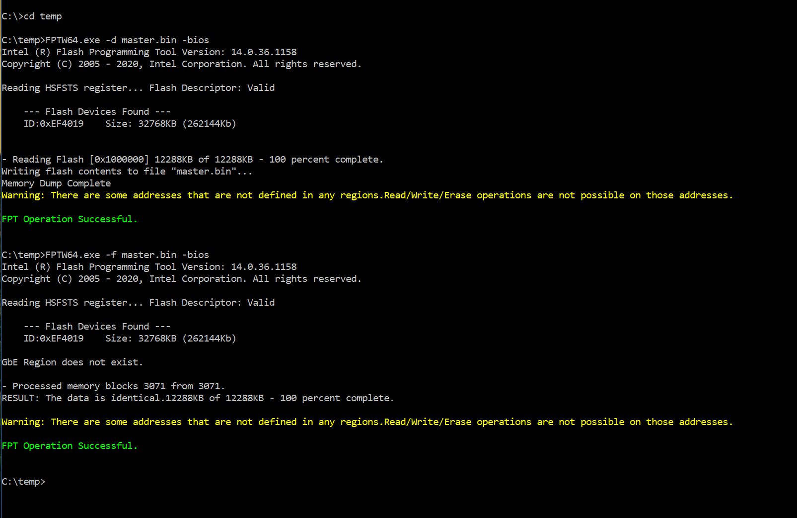
Here is the master bios I read and flashed back:
master.part1.rar (5 MB)
master.part2.rar (79.7 KB)
Here is SCEWin output from SCEWin\5.03.1111\64: SCEWIN_64 /o /s nvram.txt /h Hii.db /v /q
scewin.rar (9.52 KB)
parseFile: non-empty pad-file contents will be destroyed after volume modifications
patch: replaced 2 bytes at offset 503B0h 1727 → 1127
patch: replaced 2 bytes at offset 503D0h 1827 → 1227
patch: replaced 2 bytes at offset 503F0h 1927 → 1327
patch: replaced 2 bytes at offset 50430h 1B27 → 1627
patch: replaced 18 bytes at offset 50440h 4A10597B0DC0584187FFF04D6396A9151C27 → 000000000000000000000000000000000000
patch: replaced 2 bytes at offset 509A0h 1727 → 1127
patch: replaced 2 bytes at offset 509C8h 1827 → 1227
patch: replaced 2 bytes at offset 509F0h 1927 → 1327
patch: replaced 2 bytes at offset 50A40h 1B27 → 1627
patch: replaced 18 bytes at offset 50A58h 4A10597B0DC0584187FFF04D6396A9151C27 → 000000000000000000000000000000000000
Image patched
Your Bios Mod :
https://www.mediafire.com/file/kyxn9vjvu…d_Bios.rar/file
Rename the file as bios.bin and flash it by Fptw64.exe -f -bios bios.bin
Let me know
Regards
Hi@ BDMaster,
ich flashed your BIOS-mod and everything works fine and BIOS is unlocked.
Many Thanks!!!