@Lost_N_BIOS I have been looking for solutions to this issue with Asus H270 and 12/16 threads and someone that did patch an Asus H270 BIOS to make HT work with 12T had other issues such as no USB working before entering the OS - they didn’t say how they modified the BIOS.
As Reactive said, on the Asus ROG Forum someone called spartan_hoplite posted some screeen shots (here and here) of a 9900K running with 16 threads on the G20CI using BIOS 1402 - maybe try to contact spartan_hoplite to ask how they got it to work and for a copy of the modified BIOS?
Although the 9900K would be severly limited by the motherboard VRM and the 180W power brick it could be made to work with some current limiting (IccMax).
@Lost_N_BIOS : didn´t had a look at that module. Will do this soon.
@chinobino : I contacted spartan_hoplite 2 days ago but till now I have no answer.
Currently the main limiting factor is the VRM. As I said, ASUS did not populate one highside MOSFET on their 3phase VRM. So i will mount 3 MosFETs on each highside resulting in less temperatures on that highsideFETs because 2 will be in parallel resulting in half of the Rdson-resistance. Lowside are 2 each phase. Then it should be possible to drive that CPU at 95W after modifing the powerlimits. Currently I only reach 60W (79A VRM), when overclocking VRM to 75W, I get VRM temperature alarm, and at some point it shuts down.
There is place for a 4th phase. this could be for integrated graphics, but this model does not have any hdmi, displayport connector anywhere. So they left it blank, i think. I will do some measurements.
@chinobino - Thanks for the info, hopefully that user will reply to @reactive and send him a mod BIOS and then we can go from there
reactive, can you check his last login date there from his profile? Just wondering if he’s active user, or hasn’t been there posting anything since last year
hello to all
my main is : biostar B250GT3 Ver. 6.x and i use i3 7100
i want move on i3 9100F
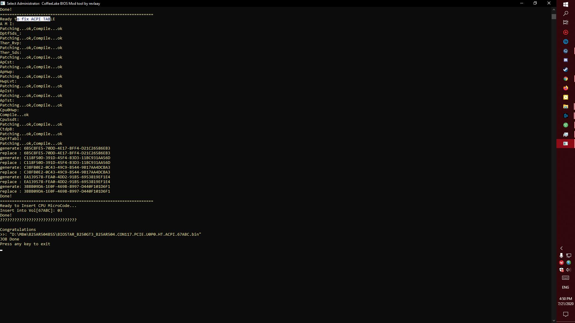
i did mod the last bios in official biostar website and this is my result
1 - is this ok ? or its faild?
2 - and can i use 6 & 7 gen beside 8 &9 gen ? or just 9 gen ?
thanks all and sorry for my English
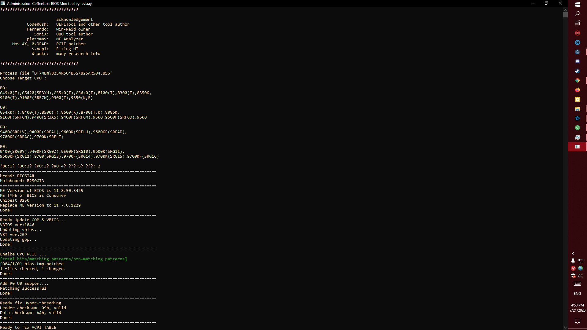
@Lost_N_BIOS - I finally picked up a new chip and tested it and it works properly. This time I used the Ch341 v1.1.1.35 software version and the file you sent me with the name Stock.CTMAPadWkuCGbEFDFIT.bin. This time and after a couple of restarts, the computer started quite normally. I tested both LAN ports and like you said both works perfectly 

 . Later I will test everything with the new processor and report the results.
I’m curious what the trick was to boot the 9900K on a H270 too and if it would work with booting a 9900K on a Z270 BIOS. I’m running a Z370 backported to my Z270 Apex IX which works great, but the Z270 BIOS has a feature that I’d really like to take advantage of; changing multiplier and vcore dependent on temperature. I’ve tried running the Z270 bios through the automated tools, swapping ME versions, enabling HAP bit, and few other things, but I get post code 00.
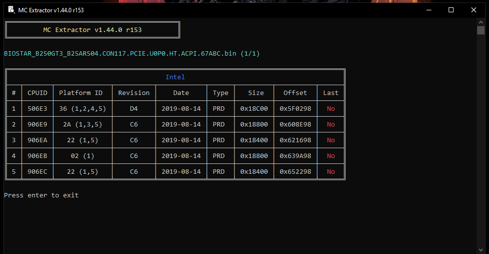
@MrCjxer - Drop BIOS on MC Extractor to see what microcodes are left in BIOS, that will tell you what all CPU’s you can use, we can’t tell from those images.
@Petoparac - Great to hear it bud!  What new chip did you put on there, or same 1.8V Micron one? Great to hear both LAN working too
@ducegt - Trick is properly made Coffee Mod BIOS + Disable HT. For your concern about the settings, are those settings there in the mod BIOS you are using now, and just hidden from you, did you check or do you know how to check etc? If they are there and hidden, I can make visible for you
Enable HAP Bit is not ideal or needed for Coffee Mod BIOS. Please link me to your mod BIOS you are using now, and tell me what settings exactly by name you wanted from the Z370 BIOS, I will see if they are in the BIOS you’re using now and just hidden from you.
hi again
its ok , right ?
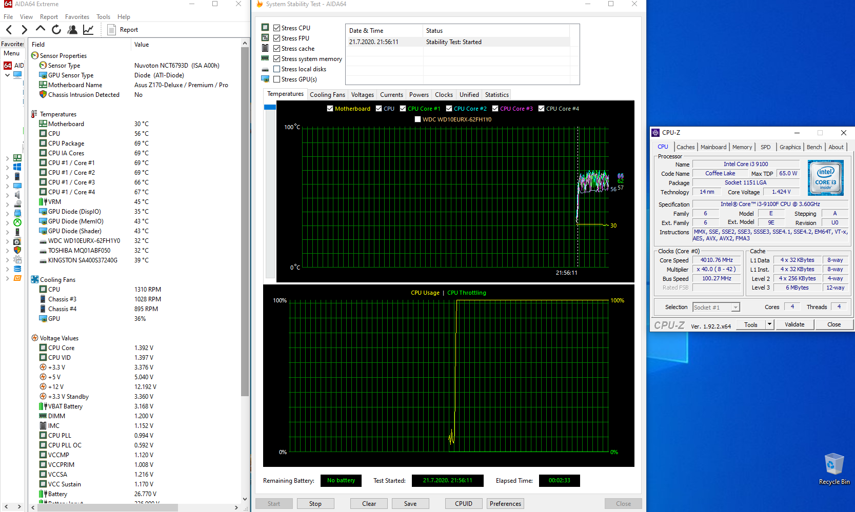
@Lost_N_BIOS - The chip is a Winbond W25Q128 in DIP-package. I put in a new CPU (Intel Core i3 9100f) and everything started without a problem. Windows starts normally and everything works fine and without any problems. Also both LAN ports, wireless and Bluetooth work perfectly. Now I will try to run Cinebench and Aida stress test to see how CPU work.
Do I need to adjust something in the BIOS related to the CPU or motherboard?
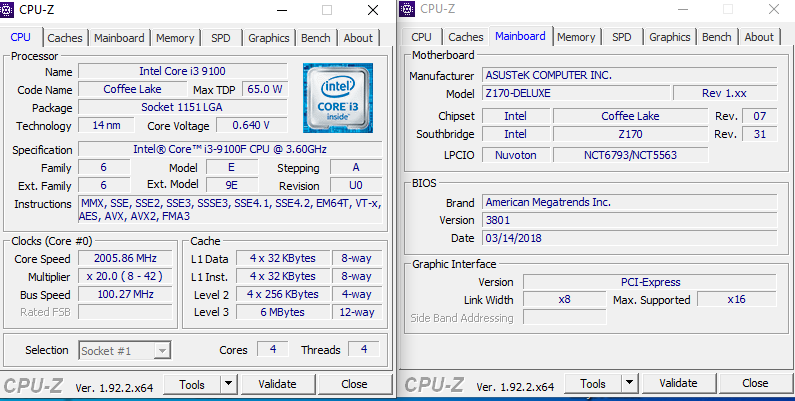
Edit - Is it normal for the core voltage to go up to 1.424v?
@Lost_N_BIOS The H270 mentioned above had all 16 threads working so it must be something else or just a difference in H270 and Z270 chipsets. Thanks for the offer of help, but I’ve already read a lot the great guides you (and others) have wrote so I’ve already checked myself and the feature does not exist\is not hidden in the Z370 BIOS. It’s called CPU Overclocking Temperature Control. The 100/200 series chips and CoffeeLake on OverclockersRU has a table showing Z270 and 8 core CPUs are not supported by modding.
I’ve looked everywhere and have found no explanation as to why 8 cores doesn’t boot on a Z270 BIOS. There’s little reason anyone else would want to do this, but this is such a great feature. It almost looks to me like the logic for this feature… change temperature above X degrees…change vcore above X degrees… etc… exists entirely in the BIOS setup file and perhaps if the offset values, formids, etc were adjusted, the functionality could be added to any Apito V. I understand it might not be possible to add length to the setup though without creating a cascade of other changes that would be too great of a problem to fix.
@MrCjxer - what is your old CPU models you are wondering if still compatible? Only 506E3 and 906E9 is left that is old, if those cover your older CPU models then yes they should still work.
@Petoparac - DIP8? Sorry, I thought you had SOIC chip and Micron one initially, must have been confused with other posts/users
For Asus Z170 you need to do the following, in general
[ASUS] Overestimated VCore voltage (up to 1.5V) in Auto mode is a proprietary bug of ASUS motherboards. The problem is solved by setting the value “0.01” for the parameters “IA AC Load Line” and “IA DC Load Line”. << If you can’t see, let me know and I will further edit CTMAPadWkuCGbEFDFIT for you, and then you can then USB Flashback it in
[ASUS] To remove throttling on 2xxx bios will help the value of “2.1” for the settings “IA AC Load Line” and “IA DC Load Line”
[ASUS] Sometimes for P0 processors the board sets “AVX Ratio Offset” = 1 by default. Microcode 906EC_rev_96 solves this problem.
[ASUS] If the board does not want to start up with an XMP profile or with a known working memory overclocking, then try adjusting the " Boot Voltage VCCIO" and " Boot Voltage System Agent" parameters , setting both “1.1” or “1.2”.
^^ From this thread, section #7
https://translate.google.com/translate?s…78%26start%3D60
See also, 2nd to last post here
https://translate.google.com/translate?s…399%23p16659399
See also, post 5th from the bottom by krestover, for how to do SKTOCC mod to your board instead of doing “Connect” mod to CPU - Or you can connect the two pads on CPU, up to you.
https://translate.google.com/translate?s…333%23p16504333
@ducegt - If you are talking about what reactive linked, for that user linked on Asus forum and H270, yes, he did some kind of backport, which we do not have info on right now.
So the Z270 BIOS has a setting that the Z370 BIOS does not? That is odd, maybe they forgot to add it in Z370, or removed it due to issues? Anyway, if it’s not there/hidden in Z370 base BIOS you are using, then only way to get that setting is to use the Z270 BIOS instead
Table is not always 100% correct, as you can see above reactive is using 9900K in H270 board with H270 mod BIOS (without backport of other series), you just have to disable HT.
And he linked to thread on Asus forum for same H270 system where user posted images without HT disabled too (we assume backport BIOS, but do not know which yet)
If you do not have to disable HT on Z370 backport you’re using on Z270 great, but that has nothing to do with getting the setting you wanted in there, separate issue there and unrelated to making 9900K run on Z270/H270
Yes, you can’t easily just “Add to setup”, setting needs to be there or seen in AMIBCP (so in AMITSE/SetupData), check in hidden debug folder with AMIBCP to be 100% sure it’s not there, checking setup is not the only thing you need to check for this. Link me to BIOS in question if you are not 100% sure.
@Lost_N_BIOS
I have i3 7100 now
Edit :
+Picture
I did flash my bios with moded bios file
And its run with i3 7100
S.M = MOD By revlaay’s ALO TOOL
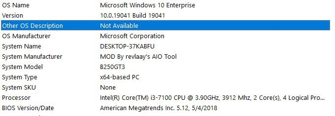
@MrCjxer - Yes, i3-7100 is 906E9 CPUID, so should still be bootable with the BIOS you showed MC Extractor image of, provided that is not a broken mod BIOS.
@Lost_N_BIOS - Setting the value to 0.01 for "IA AC Load Line" and "IA DC Load Line" seems to have solved the problem and now everything is ok. When I run the Aida stress test the CPU is at 4Ghz, the temperature is up to 60 degrees which is 10 degrees less than before and VCore voltage is ok. Everything is the same when I start the Cinebench. Both LAN ports are working and the MAC addresses are set properly. I think that everything is set up properly now and that there will be no problems with the work.
I did not expect anyone to take this much time and knowledge to help me and solve the problem with my BIOS. Thank you very much for everything and if I can help you with anything, feel free to contact me.
@Petoparac - Great to hear, and nice you could see that setting by default too
You’re welcome, glad to hear all is finally working properly and you can now enjoy your system instead of fighting with it 

I am not quite familiar with Z270, but I guess this is not a PCH related, but made by Asus problem. Many Asus 100 series have troubles supporting more than 8 threads with newer UEFIs as well, due to some added Asus routines. Older UEFIs scale wit additional threads just like UEFIs from other manufacturers, but most Z270 probably never got code so old. Instead they can use backports from Z370, which are natively capable to work with more threads, so many modder take the latter route. Apparently lower class Asus 200 do not face the problem at all, so the root cause is probably something ROG specific, but this cannot be fixed by CFL mod tools. Basically one needs to either bugfix a proprietary Asus 100/200 feature to work with more cores or one must implement another proprietary Asus feature into a multicore capable Z370 UEFI. Both means a lot of effort. (And if you are very unlucky, it is not an other feature causing the problems at all, but the very same you desire and Asus could not fix it themselves but simply stripped it from Z370. On that notice: I never noticed temperature related OC settings in my Z170 Ranger. But that might be beause I never really looked for them either, as my private PC still runs a watercooled quadcore.)
@Lost_N_BIOS : I have still no answer on Rog forum from that user.
Meanwhile I did some research on VRM in general and some reverse engineering on my board, finding out that many basic settings like Iccmax or limits are set through resistors connected to the VRM phase controller. Maybe for the first startup sequence while bios is loading.
So is one of that resistors defining Iccmax with 62kohm. When calculating Iccmax with given formula in datasheet you get 79A. Bingo. That’s exactly that what I saw in the settings.
But thanks to Lost_N_BIOS these values are editable in the unlocked menus in BIOS. So I set Iccmax to 111A (value 444). But in order to drive that high current it is necessary to do a hardware hack.
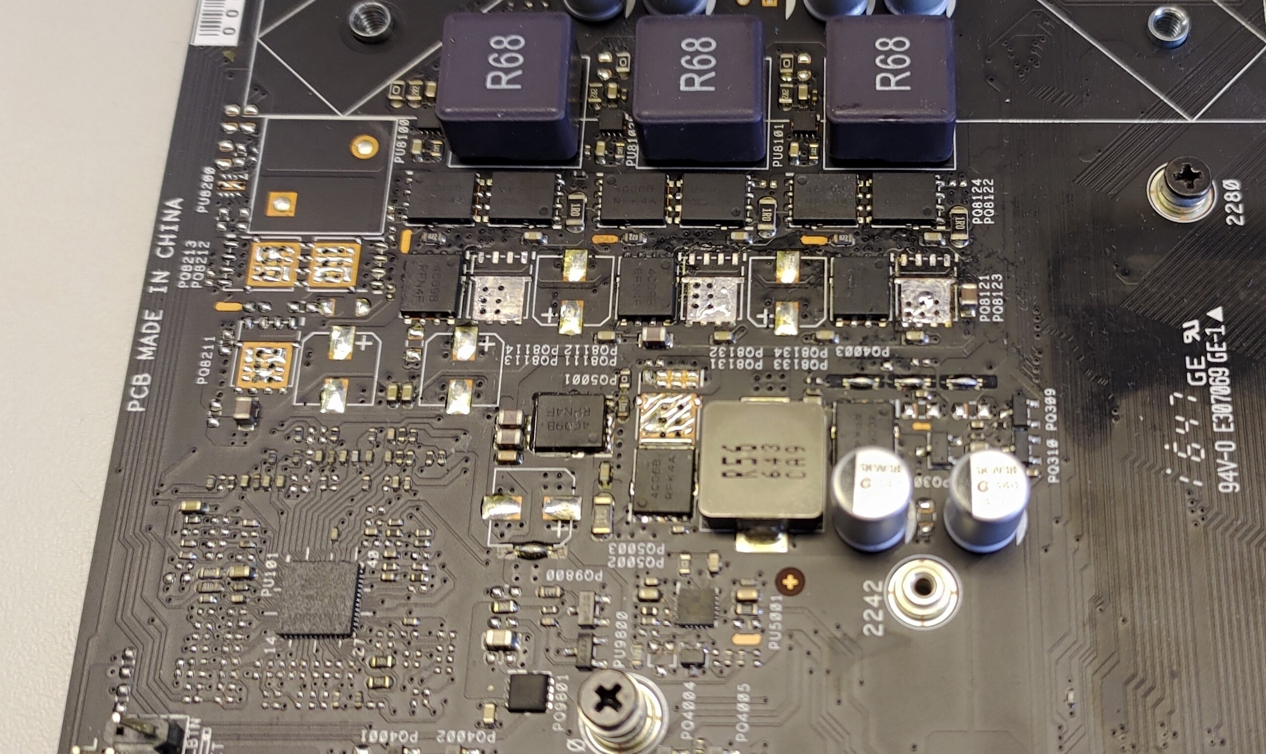
As I mentioned before in this thread I discovered that there are unpopulated FETs. These FETs are located on the high side switching the 19V power supply (yes 19V not 12V). As FETs have a resistance Rds_on higher currents will result in higher temperatures. So using 2 FETs on the high side will result in half of Rds_on and so less temperatures at the same current. Low side does not have to be modified, there are already two.
Before someone wants to modify his board, keep in mind that you really have to know what you are doing. Having professional electronics and soldering skills is a MUST!
Trust me, I know what I am doing.
This Foto shows the default state of a G20CI Mainboard:
Now I modified the board adding identical FETs and some capacitors to buffer the supply voltage:
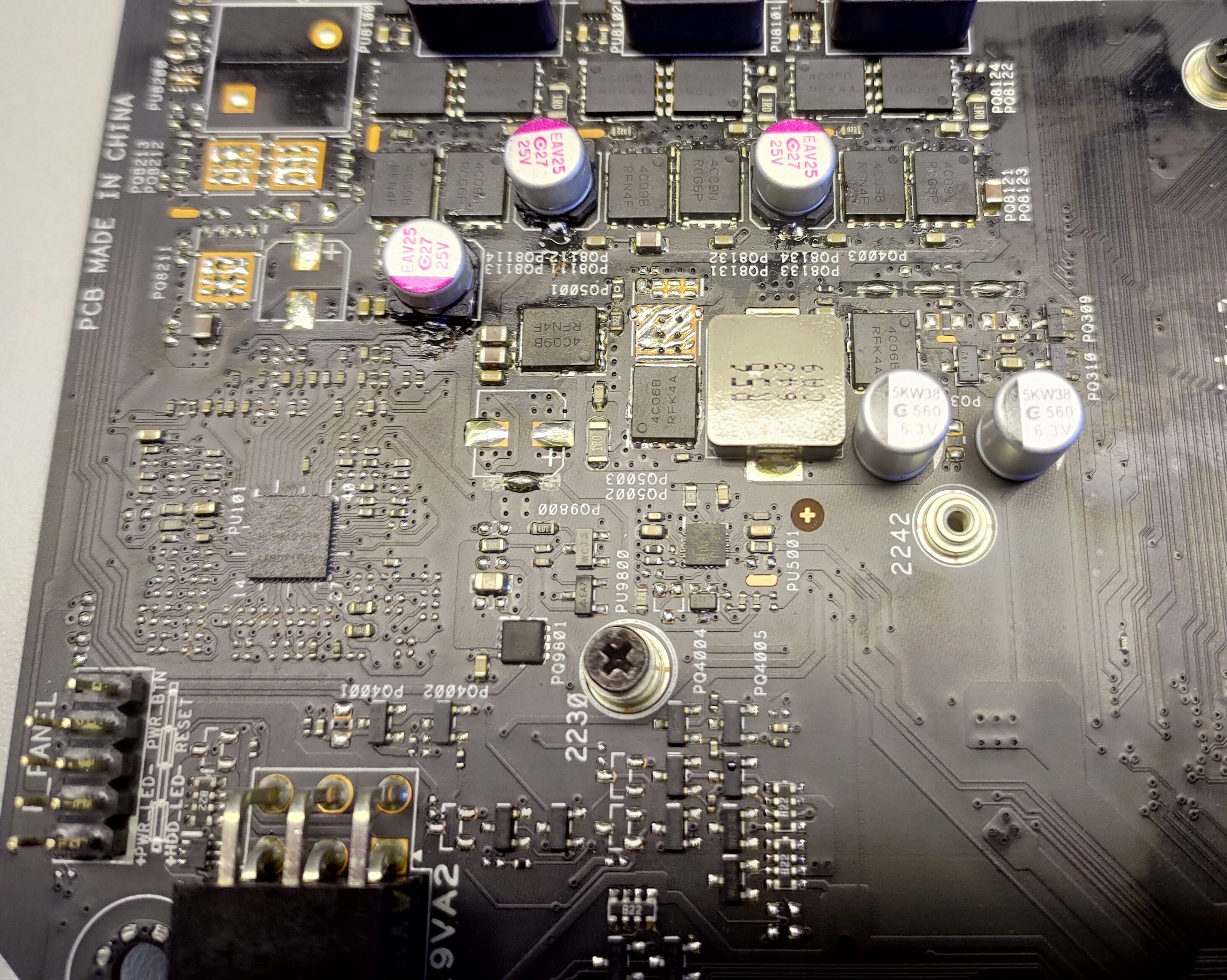
And with added heatsinks:
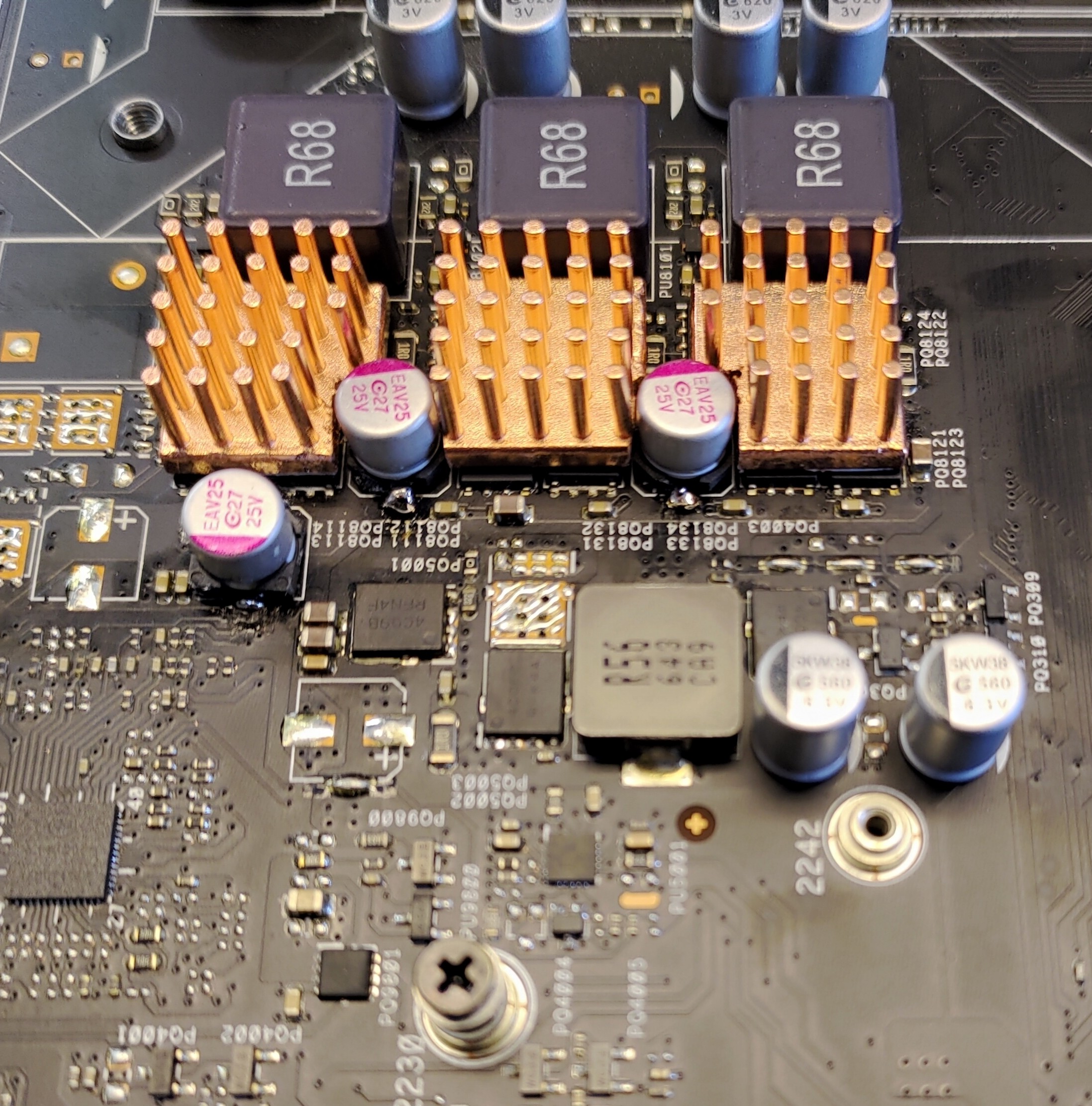
Additionally I added heatsinks to that 3 inductors because they are getting hot too.
Now my 9900k can run at higher currents if requested. Saw it going to a package power of 105W without any temperature issues @4.5GHz and around 60⁰C. (Used liquid metal between heat spreader and heatsink.)
Next thing is HT…
EDIT: In addition i am considering about adding some capacitors on secondary side (the CPU core rail) to change the duty cycle of the PWM perhaps to change the efficiency in a positive way. But it might be necessary to change the inductors too, because these inductors and capacitors are building a "low pass filter". Possibly everything has to be recalculated to match the specifications.
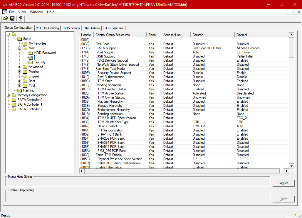
@reactive - look at your BIOS in AMIBCP, be sure to find the hidden debug folder (no name) and check it too. You may find some other settings that will help you, if they are not in hidden debug, if you do I can make them visible for you.
Everything else you mentioned above is above my pay-grade 


HT may be directly tied to that power limit, did you test enable it after your mod above?
@Lost_N_BIOS : I remember that there is a hidden (unnamed) folder in AMIBCP… I will check it today.
Enabling HT is the next that I wanted to test. I had it in my mind, that the power limit could tied to HT. I will post the results.
EDIT: @Lost_N_BIOS : I found an unnamed folder in the Setup->Main Section. But I don´t see what there should be to help me.
I am not quite sure whether the AH/AJ21/22 block missing in A would be requiered for Gigabyte, but B and C are functionally identical. The additional pins covered by B over C have identical specs in both LGA1151 (SKL) and LGA1151 (CFL), so there is definitley no need to isolate them. Pattern B purley exists for convenience: It is damn difficult to match the stagered single pin pattern of C, so most people just cover adjancent pins as well (=> B). Electrically this is an inferior solution as the modded Coffee Lake will run with noticeable LESS active contacts than standard Skylake, while the whole reason for the existance of two LGA1151 revisions is the need for MORE contacts.
(Note: Both B and C recommend isolating F37. While this has been changed from RVSD to VCCin and could cause problems, isoltating it is usually only recommended for Biostar, not for Gigabyte.)
[shameless self advertising]Edit: If you are not familiar with numbering, try this paywall penetrating deeplink: https://www.pcgameshardware.de/screensho…ld03-1-pcgh.png
If your German is better than your English, you might also find the corresponding article helfpul https://www.pcgameshardware.de/Core-i9-9…nutzen-1276543/
[/shameless self advertising]


