How do I get Kabylake microcode preserved instead of Skylake when using the version 2019.1229? Is it more reasonable to use the version 2019.311 (with update
pack 618) for Coffeelake cpus? It seems to keep both Kabylake and Skylake microcodes, in fact, the amount of microcodes increases from 2 to 4.
@Lost_N_BIOS I cannot download Intel CSME System Tools v11 r32.rar. I don’t have antivirus, the download ends but it is not in my downloads
pd :what is the meaning of FPT sorry I’m new
@Lost_N_BIOS Thanks for all the great info.
So if I’m understanding you correctly, the next step should be getting the CH341A + SOIC8 test clip with cable and try to write to the chip? I’ve read kazp3r and yours thread.
Thank you!
@prodan - the way mega works, you have to wait on the original page, then once it downloads, it will then “download” all at once in a second to your downloads folder.
If you can’t get it, I will reupload package for you. FPT is Intel Flash Programming Tool
@lkadlcek - Yes, get programmer and we’ll start there. Can you make your own cables/solder? In case we have to connect to the SPI header, instead of clipping to the BIOS chip?
“@lkadlcek - Yes, get programmer and we’ll start there. Can you make your own cables/solder? In case we have to connect to the SPI header, instead of clipping to the BIOS chip?”
@Lost_N_BIOS Will do! I can solder no problem, just need details about the cable/SPI header if needed later. Thank you!
Will this work fine? https://www.amazon.ca/KeeYees-SOIC8-EEPR…TS7E791ZB96BD60
@lkadlcek - Yes, that kit will be fine - SPI header info here
https://www.elmorlabs.com/index.php/foru…header-pinouts/
Image I posted here
Allow B0 stepping on Asus W621E Sage (7)
See also, these pages for many more links/images/info on Asus pinout
Bricked my ASUS prime h270 while trying to downgrade UEFI
Using a Netgear PCI Ethernet card to flash bios.
More info here, someone making a cable on second page
https://rog.asus.com/forum/showthread.ph…p-PCIe-x16-slot
I’m not sure if dupont female will fit into the headers, but they are cheap cables you can get in large sets of 10-30 etc.
Maybe if you get M/F you can remove the plastic part on the female end, then they would slide onto the SPI header. If not, you will need to find correct pitched female connect ends.
The Male end of dupont cable fits into CH341A without issue.
@Lost_N_BIOS I have ordered the programmer, should arrive in a day or two.
Thanks for the additional info on the SPI header, but if I understand correctly the CH341A + SOIC8 test clip with cable might work and we would be going the SPI header way only if this fails, right?
@Lost_N_BIOS
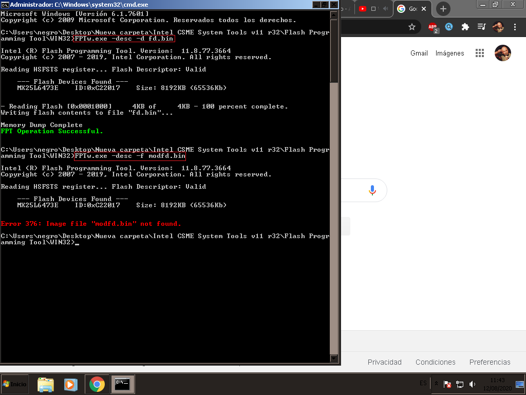
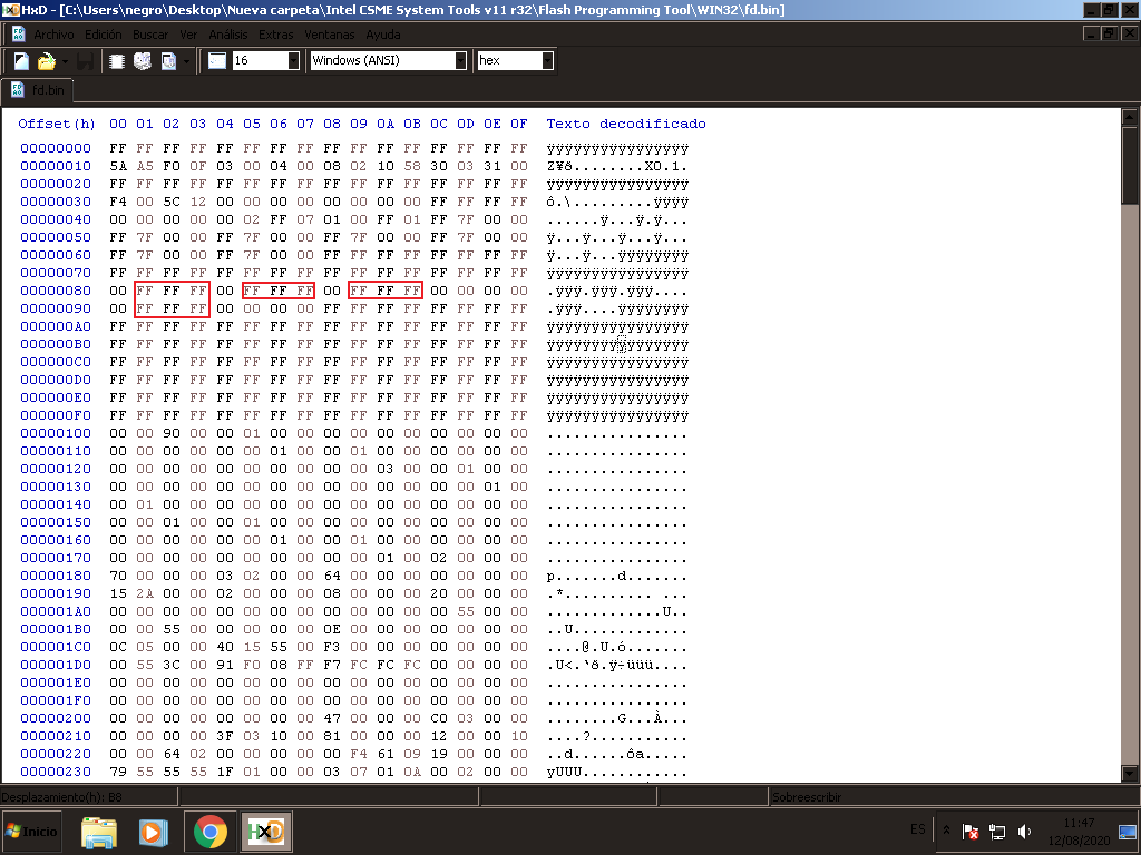
***FPTw.exe -desc -f modfd.bin *** I can’t understand the last step. I run "FPTw.exe -desc -d fd.bin" I enter FD but I don’t have to modify anything it is like in the image, I run "FPTw.exe -desc -f modfd.bin" but it gives an error 367 (image below). the command should be FPTw.exe -desc -f fd.bin? (or MODfd.bin). Thank you
PD: my i3 arrived is (SRF6N) . NO (SRF7W) the steps are the same? I know that the CPU Socket pinwork is required. "U0"
I used the version 2019.1229 and it did work. Had to lower ME version manually though. Now I have both Kaby- and Skylake support and the number of "modules" 2 → 4 as mentioned. The microcodes here are not very fresh so I need to work on this.
As an interesting side note, the built-in flasher rejected a CoffeeTime0.85a patched mod (secure flash check fail) and I know the tool itself recommends to not use this option. Maybe I should consider ordering a programmer before I run out of luck.
Hi @Lost_N_BIOS , I’ve got the CH341A programmer with the clip, when you get a chance please let me know the next step should be.
Thank you.
@prodan - You are correct, your FD is already unlocked then. The error in your image is due to file not found at location you are running that command.
But, if your FD is already unlocked, there is nothing for you to mod, thus you should not have created any modfd.bin file anyway  modfd.bin >> This could be any name, I just used that as example of edited fd.bin file name
Please, lets confirm what you can and can’t write, so we know proper steps you need to take to flash full mod BIOS (may be needed to flash certain parts with FPT and certain you can use stock flash method for example >> BIOS region)
Please dump the following and send me the files, so I can make you mod BIOS. Then also, test writing them back with FPT, tell me what error number you get, if any, on which command
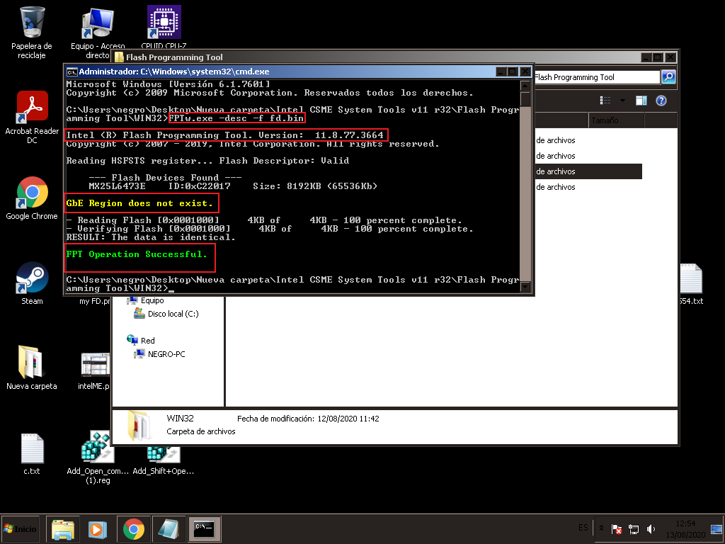
1. FPTw.exe -desc -d fd.bin >> To write it back >> FPTw.exe -desc -f fd.bin
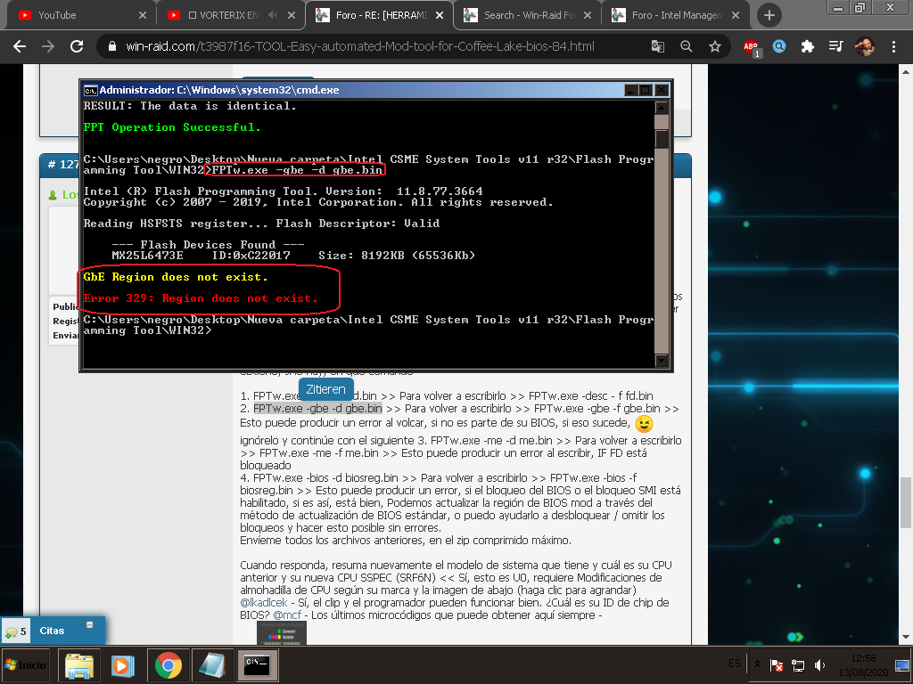
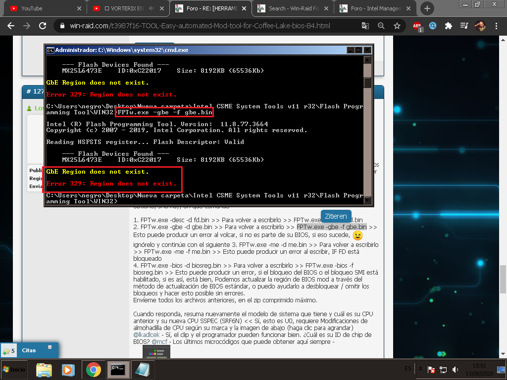
2. FPTw.exe -gbe -d gbe.bin >> To write it back >> FPTw.exe -gbe -f gbe.bin >> This may error to dump, if not part of your BIOS, if that happens, ignore, and move on to next
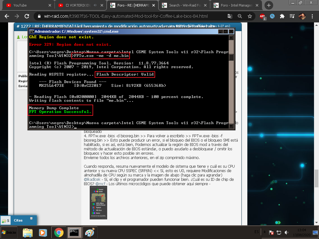
3. FPTw.exe -me -d me.bin >> To write it back >> FPTw.exe -me -f me.bin >> This may error on write, IF FD is locked
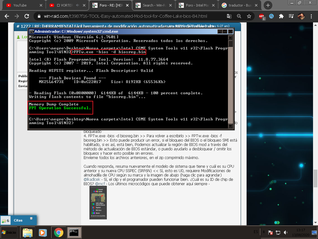
4. FPTw.exe -bios -d biosreg.bin >> To write it back >> FPTw.exe -bios -f biosreg.bin >> This may error, if BIOS lock or SMI lock enabled, if so, it’s OK, we can flash mod BIOS region via standard BIOS update method, or I can help you to unlock/bypass the locks and make this possible without error.
Send me all of the above files, in max compressed zip
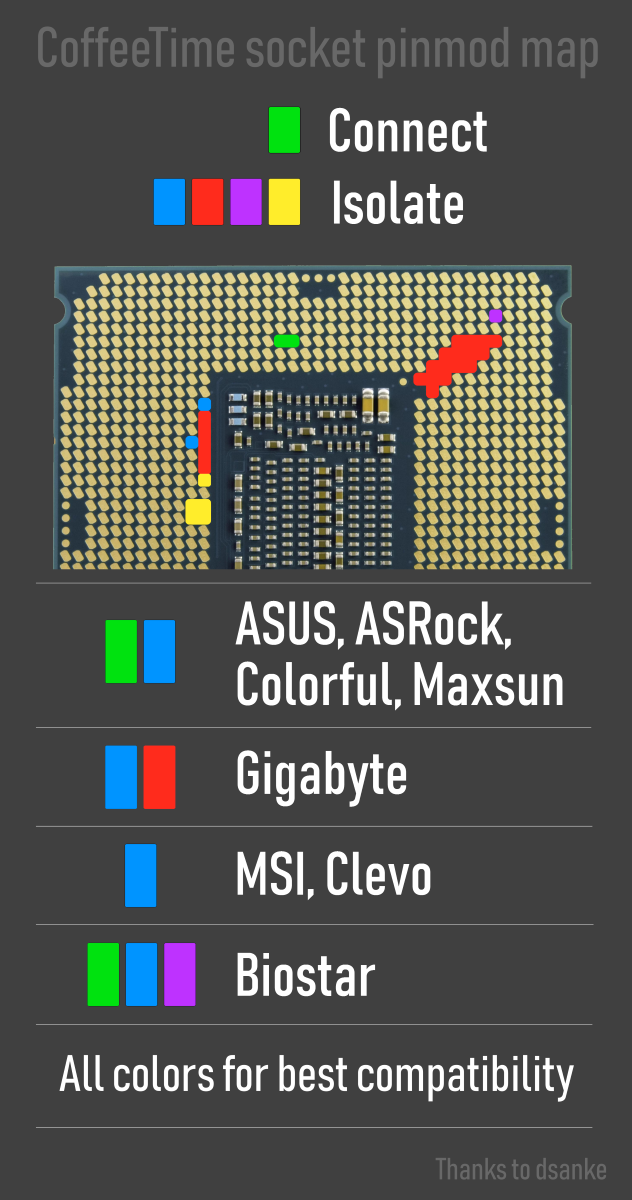
When you reply back, please summarize again, what model system you have, and what is your old CPU and new CPU SSPEC (SRF6N) << Yes, this is U0, requires full CPU pad mods per your brand and the image below (click to enlarge)
@lkadlcek - Yes, clip and programmer may work fine  What is your BIOS chip ID?
@mcf - Latest microcodes you can get here always - https://github.com/platomav/CPUMicrocodes/tree/master/Intel
For Asrock mod BIOS, you must remove the Instant flash protection first, before you can flash it. You can do this by running the BIOS (Dump, stock, already modified etc) through UBU program, and do nothing except at end when asked to remove protection say yes and then choose mod BIOS file name.
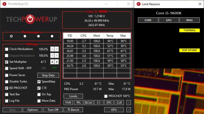
Hey guys I still have these limits, can I do sth about it?
@Lost_N_BIOS
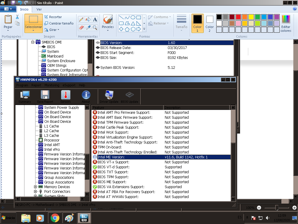
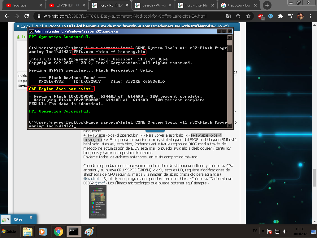
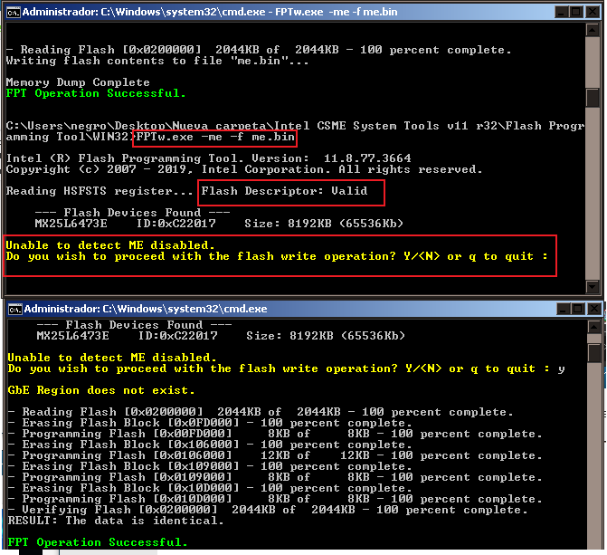
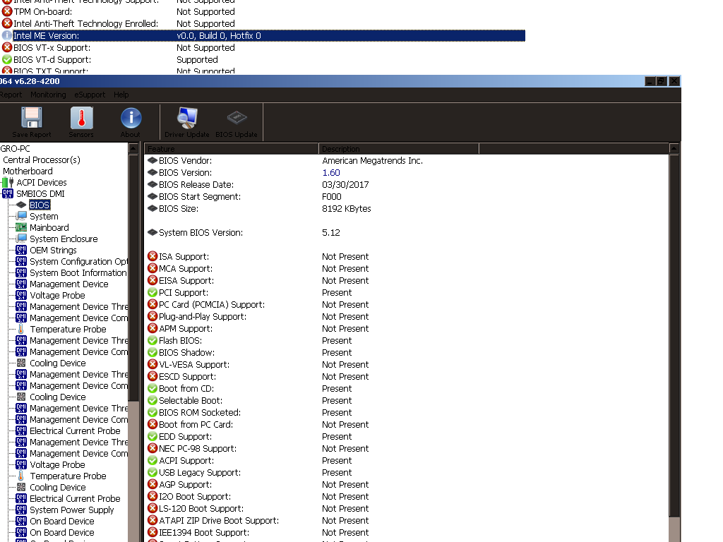
After running all the commands I only got error in FPTw.exe -gbe -d gbe.bin (Error 329: gbe.bin GBE region does not exist) and FPTw.exe -gbe -f gbe.bin same error. after executing all the commands, I restart my pc and freeze windows which turns off the button. I turn on my pc and I get a black image and the EZDEBUG led on from msi , wait 1 minute (nothing worked, keyboard mouse etc). I turn off again but this time I leave my source without power for 2 minutes (with tears in my eyes) I turn on again and I see some letters say something about ME FW similar or equal to when I did pinmod “E.1” and I start windows I check hwinfo and my ME it is now 0.0.0.0. This is good ? is the black image normal? my sspec
MSI h110m pro vh - plus > https://www.msi.com/Motherboard/support/H110M-PRO-VH-PLUS
Windows 7 (64bit) ultimate service pack 1 (6.1.7601) compilation 7601
ram 8gb (1stock) 2133hz Crucial
Current CPU G4400 (SR2DC) Upgrade i3 9100f (SRF6N)
PD:These dumps were made with the g4400 igpu, should I have done it with my gpu? gtx 670
I leave images in case I help someone else.
if you have time look at the photo to check if it is correct (I’m scared) thanks anyway
http://www.filedropper.com/fd-biosreg-me
1 Like
Hi everyone
Is Asus h110 m-k prime good for mod ?
For I3 9100F
Thanks
I tried the 1009 and up but it just won’t boot up.
I will tried the 0906 later this weekend since at least your RGB is working. ![]()
Update: 0906 won’t boot up my 9900k, will revert back to 370f port RGBless
@svarmod any insight?
Hi Bro ,
i’ve used this z270f below and RGB works
This guy called dsanke on the Chinese site smxdiy.com successfully modified the following bios to accept coffee lake achitechture CPUs on z270i motherboards. Intel told us it couldn’t be done. yeah right.
if anyone wants to try it out there, here are the modified files, based on the modified version of the BIOS:
MAXIMUS-IX-APEX-ASUS-0906
MAXIMUS-IX-HERO-ASUS-0906
STRIX-Z270E-GAMING-ASUS-0906
STRIX-Z270F-GAMING-ASUS-0906
STRIX-Z270G-GAMING-ASUS-0906
STRIX-Z270I-GAMING-ASUS-0704
ROG-MAXIMUS-X-APEX-ASUS-2203
ROG-MAXIMUS-X-HERO-ASUS-2203
ROG-STRIX-Z370-E-GAMING-ASUS-2401
ROG-STRIX-Z370-F-GAMING-ASUS-2401
ROG-STRIX-Z370-G-GAMING-ASUS-2401
ROG-STRIX-Z370-I-GAMING-ASUS-2401 http://www.mediafire.com/file/9elrxfv3f2…270-TO-Z370.zip
more info on the thread in Chinese. http://www.smxdiy.com/thread-2389-1-1.html
1 Like
@Lost_N_BIOS Hi, sorry for the delay, you can see the pic of my Bios chip on the bottom of the page 84, or do I need to look elsewhere to get the bios chip ID? Sorry for all the noob questions ![]()
@lkadlcek - Ohh yes, sorry, I commented about that chip ID at post #1261, top of page 85
@prodan - Yes, if GbE does not exist to dump, then same error will happen to write (well different error, since you did not create any gbe.bin file, it will be file not found error  )
)
Sounds like ME FW was messed up during this test, it’s OK, we will fix it, don’t worry But, I see in your image, ME Disabled before you dumped or wrote ME, so it would have been N/A or 0.0.0.0 before this/already.
GPU used does not matter
Here is coffee mod BIOS, based on latest BIOS 1C - Flash it back using the following procedure, while using G4400 CPU
1. FPTw.exe -desc -f ModE7A15IMS.1C0
2. FPTw.exe -me -f ModE7A15IMS.1C0
3. FPTw.exe -greset << Here, before you run this command, be ready for auto restart. If system does not auto restart, please shut down, turn off PSU at switch, press and hold case power on button for 10-15 seconds, then clear CMOS, then wait 1+ full minute before you restart system
4. Rename ModE7A15IMS.1C0 to >> E7A15IMS.1C0, then reflash this via M-Flash using built in BIOS flash tool and USB.
Then you can shut down and put in coffee CPU  Be sure you did pad mod on CPU per “MSI” from image at post 1272
FYI, this mod has 506E8 microcode removed - This is stock modified BIOS, anyone can use this, BUT I’ve added user MAC ID in text/pad area, if you use this and you are not user “prodan” put your MAC id in there instead via HEX editor at 0x640056h-0x64005Bh
http://s000.tinyupload.com/index.php?fil…923019528246093
@MrCjxer - Yes, you need flash programmer or to do pinmod though, to unlock FD so you can write mod FD/ME region.
What is SSPEC of your 9100F? If B0 (SRF7W), then you do not need to write in mod FD, only make sure ME FW is not 11.8 version, then you are OK (also, no CPU pad mods needed either.
1 Like
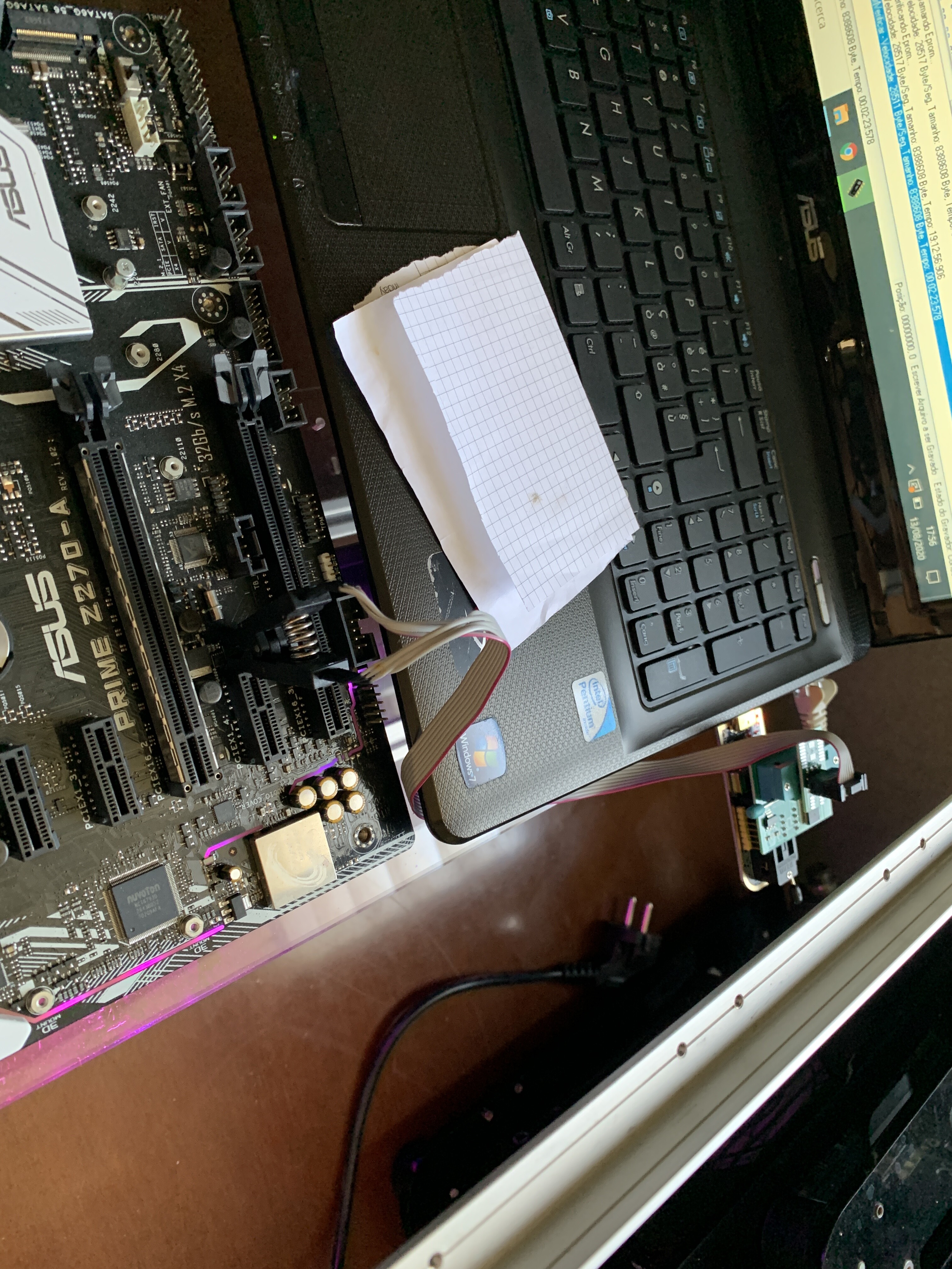
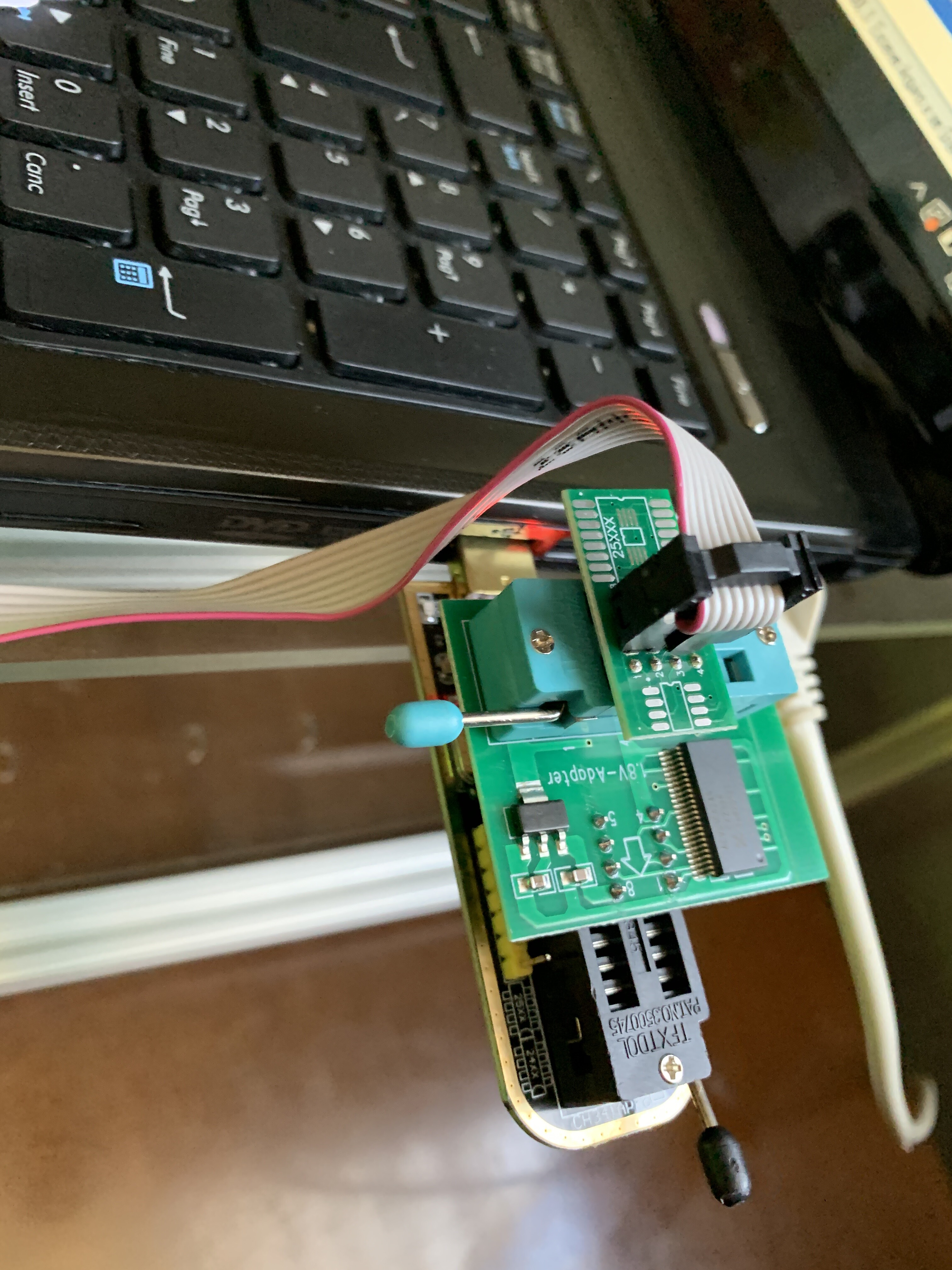
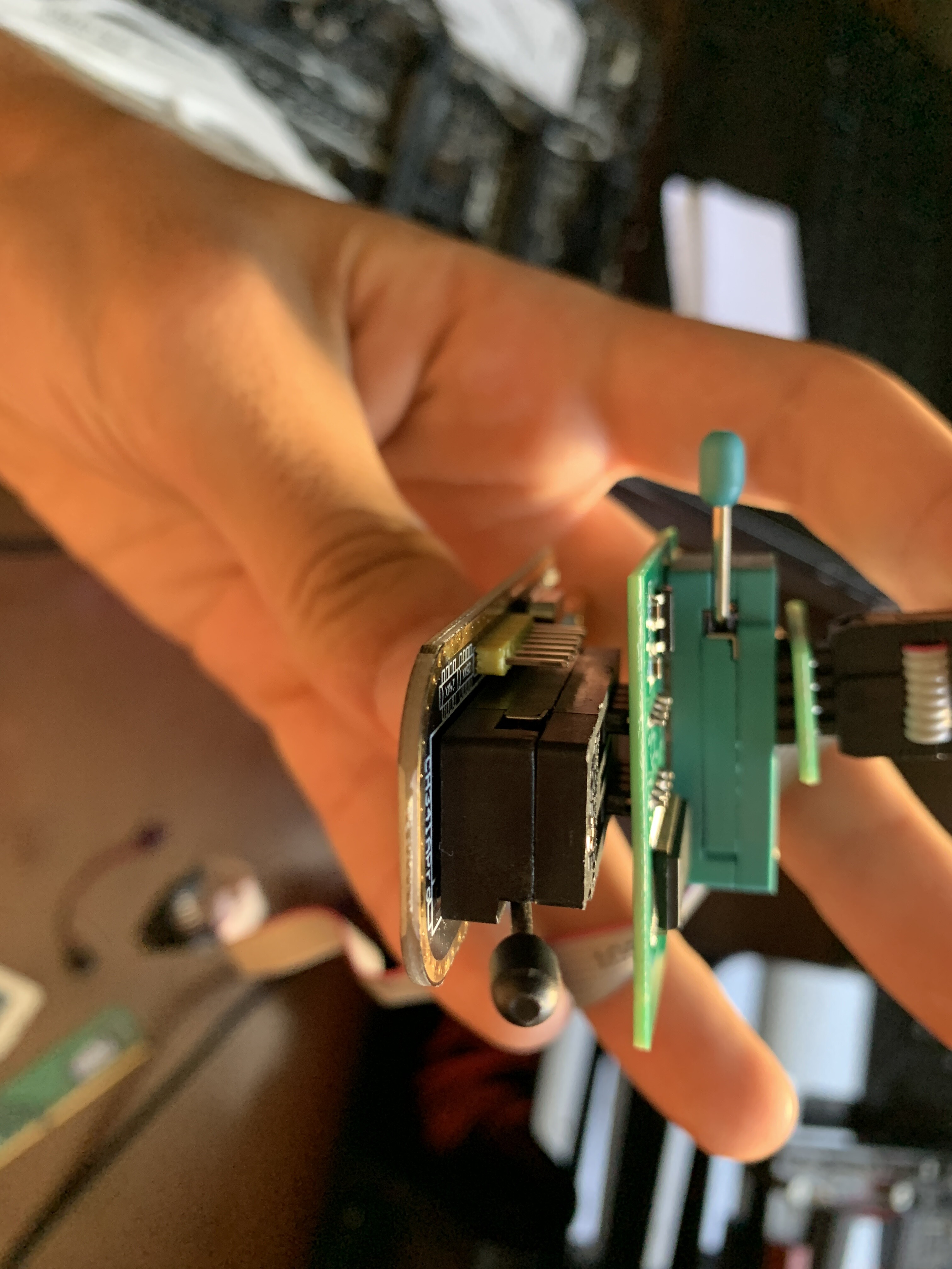
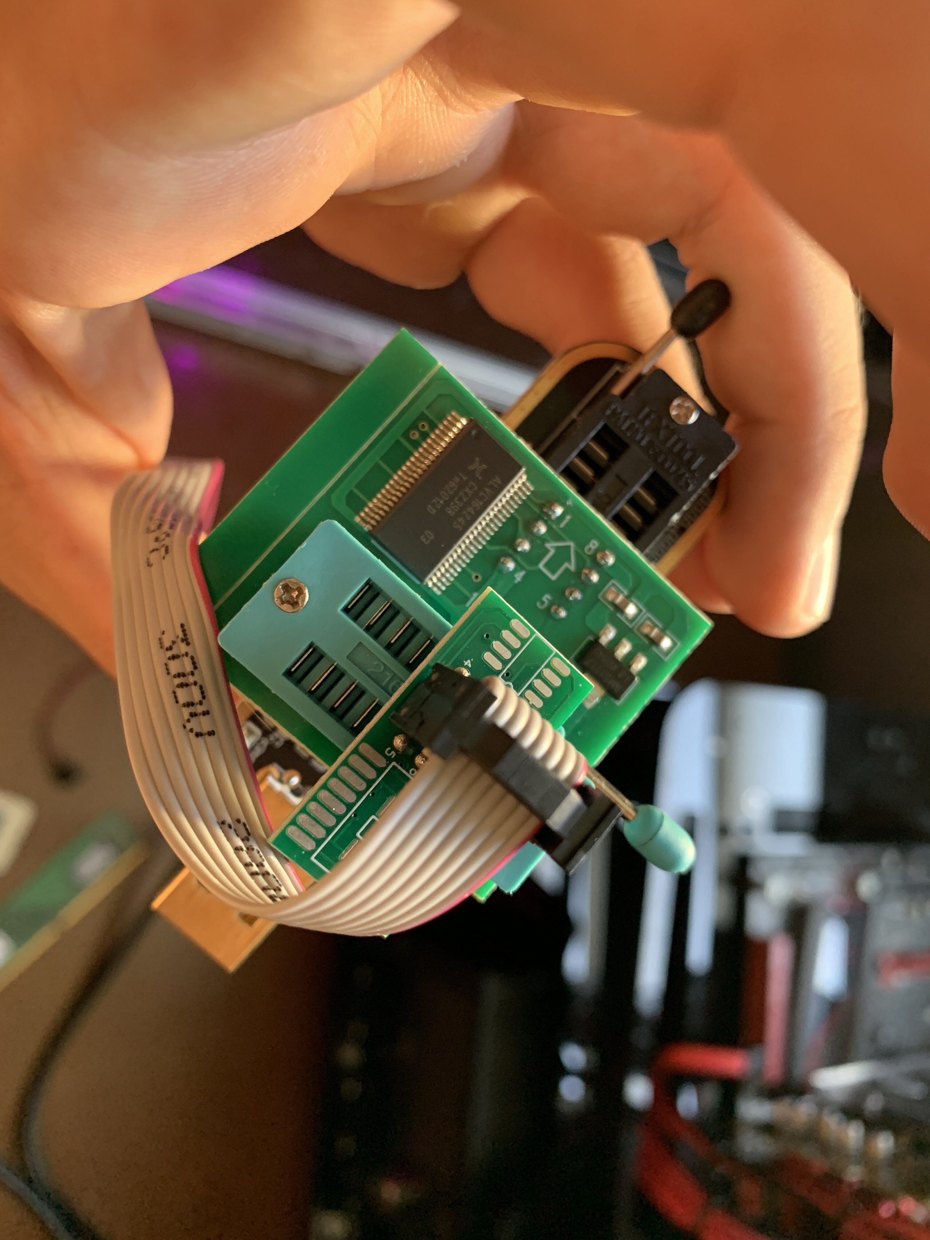
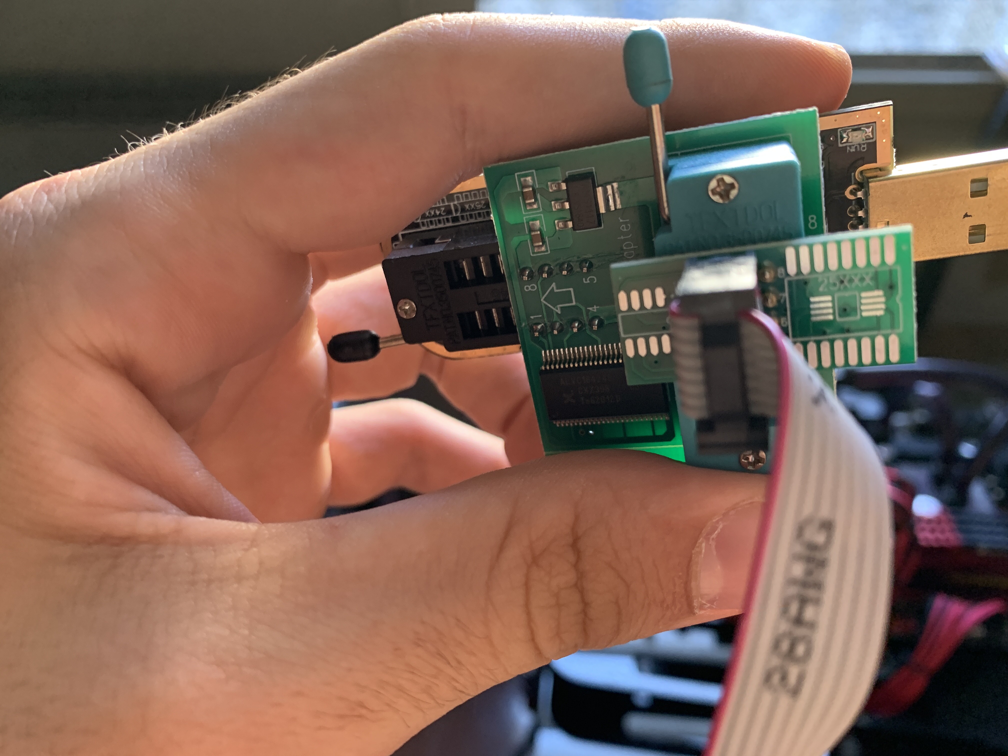
Hey man, my SPI programmer with the 1.8v adapter finally arrived. I assembled it like you can see in the pictures but I can’t detect the Chip. The clip is making proper contact and I’ve tried the programs you suggested.
did you try to unsolder the chip?
@ItxLeo - Looks correct, but I can’t tell for sure if jumper is in correct place on the programmer. I also cannot see if you have red wire on cable going to pin one on the board - please zip all images - thanks
Also, some systems need 24/8 PSU cables connected, others need them removed. And you may need to reclip 10+ times before it’s perfect, looking attached correct to chip does not mean it is perfectly attached, it’s a pain sometimes 
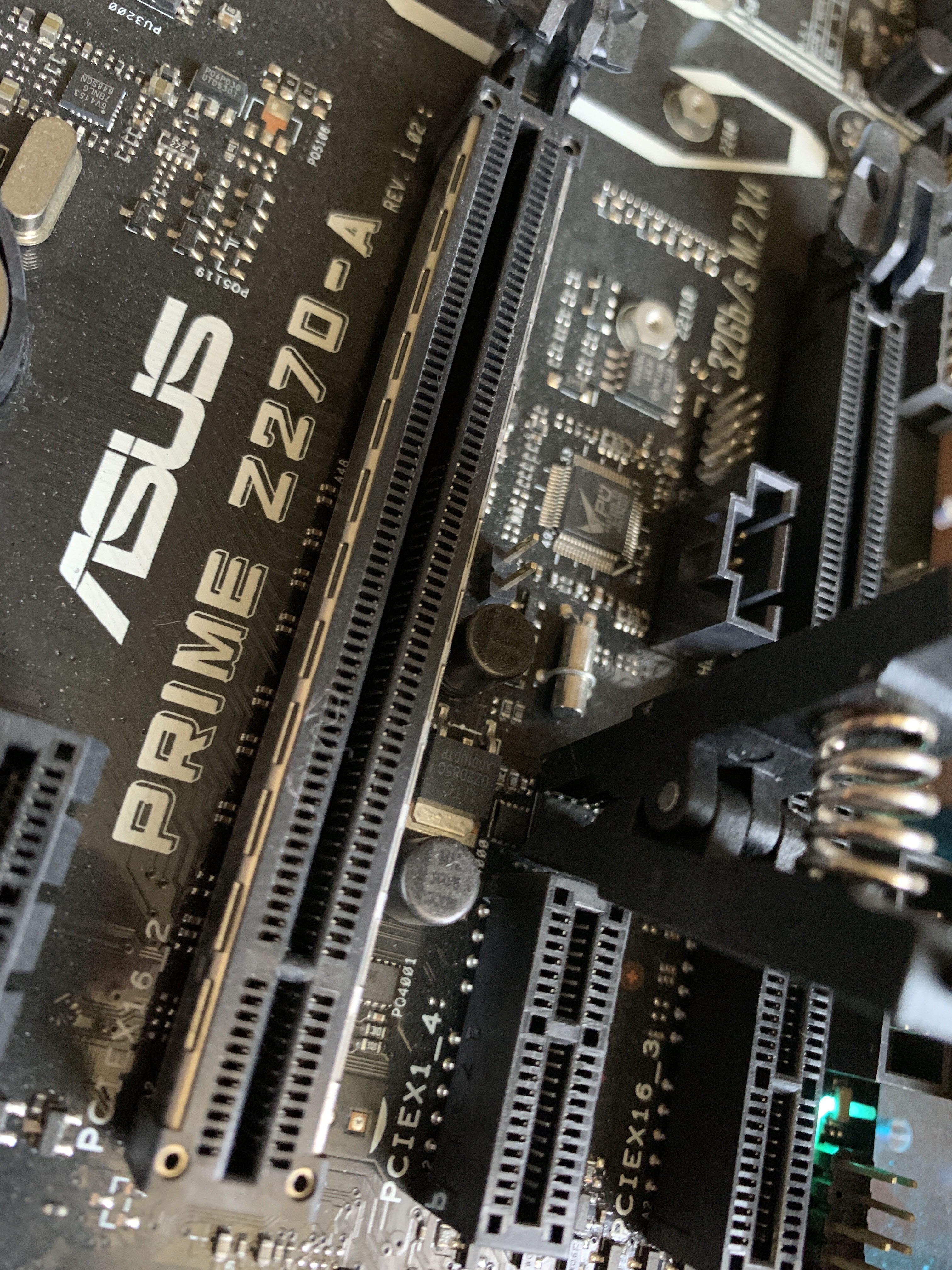
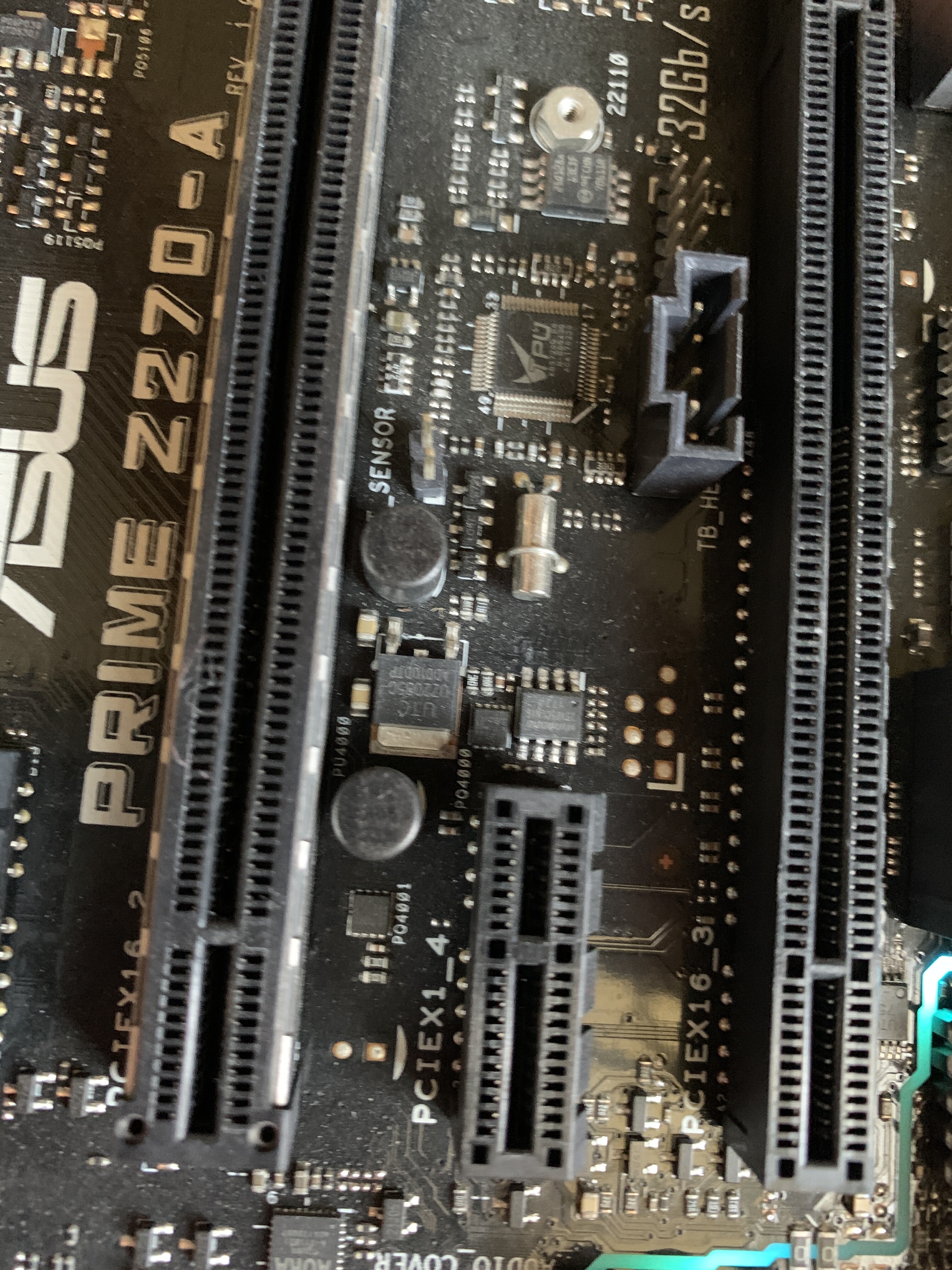
Ohh!! And now I see, you are not attaching cable to the BIOS chip at all! BIOS chip is the other one, to the right of the “TPU” chip, right next to the M2 mounting screw hole
Additionally, I can’t tell for sure, but if that is a 13 in second line on chip ID then it’s a 3V chip and no adapter is needed. Use ASProgrammer. But, since I mention this, please know, software or version used does not have anything to do with chip detection, this only matters to proper read/write functionality.