Here’s a compiled version of flashrom with Ryzen support (https://github.com/tolga9009/flashrom/tree/ryzen). It includes the libpci library so it supports the -p internal flag. It’s possible to compile libpci on Windows using MinGW and DJGPP so I’ve also attached the "libpci-libgetopt" folder with the pre-compiled libraries included so you can compile your own version easily.
Use this to compile it from MSYS:
1
make CC=i586-pc-msdosdjgpp-gcc STRIP=i586-pc-msdosdjgpp-strip LIBS_BASE=../libpci-libgetopt CONFIG_ENABLE_LIBUSB1_PROGRAMMERS=no
I've also included a version of Rufus that will create an MS-DOS boot disk. NOTE: You may need to enable the Compatibility Support Module (CSM) in your BIOS to boot it.
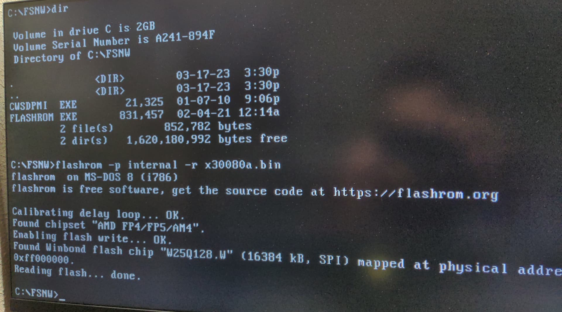
C:\>flashrom -p internal -w X3MSTX_1.70
flashrom on MS-DOS 8 (i786)
flashrom is free software, get the source code at https://flashrom.org

Calibrating delay loop... OK.
Found chipset "AMD FP4/FP5/AM4".
Enabling flash write... Disabling read write protection of flash addresses from Oxfc000000 to Oxfc85ffff failed.
Disabling read write protection of flash addresses from Oxfd000000 to Oxfd05ffff failed.
Disabling read write protection of flash addresses from Oxfe000000 to Oxfe05ffff failed.
Disabling read write protection of flash addresses from Oxff000000 to Oxff05ffff failed.
ERROR: State of SpiAccessMacRomEn or SpiHostAccessRomEn prohibits full access.
PROBLEMS, continuing anyway
No EEPROM/flash device found.
Note: flashrom can never write if the flash chip isn't found automatically.
Can anyone confirm that the above removes protection? Probably best to have a CH341A flash programmer + SOIC8 test clip cable in case it renders system non-bootable.
If you already flashed to a BIOS with AGESA 1.2.0.0 or above you can try to flash to earlier BIOS (pre 1.2.0.0) and clear CMOS and see if flashrom works again. I have not had any luck using this method.
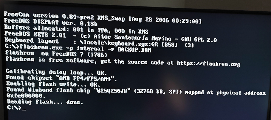
@headkaze : The Flashrom 1.2 Utitlities, which are attached to the start post of >this< thread, seem to work with my ASRock X570 Pro4 mainboard, although the in-use BIOS 4.20 contains the latest AGESA 1.2.0.3 Patch C modules. As you can see here, I was recently able to let the Flashrom 1.2 create a BACKUP of my mainboard’s current BIOS Region:
What I haven’t yet tested is flashing of a modded BIOS by using the Flashrom 1.2 Utilities.
It’s quite possible the new security features don’t inhibit the ability to use flashrom to make a backup of your BIOS and quite possibly you can still write a properly signed official BIOS. The problem is likely only with writing a custom modified BIOS.
@headkaze : Please give us some additional information about your recent python tests while running Linux: 1. What exactly was the sense of your tests? 2. Which conclusions do you draw from the test results? 3. What have your python tests to do with the topic of this thread? Is the usage of python an alternative to the Flashrom tool?
Please put the python results into “spoilers” to save space.
Post #7 tells you the flash protection is SpiAccessRomEn (bit 22) and SpiHostAccessRomEn (bit 23) being cleared in the SPICntrl0 register (sudo python3 chipsec_util.py mmio dump SPI + 0x00). There’s a tool called chipsec which can read and write registers.
First I read the register sudo python3 chipsec_util.py mmio dump SPI + 0x0 which has a value of 0x4F0C2105, then I set bits 22 and 23, which gives 0x4FCC2105 and write this value back. Reading it again gives the original value of 0x4F0C2105. It demonstrates that these "clear-once protection bits" cannot be set again to remove the protection (as expected).
chipsec has finally merged @kerneis-anssi’s amd updates.
So now you can run the following:
1
$ sudo python3 chipsec_util.py reg read SPICntrl0
Which will output something like the following:
1 2 3 4 5 6 7 8 9 10 11
[CHIPSEC] SPICntrl0=0x4F0C2105
[*] SPICntrl0 = 0x4F0C2105 << SPI_Cntrl0. Reset: 0FC0_0000h.
    [18] SpiReadMode[0]   = 1 << Read-write. Reset: 0. Bit[0] of SpiReadMode. See the definition of SpiReadMode[2:1] in this register. SpiReadMode = {SpiReadMode[2:1],SpiReadMode[0]}.
    [21] IllegalAccess    = 0 << Read-only. Reset: 0. 0=Legal index mode access. 1=Illegal index mode access.
    [22] SpiAccessRomEn   = 0 << Read,Write-0-only. Reset: 1. 0=Software cannot access MAC's portion of the ROM space   (lower 512 KB). 1=Software can access MAC's portion of the ROM space. This is a clear-once protection bit. Once set, some SPI registers can't be written and discards a SPI request if it is an illegal request.
    [23] SpiHostAccessRomEn = 0 << Read,Write-0-only. Reset: 1. 0=MAC cannot access BIOS ROM space (upper 512 KB). 1=MAC can access BIOS ROM space. This is a clear-once protection bit. Once set, some SPI registers can't be written and discards a SPI request if it is an illegal request.
    [24] ArbWaitCount     = 7 << Read-write. Reset: 7h. Specifies the amount of wait time the SPI controller asserts HOLD# before it should access the SPI ROM, under ROM sharing mode with the MAC. This time is to allow the MAC to sample HOLD#.
    [27] SpiBridgeDisable = 1 << Read-write. Reset: 1. Setting this bit disables the SPI bridge mode (SB acts as a SPI-LPC bridge to the MAC).
    [28] SpiClkGate       = 0 << Read-write. Reset: 0. 1=Skip the 8th SPI clock at the end data when doing read.
    [29] SpiReadMode[2:1] = 2 << Read-write. Reset: 0h. Description: See Table 78 [SpiReadMode[2:0]]. NOTE: SPI modes supported are listed below,
    [31] SpiBusy          = 0 << Read-only. Reset: 0. 0=SPI bus is idle. 1=SPI bus is busy.
Now you can clearly see that SpiAccessRomEn and SpiHostAccessRomEn are both set to 0. This means the BIOS ROM space is protected.
@DarkPoe the only way around this would be to remove the appropriate modules from the BIOS before upgrading as mentioned in my previous post.
I have yet to hear if anyone has done this successfully.