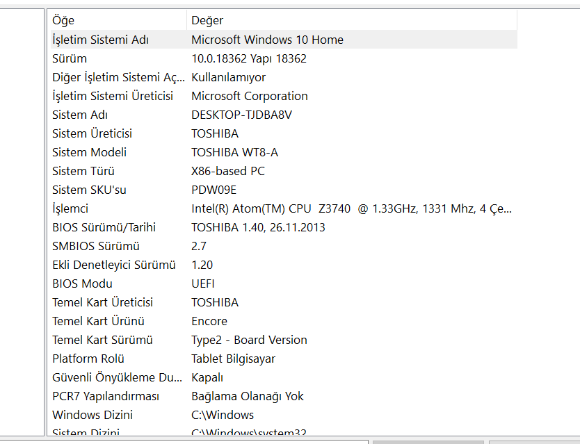
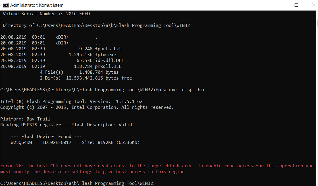
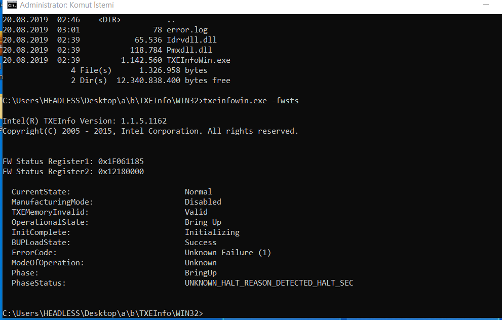
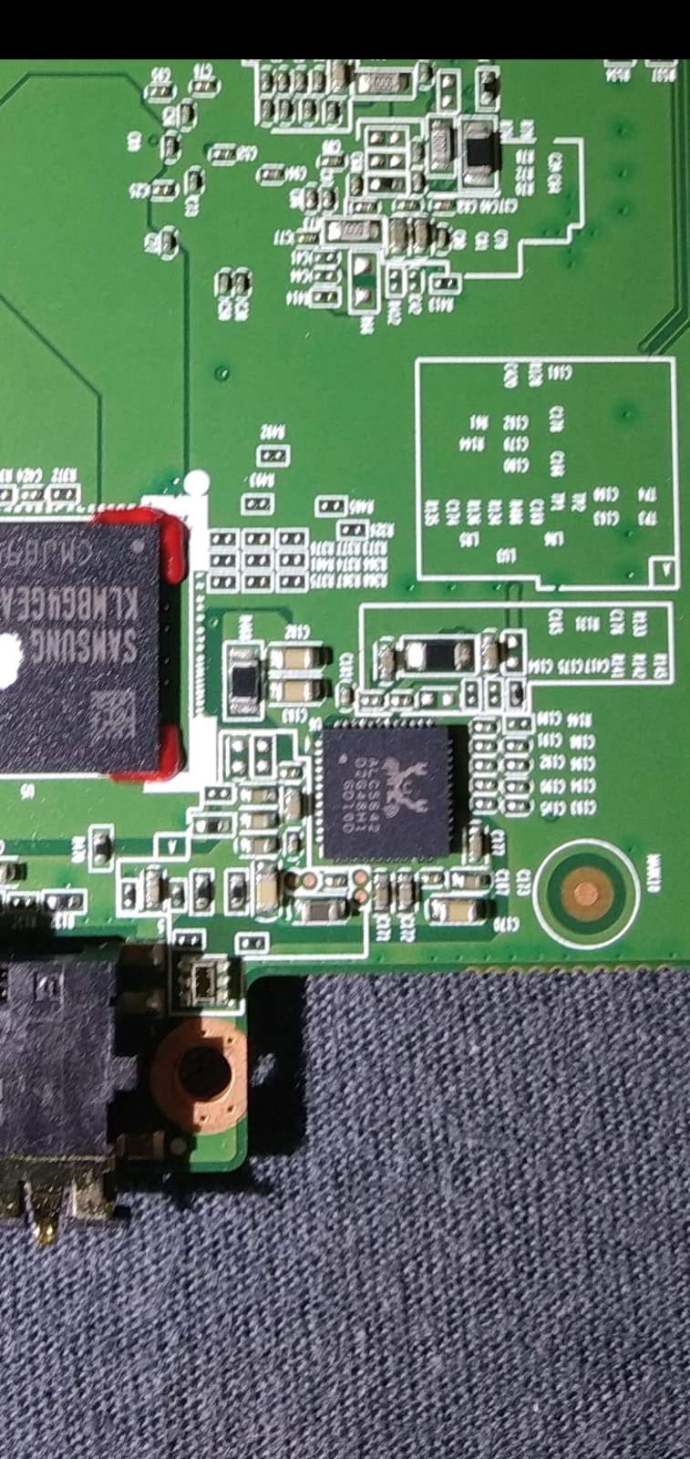
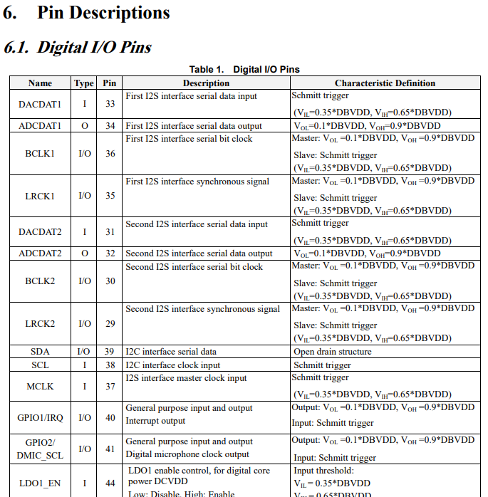
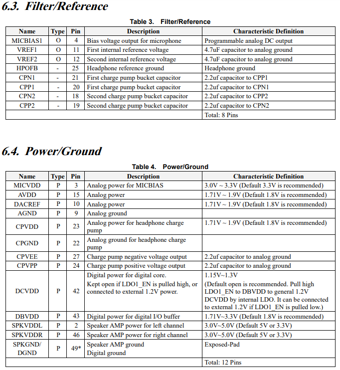
hi, everyone I have toshiba Encore WT8-A (PDW09C-00101L) windows tablet. And it shutdown every 30 minutes. I find this forum that someone can help me especially @plutomaniac this guy. I am stuck. I attached necessary files. I can perform pin-mod methot. But what I am going to do after that. audio chip part number ALC5642
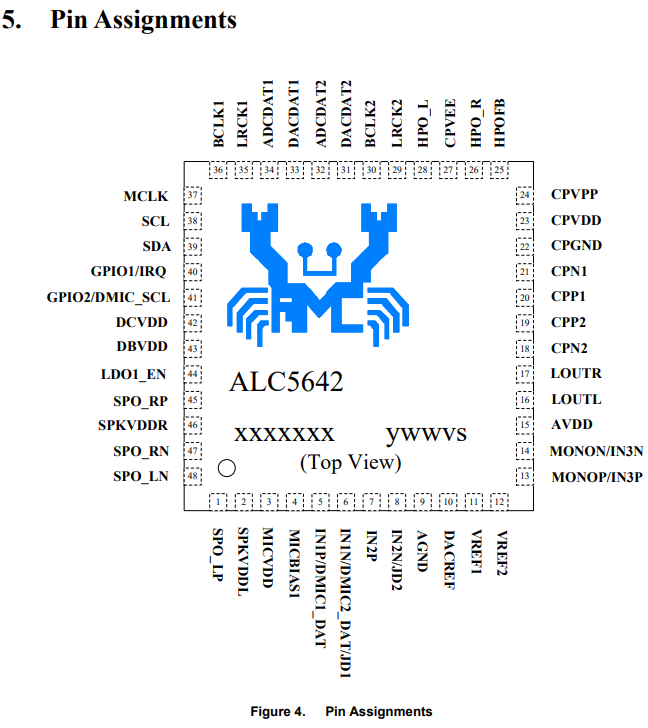
The difficult part is to unlock the FD. I found a datasheet for ALC5642 (attached) but its pinout is different from the common Realtek chips we encounter.
It is definitely not pin 1 and 5 for example. Maybe pin 39 and 42 or 43? I’m not sure. If we cannot be certain, I strongly suggest that you do not try the pinmod to avoid frying the audio chip. In such case, do you happen to have a programmer to dump the SPI chip that way?
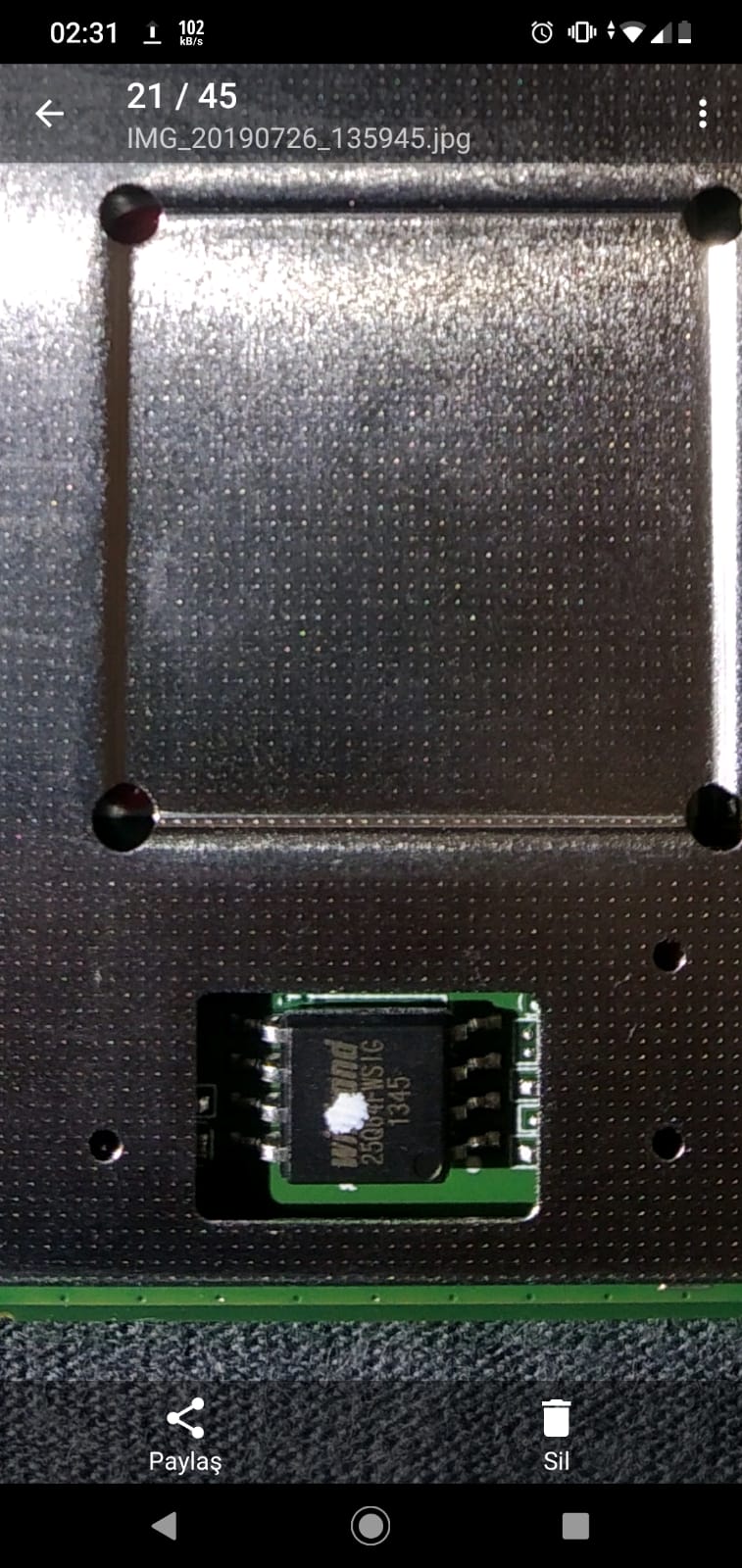
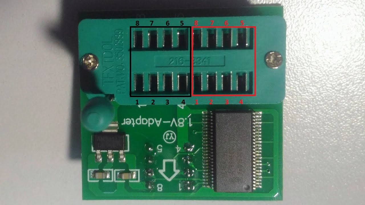
That’s an 1.8V SPI chip. I guess a CH341A programmer with a SOIC8 clip and an 1.8V adapter will be required but @Lost_N_BIOS knows these things better.
25Q64FWSIG will need a 1.8V adapter to work with CH341A programmer. I have the CH341A, TL866CS and SVOD3 programmers. Only SVOD3 doesn’t need adapters.
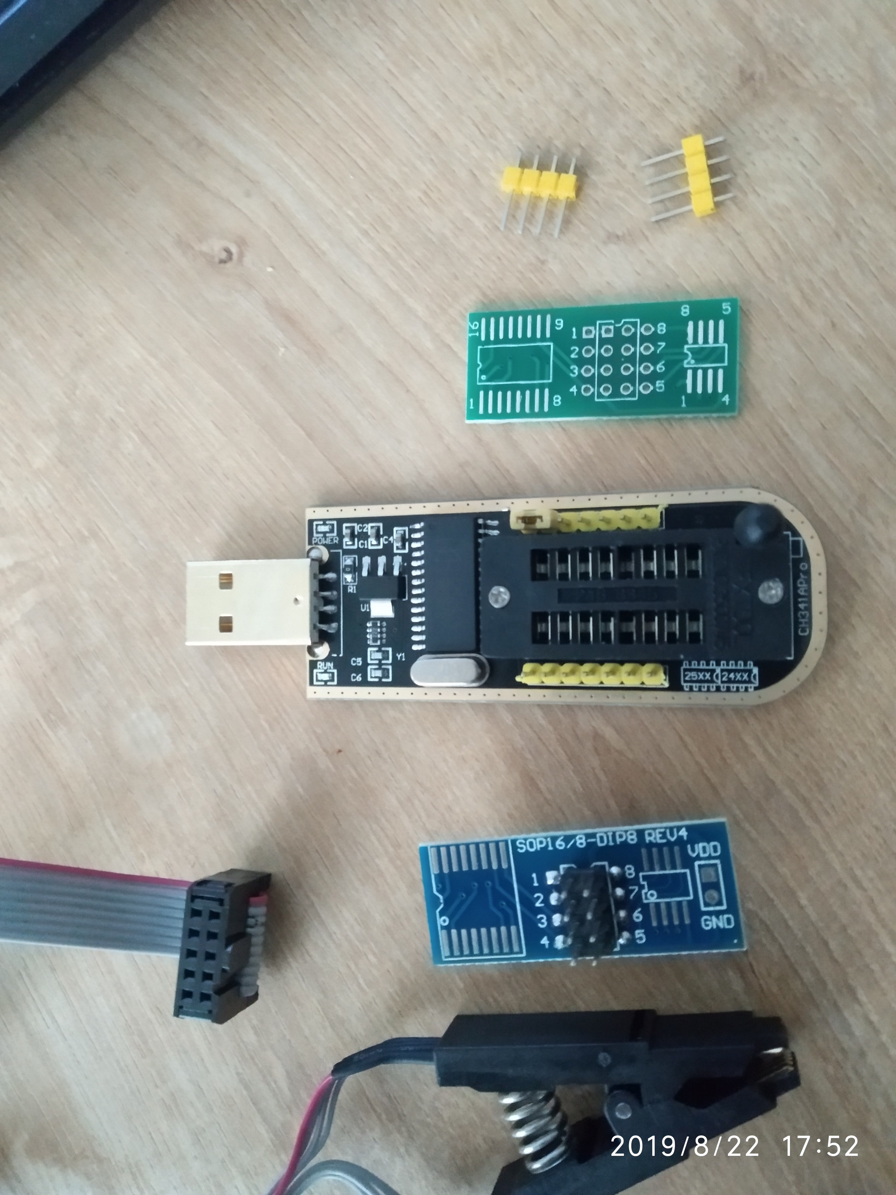
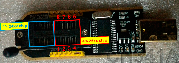
Yes, you need CH341A + SOIC8 Test clip w/ Cable + 1.8V adapter. No soldering is required. All very cheap if you order from China and wait 3-5 weeks, if you need it fast then price will double or triple from local sellers or other places that ship faster Here is general examples so you know what you are needing to purchase, you can get kits or combos on ebay that have all this in one listing too. https://www.ebay.com/itm/332735579991 https://www.ebay.com/itm/382486015977 << On this, with other non-kit/combo listings, be careful and make sure listing says comes with cable, some listings will be selling clip only but show cable too in their images. https://www.ebay.com/itm/202046860676
Yes, FD can be unlocked and ME FW fixed in few minutes with programmer. When it arrives, slow down, wait for help/advice, just be sure you do not erase or write to chip until you’ve made a backup and had someone check it to confirm it’s good, otherwise you can loose your board specific info like serial, UUID, LAN MAC ID etc. When it arrives I can help you as needed. Here is general software and main driver - http://s000.tinyupload.com/index.php?fil…257455007472602
And here is how to use guide, this does not have adapter shown in it, I’ll have to see if he can update with adapter info too if he has (PM Sent). Basically, you will put adapter into programmer the same way you would a cable or chip, then your cable will go into adapter on top [GUIDE] Flash BIOS with CH341A programmer https://www.bios-mods.com/forum/Thread-G…341A-programmer << Same as one directly above, but with all images expanded/visible at once
Main thing to do once you have it working and detecting you chip is to get a backup made, upload that for someone to check, then wait and do not try to move forward until someone says OK GO
hello again. I got programmer and clips but not 1.8V adapter. Do I really need the adapter. Do we need this adaptor because of not de-soldering the chip from MB. İf so, I can remove it completely or just VCC and Gnd pin
That was fast. However, the CH341A supplies 3.3V so you’ll fry your SPI chip if you don’t use an 1.8V adapter. You’ll use the SOIC8 cable+clip to avoid desoldering.
Yes, you need 1.8V adapter as mentioned above. Chip can survive 3.3V usually, unsure for how long, but I do know data is corrupted on read and write always when this is attempted, if/when it does detect the chip and allow it, so you really have to get the adapter.
If you do know how to safely do lead free desoldering, then you could remove that chip and replace it with another same sized one you have spare or from a dead board. If you are not familiar with lead free desoldering and do not have a good soldering station setup (ie not a cheap solder pen without high wattage and temp control) then it’s best you don’t do this because you can easily damage the board by destroying a pad or lifting a pad trying to get it hot enough to release. You’d also probably damage the chip legs, during all this, if you are not familiar with removing such items put on with lead free solder, it’s hard to keep them all hot enough at once to lift without trashing the legs. Same applies with hot air, less chance you’d damage a pad by lifting it off due to too much heat for too long, but you can still damage pads or traces trying to do this if not familiar too.
Either way (solder or hot air), if you try it, in order to put on a different chip, please add lots more leaded solder first and plenty of flux, it will help release the lead free solder. Tough to explain, and I probably shouldn’t give advice like that without a huge guide explaining how all that works, but I know some people jump right in anyway so I wanted to give you some info to help release it if you tried. At least that way if you jump, maybe knowing that will help you lessen chances of ripping the pads off the board due to being too cold or you think it’s hot enough it should release and you try to force. Lots more leaded solder And flux will get things flowing, but you do need a good high wattage solder setup or the board will suck all the heat right out of your solder tip and point of contact will never heat up to proper temps to release anything.
Best to use another system until your adapter arrives!
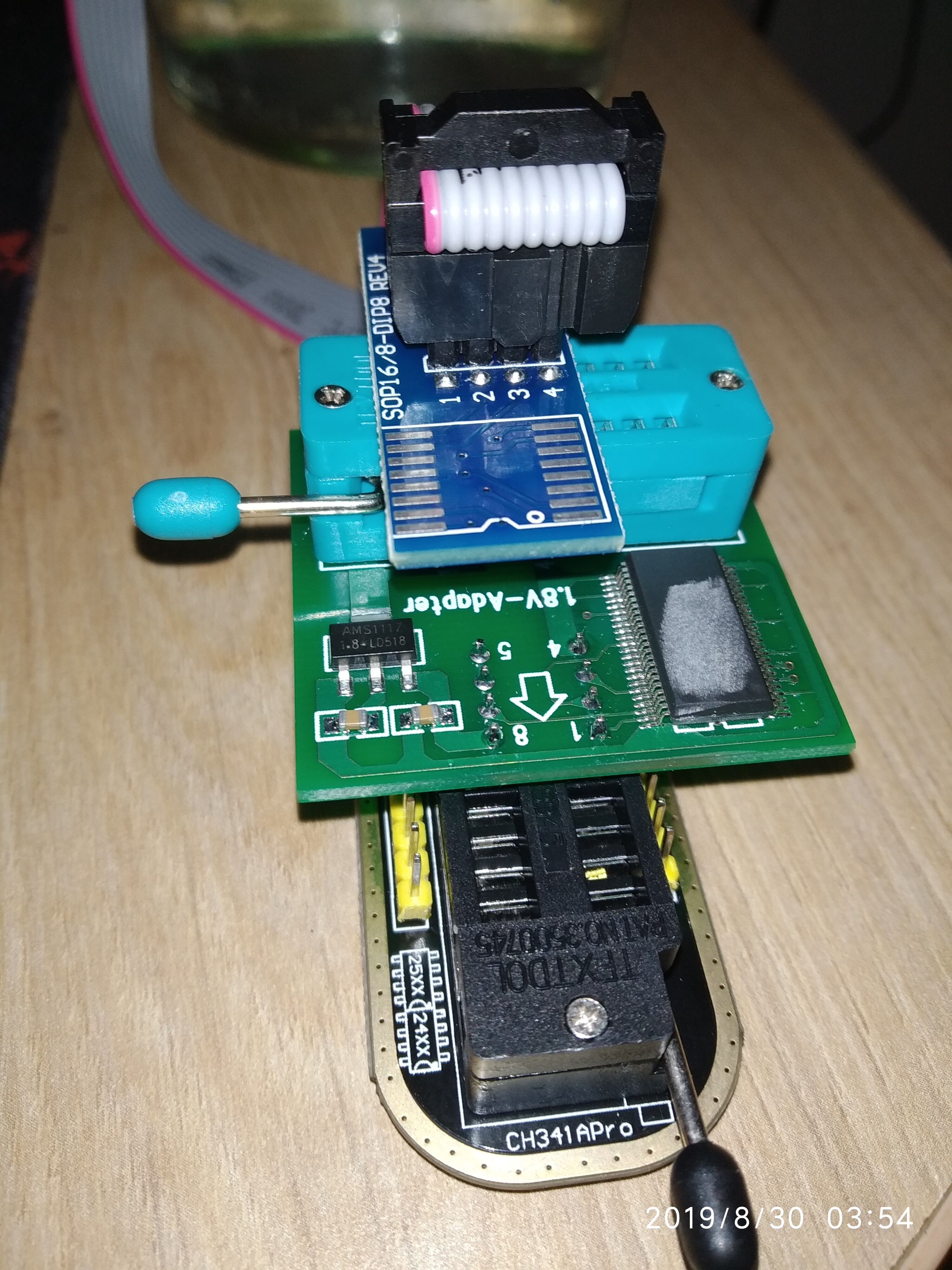
Hello again, I got 1.8v adaptor. But how we combine all these. 1.8V adaptor socket pins are the same with CH341A programmer? I connect them like this. Is that correct? then what we do next? @plutomaniac , @Lost_N_BIOS
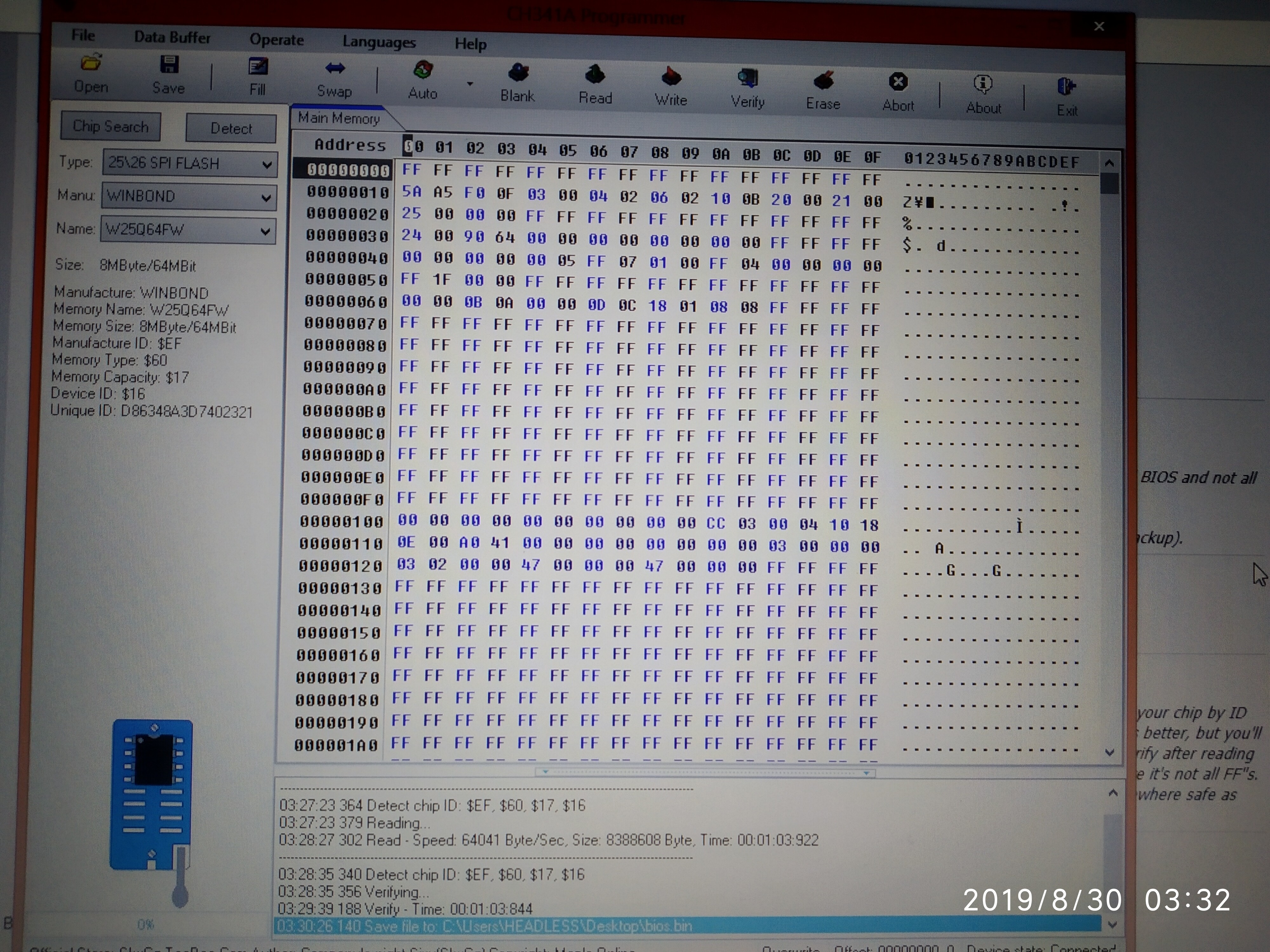
@HEADLESS - It looks like you have it all connected correctly… And BIOS looks OK!
Here is fixed BIOS with latest fixed ME FW, with unlocked FD in case you run into issues in the future this will help you reflash via FPT without having to use programmer every time. http://s000.tinyupload.com/index.php?fil…325435493401726
@HEADLESS - Sorry for not saying, yes, please go ahead now and erase chip, blank check, then open the BIOS I sent you, then write/verify.
Then remove power cable from board if not already, leave board sitting for 1+ minute without any power. Press and hold the power on button for 10-15 seconds, or short pins. Then connect power, hook everything back up and boot to BIOS and load optimal defaults, then make any changes you need and save and exit.
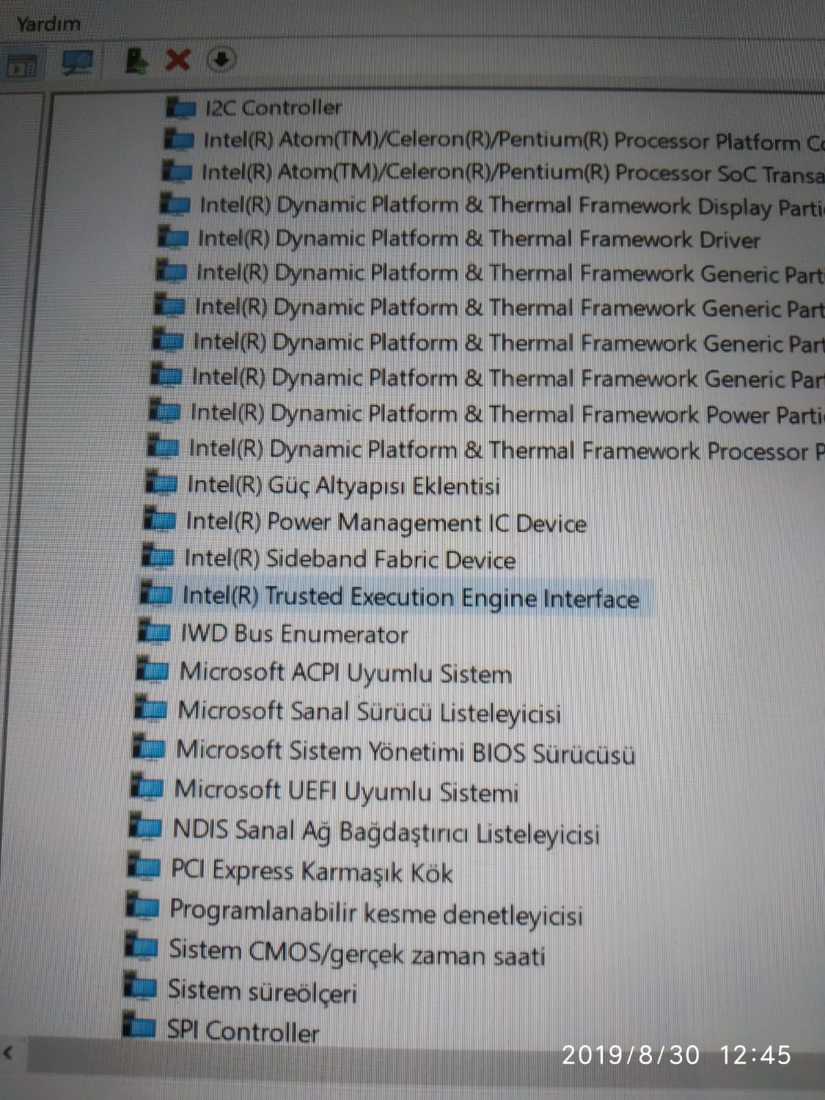
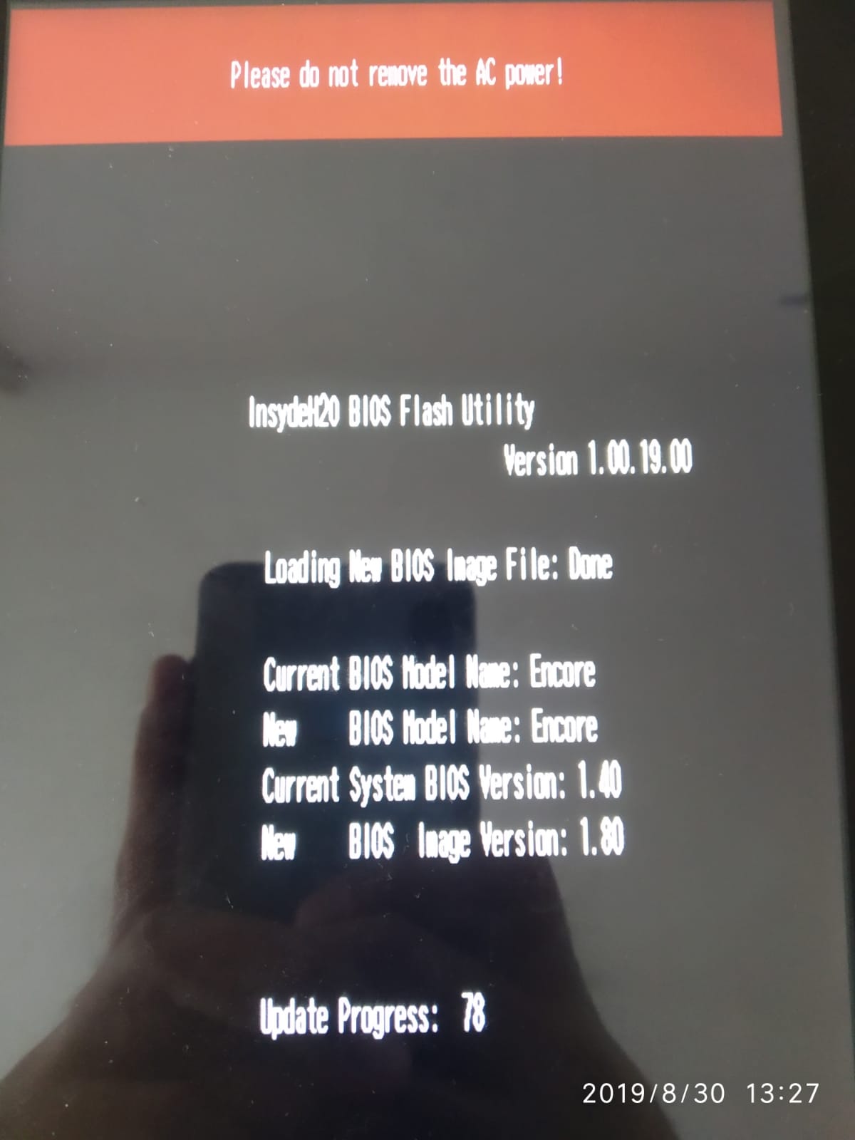
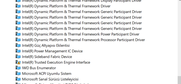
WE DID IT. I erased and wrote your file sent me before. there is no shutting problem anymore. there is no exclamation mark on TXE driver. After fixed, tablet let me update the bios versiyon from 1.40 to 1.80. Every things working fine. THANK YOU SO MUCH. But How did you fix the file I sent you. Please share us @Lost_N_BIOS


 WE DID IT.