Hi,
I am trying to unlock my bios. But it just doesn’t want to unlock.
Msi gt72vr 6re 267be. Ms1785. cpu: i7 6820hk, gpu: gtx1070
Things i tried,
1) Set all menus in amibcp to user: nothing
2) Set all menus in amibcp to supervisor: nothing
3) Modify the setup.ffs, all things from true to false with hx editor: nothing.
4) Trying all tutorials i can find. (not all but many): nothing
(I now the menus are nested)
I have followed many tutorials, but none of them worked. Not a single menu has become visible.
And that code of 01 01 00 01 01 01, is nowhere to be found. My setup strings aren’t there, in my setup module. Searched with hx editor
I think it has something to do with that amitse module, but there is no tutorial for. And out of my comfort zone.
(bios lock is of.) and i have the 4key code for admin mode, but the menus i want are not there.
My problem is my power limit of my cpu, max45tdp. If the gpu is under load while gaming. And it is lagging as hell.
I have spent already one and a halve month trying to unlock the bios, without success.
And the Imon scaling feature doesn’t work for bypassing my power limit.
To flash the bios, I used intel fpt in dos, command: fpt -f bios.bin -bios –rewrite and without -rewrite.
All help is welcome.
link: https://drive.google.com/drive/folders/1…yka?usp=sharing
Please attach a dump from FPT using >> FPT -bios -d biosreg.bin
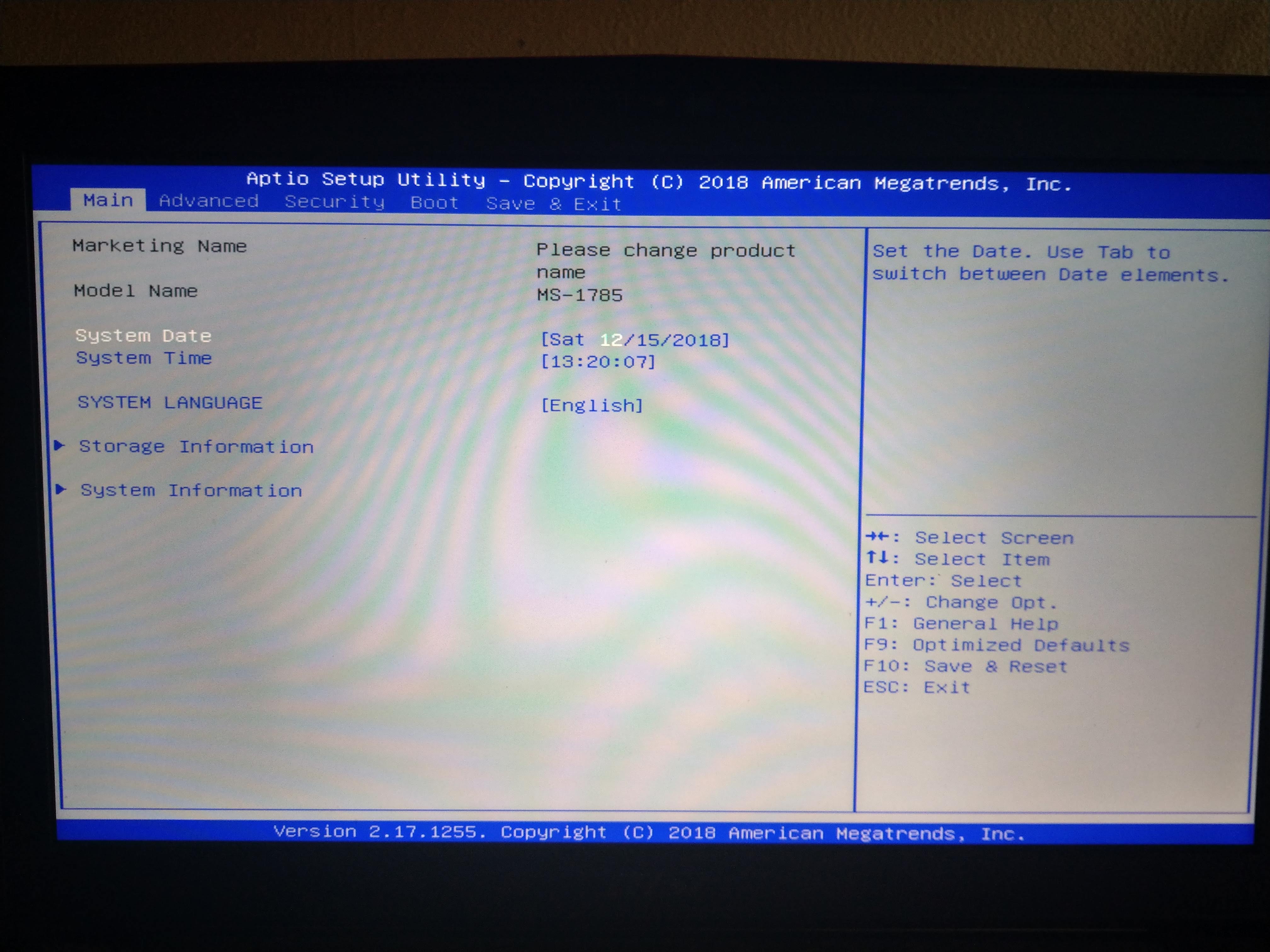
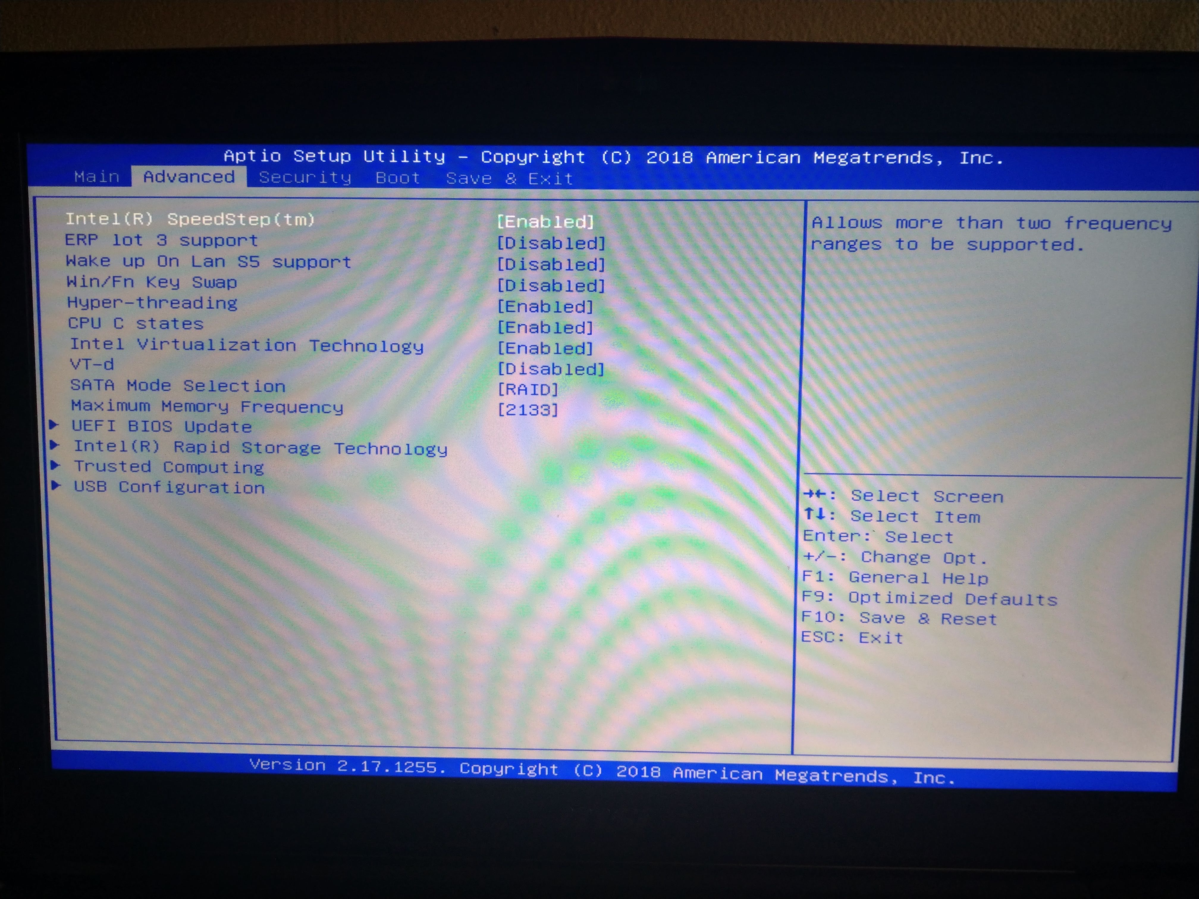
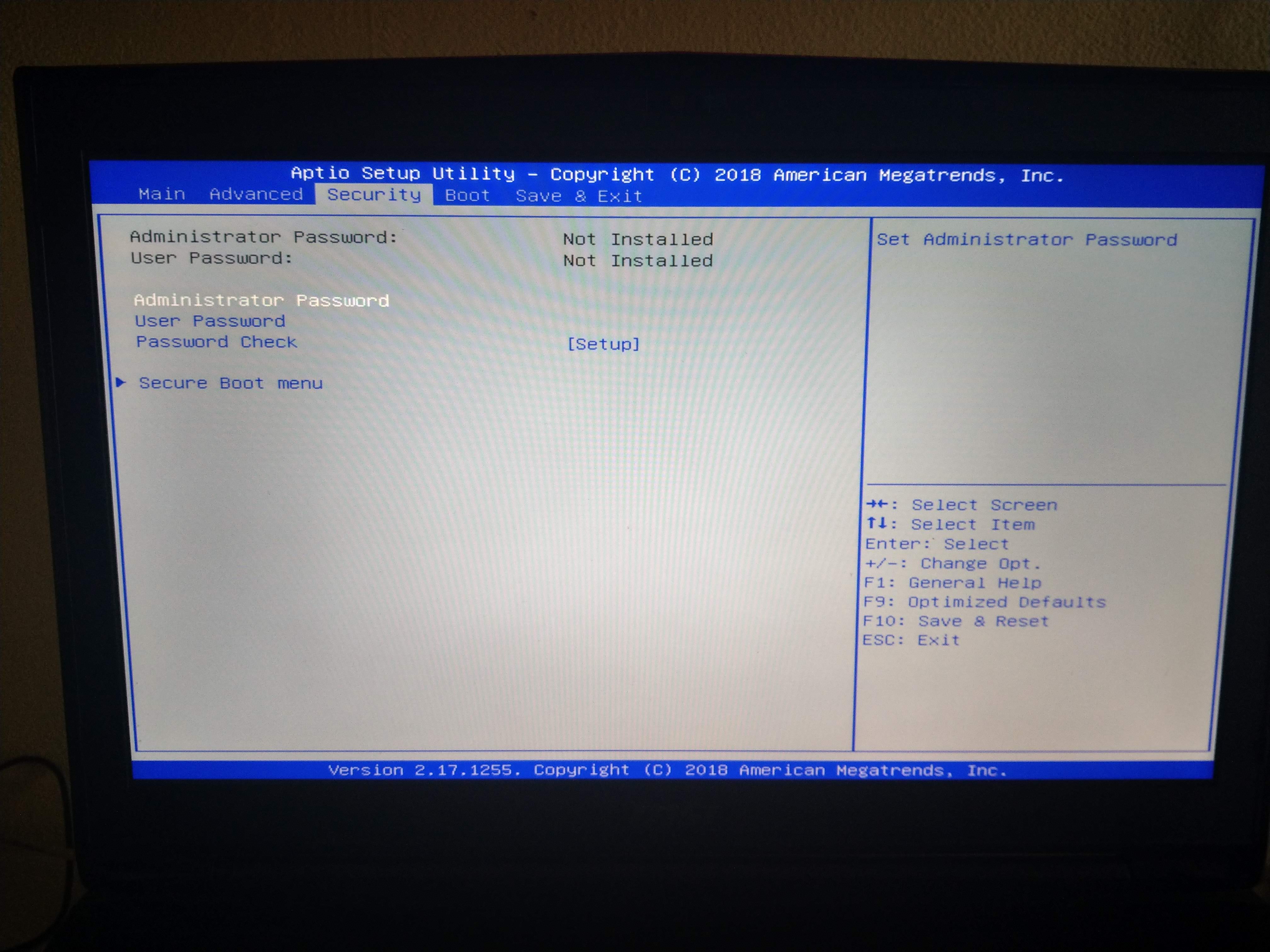
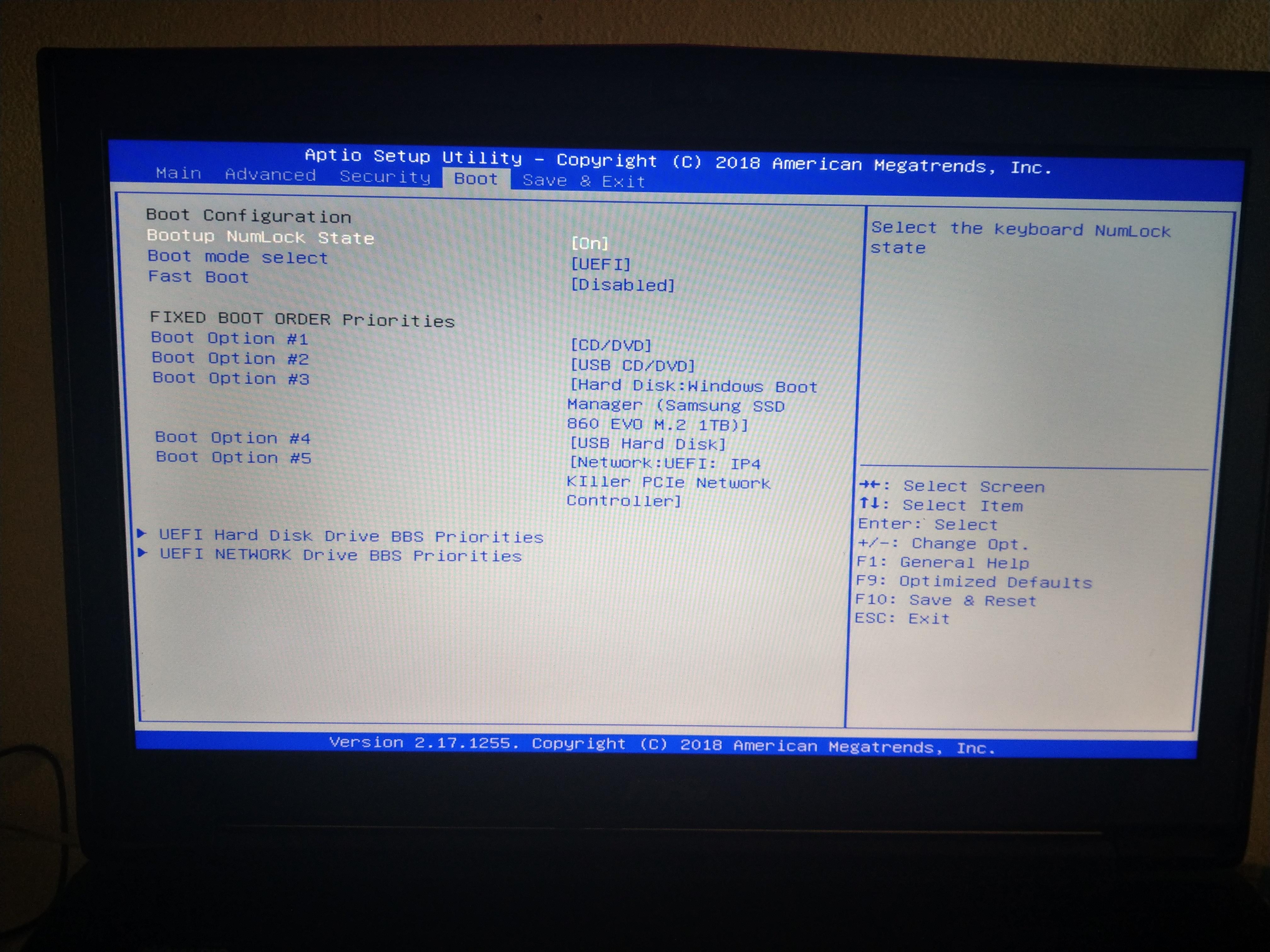
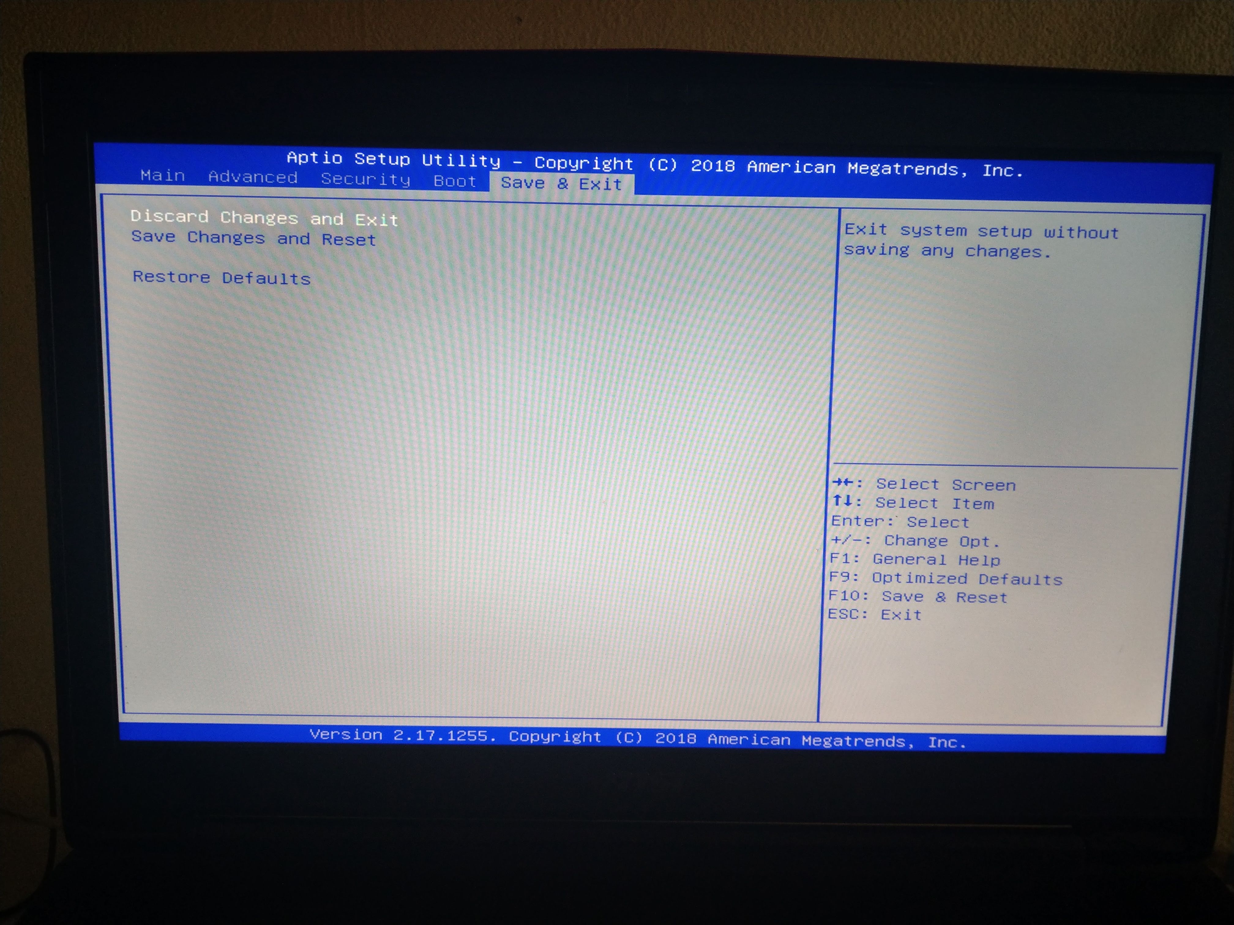
I’ll look into this for you tonight. With the above, please include images of your default BIOS, showing at least one that shows all visible main sections, and then more images showing root entries of Main, Advanced, Security, Chipset if you have it, boot and save and exit.
Sorry, didn’t saw your post yesterday. i think all things you need are attached. I don’t have a chipset menu in my bios. In amibcp there is one, but it’s not showing in the bios menu. And i didn’t understand what you meen with images, so i took pictures of it. the stock bios is in it to. with my modified biosses. I hope you will find something.
Good luck,
Stefan.
biosreg.zip (3.1 MB)
bios default image.zip (3.09 MB)
Official MSI bios form site.zip (5.04 MB)
Thanks, I think you covered all images I asked about, sorry for any confusion but not sure what confused you since you got it  .
.
Are those taken with stock BIOS, or your AMIBCP edited one? If not stock, please retake the images after you reflash stock BIOS as mentioned below (And put new images in a zip) Maybe that’s what was confusing?
Please explain, what is “BIOS Default” file? Is this stock BIOS flashed to your board, then extracted via FPT?
If not, please do that, flash in stock BIOS, and run FPTw command again I gave above, and send that file. I see biosreg.bin I asked for is your AMIBCP edited BIOS, wow that is a lot of “USER” 
I will get into this tonight
Hi, English is not my native language. i was thinking about rom images with different entries. now i get it. it where pictures. ‘‘default bios’’ is my bios image extracted from my official bios.
I didn’t now what a biosreg was, now i now that it is a regular dump of my default bios. Now i attached the good biosreg dump. dumped after the stock bios flash.
The images are taken with the stock bios flashed, but a modded bios is 100% thesame as the pictures taken above.
And yeah, a lot of user, a have a differet one just the same, but all set on supervisor. I now the menus are nested, so i thought why not set them all on user or supervisor, but that didn’t work either.
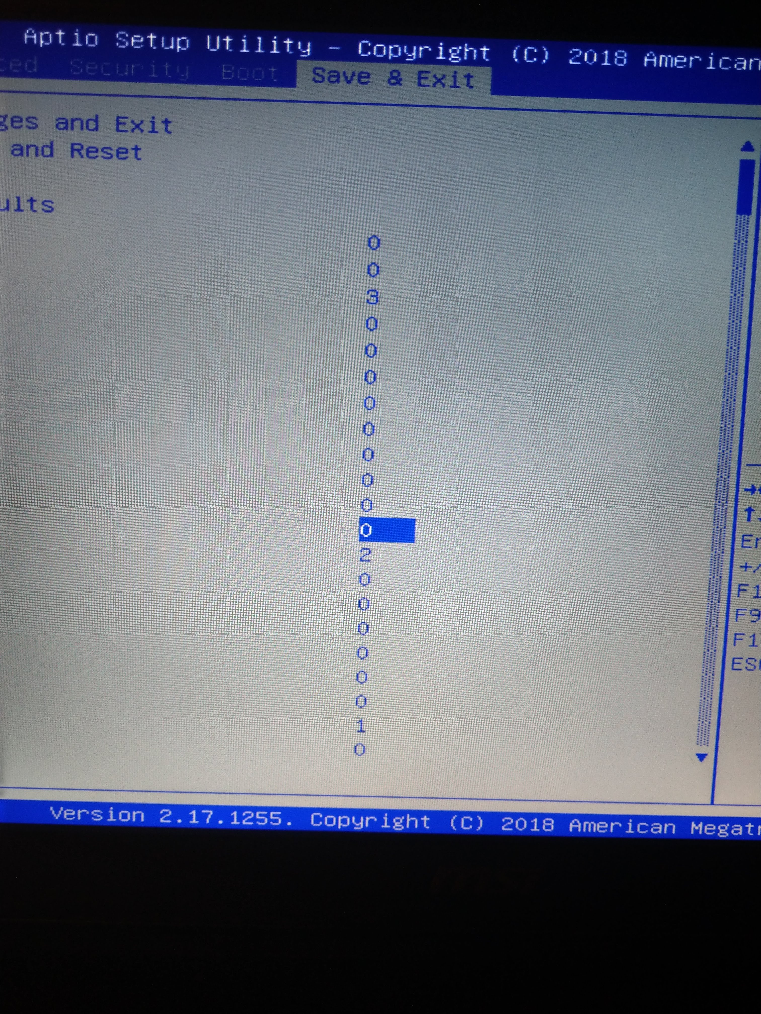
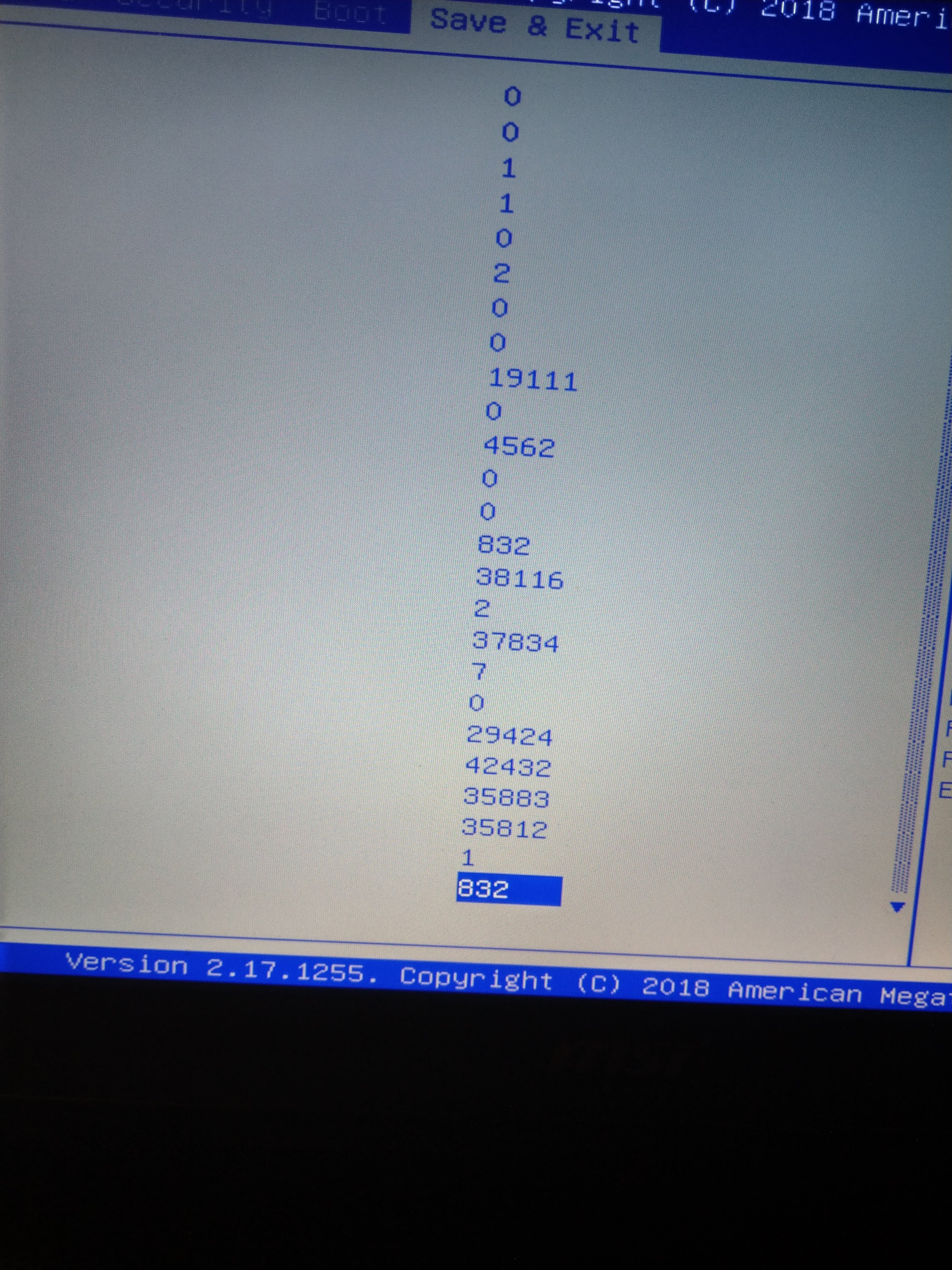
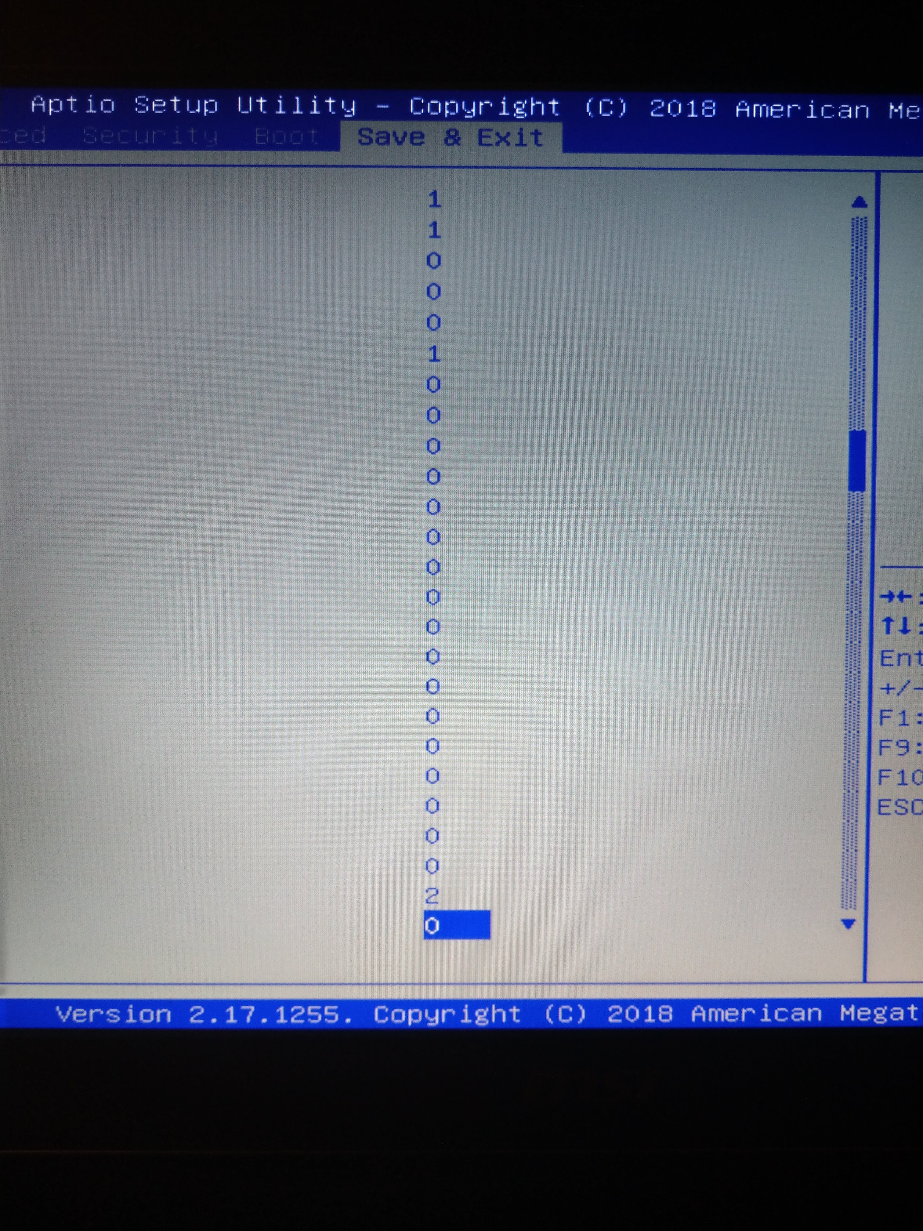
After that i managed to change some things in the setup.ffs extracted from the setup module, i changed all the 46 02 to 47 02., after the flash nothing changed, but in save&exit there where a lot of numbers in a line going downwards. just irregular numbers.
Like this:
1
5479
26
479
52
65
2
. but all on the right. just something weird.
Thats all i can tell you, hopefully you will find something.
I gave up. This is all new for me, and it was driving me nuts!
But, have a good day!
Stefan.
biosreg.zip (3.1 MB)
@stefanr740 - It’s OK, we will get to understanding each other! When I said I need pictures of your default BIOS, I mean images/pictures of the BIOS that has not been edited at all by you, so default non-edited BIOS images.
No, nothing needs extracted from your BIOS, I mean take screenshot (F12) if you can, or use camera. Thanks for confirming, images are the same no matter what, so it’s OK, then I will use those images you already provided.
BIOSreg how I put it, is a dump from your “BIOS Region”, this is main part of BIOS image, without FD, GbE, or ME Regions.
This is usually best way to modify for a few reasons, one your dumped bios region contains all your board specifics like serial, UUID etc, so that will remain in place no matter how you reflash.
And second reason, this region of the BIOS is usually not locked to write to, or when it is that lock can usually be disabled.
You can’t blindly change 4602 to 4702 in mass, causes too many problems as you noticed
So, I can start on stock BIOS. Please flash in stock BIOS again, and then make FPT dump of BIOS region >> FPT -bios -d biosreg.bin
I do not want an edited BIOS dump, that is why I ask please reflash stock BIOS from MSI using normal method they provide, then dump BIOS for me using above command.
So I ask please do this, and then attach new clean dump, this way I know I get stock never edited BIOS region dumped from your system using MSI
Hi, i did all what you said, here is your clean biosreg dump.
Stefan.
biosreg.zip (3.1 MB)
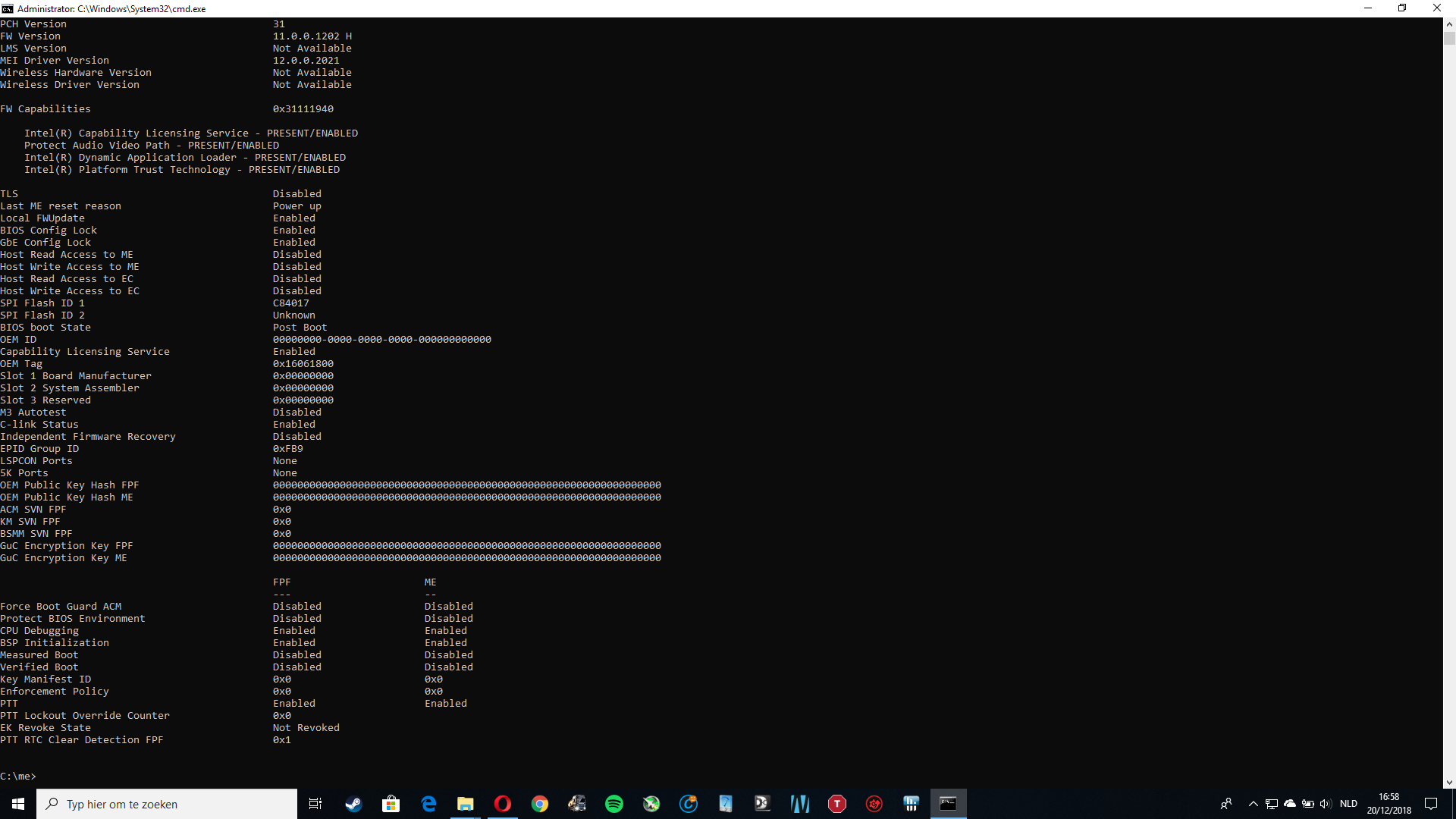
Please run MEInfoWin and post an image of the bottom of the report, need to see if Measured/Verified Boot are enabled at FPF side (Left) BootGuard might be enabled, maybe that is why none of your changes had effect?
And can you dump ME? If yes, please dump and upload >> FPTw.exe -me -d me.bin
Chipset is removed from BIOS totally (Blank chipset form in setup IFR, and AMIBCP chipset menu empty) So no chipset menu can be used on here, would could enable probably but it would be empty.
Only settings you see in AMIBCP or setup IFR output can be used. I will have two BIOS for you quick test on that OC menu here in a second, only meant as a quick test for us to see if two methods can enable that OC menu or more changes are required.
Look for that edit shortly
*Edit @stefanr740 - here is three BIOS, please test each and let me know if you see OC menu and if yes what’s in it for each one. If you see on first test BIOS, please continue and test all three anyway, need to know report from all three tests.
http://s000.tinyupload.com/index.php?fil…249306951336505
Flash via FPT >> FPTw.exe -bios -f filename.bin
After flash, reboot and load optimal defaults, then apply and boot back to BIOS and see if you see OC section or not.
This is not meant to enable that section fully or anything like that, only a quick test of three methods to let me know which if any works for your system and which way is best to move forward
Also let me know if none of these work, other method is required - Thank you for testing all three!
Hi, here is the MEinfoWin result. Picture included.
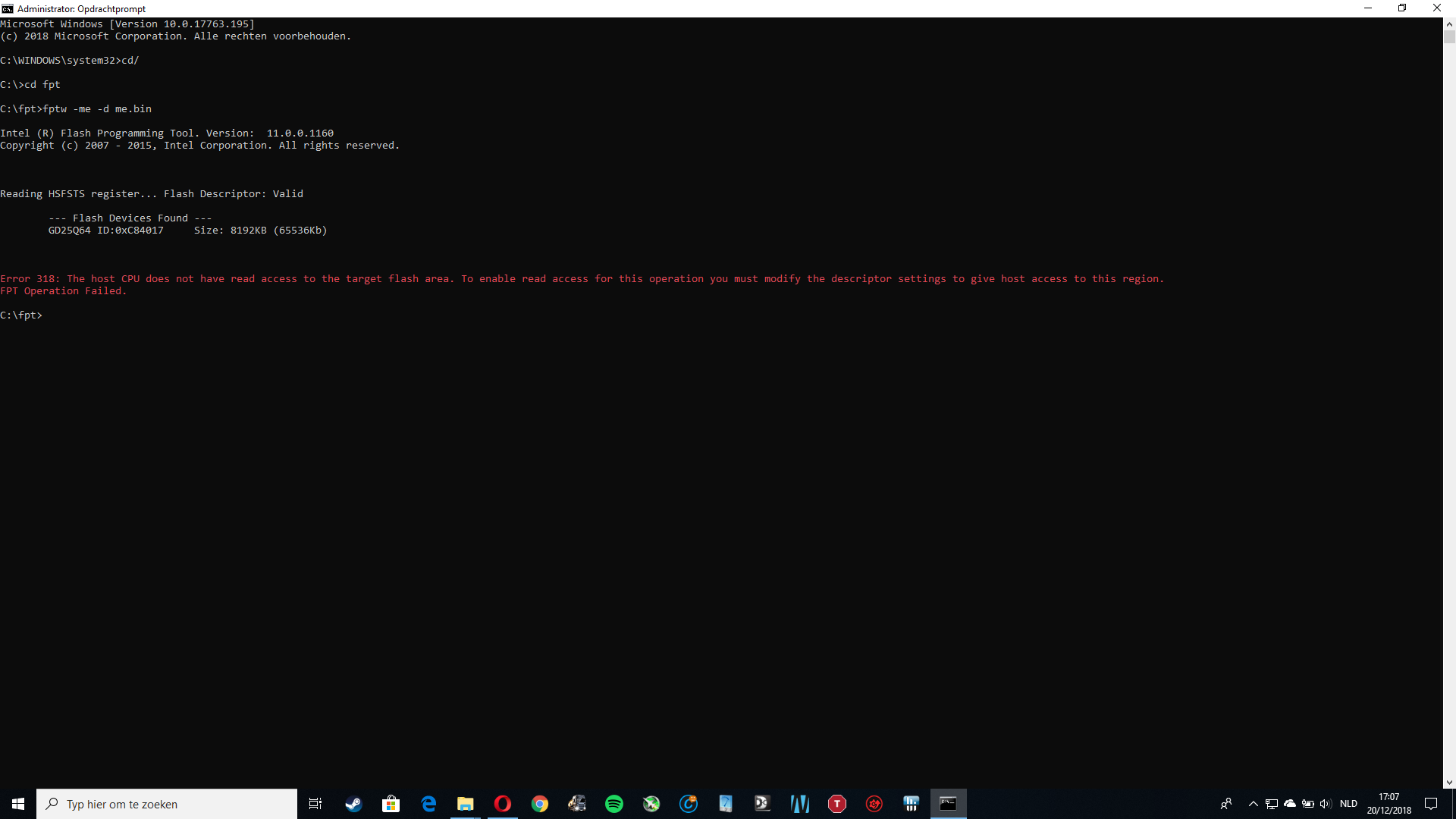
For some reason i could not dump the me region.
Tried with cmd.exe admin privileges, dumped with fptw -me -d me.bin Tried with fptw64 and fptw.exe and fptw64.exe. Picture included.
I am now testing the diffirent biosses you gave me.
Will post the results today.
Pictures are here.
Pictures.zip (182 KB)
Hi Stefan.
You may know me from NBR–I’m the guy who helped paloesco write the MSI unlock and EC RAM hacking stuff.
I looked in your bios and everything looks like it should work.
But the menus you unlocked don’t appear?
What happens if you set the options to SUPERVISOR instead of USER?
Also why isn’t the unlock 4 key combination working ? That is the correct combination. Pretty sure GT72VR did use this.
I know the Kaby Lake version did this. But you have Skylake. But the skylake GT73VR worked fine (6820HK).
Did you press F2 last? It has to be the last key pressed.
But your key combination does not work?
What happens if you try F1 instead of F2?
Try that first.
I also made a few changes to your file. See if this helps (even if the hotkey works).
*Edit @Lost_N_BIOS may have beaten me to this.
biosreg.zip (3.1 MB)
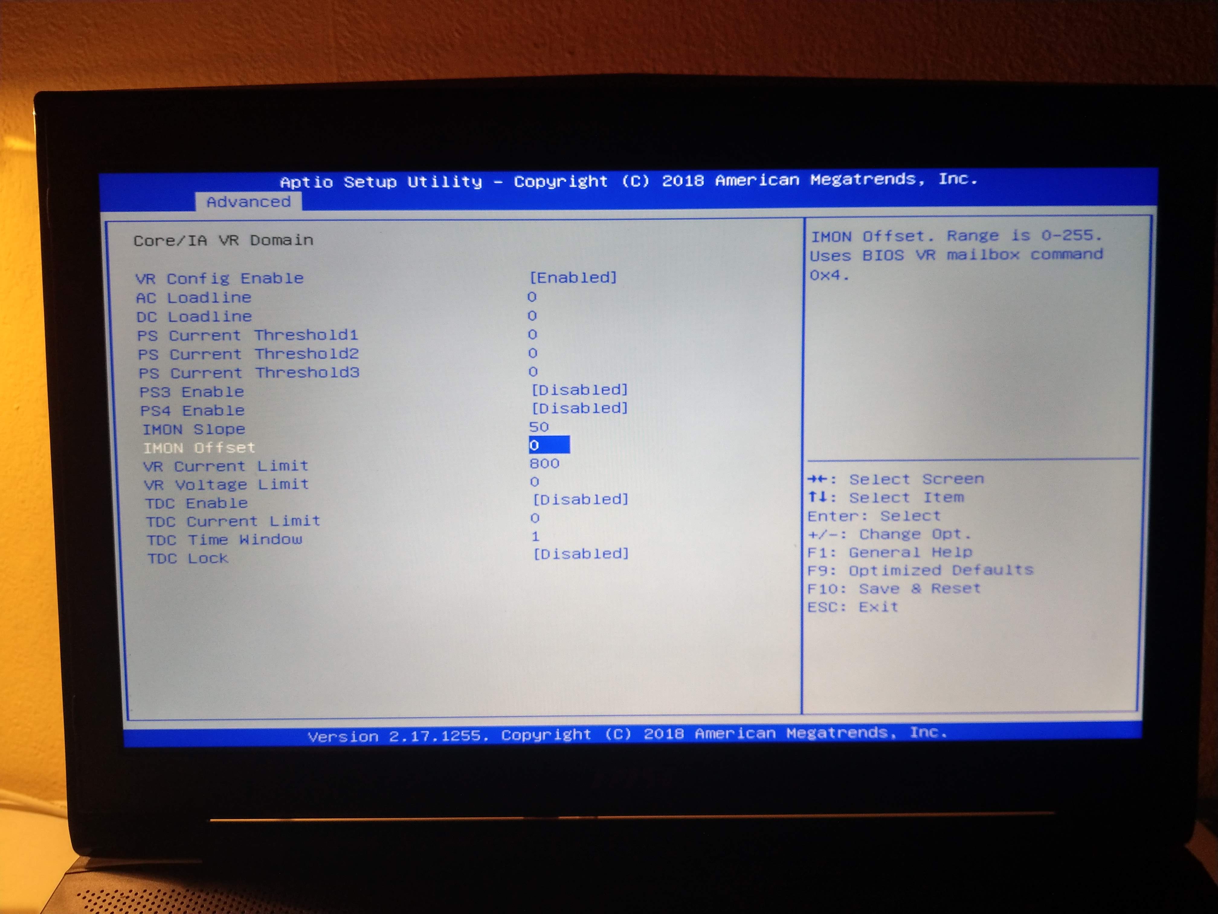
Hi, thanks for the info. the unlock key code works, unfortunately with the menus unlocked in admin mode i can’t bypass the 45watt limit while gaming. i changed pl1 and pl2 to 100000. and in core domain cpu vr settings. vr current limit to 800. so that my core icc max is at 200A.
but the cpu still throttles at 45watt. (power limit throtteling) I don’t have the options, power limit override
i have set all options on supervisor, i will attach a bios (all set to supervisor). i tried this a few weeks ago, didn’t work.
i will try your modified bios, thanks.
@Lost_N_BIOS , i have tested all your biosses, all 3 didn’t work. i flashed them in windows each time, and in dos with bootable usb drive. I didn’t forget to restore the optimized default settings and booted back in bios.
(while flashing it says pdr region does not exist, gbe region does not exist, shows up in a yellow collor. i looked it up, and they say that it just means that the flash doesn’t affect both regions.)
Thanks for helping, both of you!
bios.zip (3.09 MB)
You need to set IMON SLOPE to 50 in CPU VR Settings.
If that’s not enough, set IMON OFFSET to negative (prefix) 31999. In CPU VR Settings.
This will bypass that.
If you unlocked power limit settings that do not appear when you do the unlocked key combo(I tried that), those PL settings don’t seem to work right. If I recall, the non working ones were in “View/Configure turbo options”.
The working ones were in the “OC” section but this is on the GT73VR. I can’t test yours as I don’t have access to a GT72 at all.
Thanks, but i can’t set my offset to negative. and the range is set from 0 - 255. (picture included)
Maybe there is a method for this, so that i can put the correct number in it. But in amibcp there is also no prefix. I have seen this solution before on other forums
I assume that changing the imon slope to 50 doesn’t work without the offset set to negative prefix 31999.
i also enebled IMON support to see if something appeared. still the same.
I have no OC section unlocked.
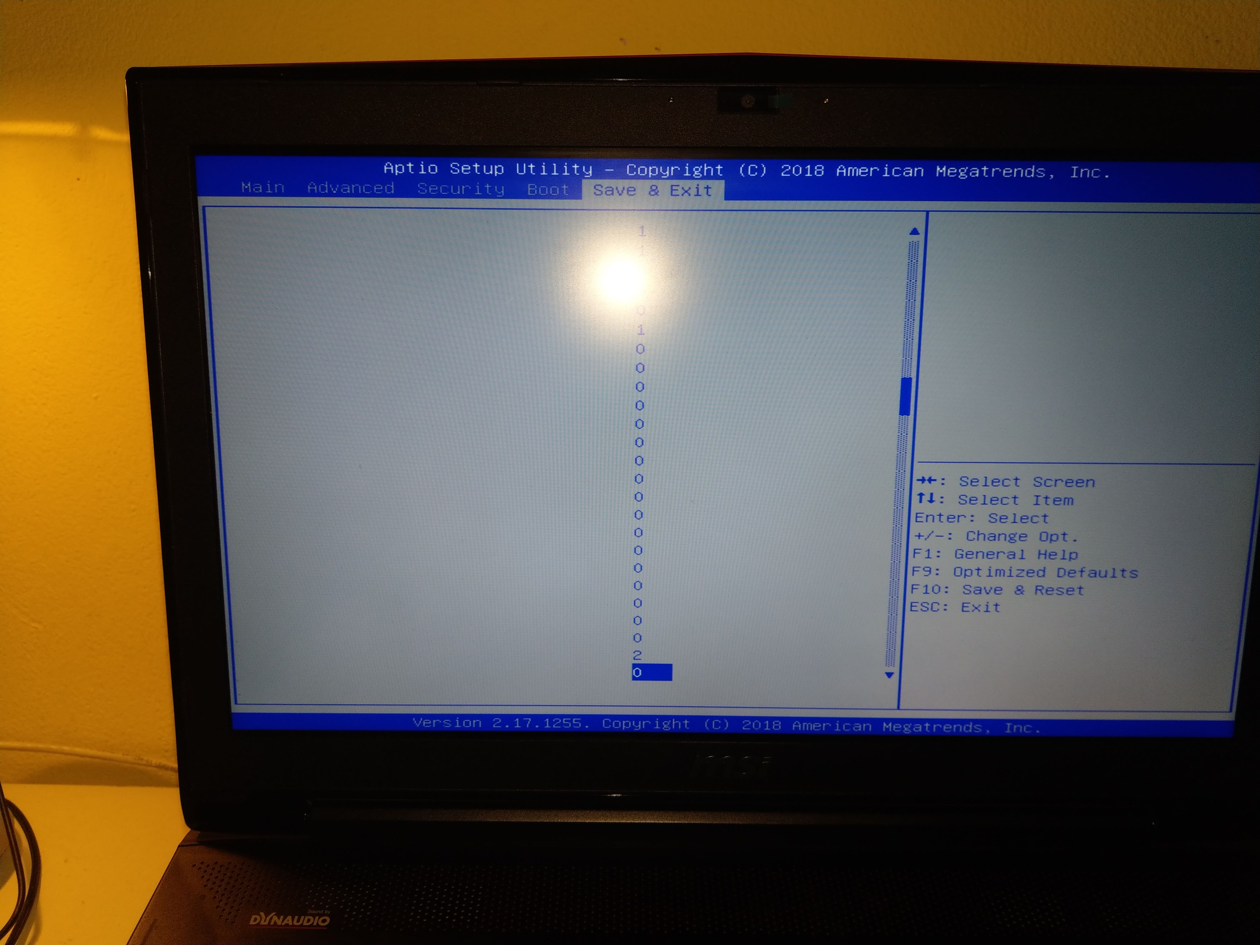
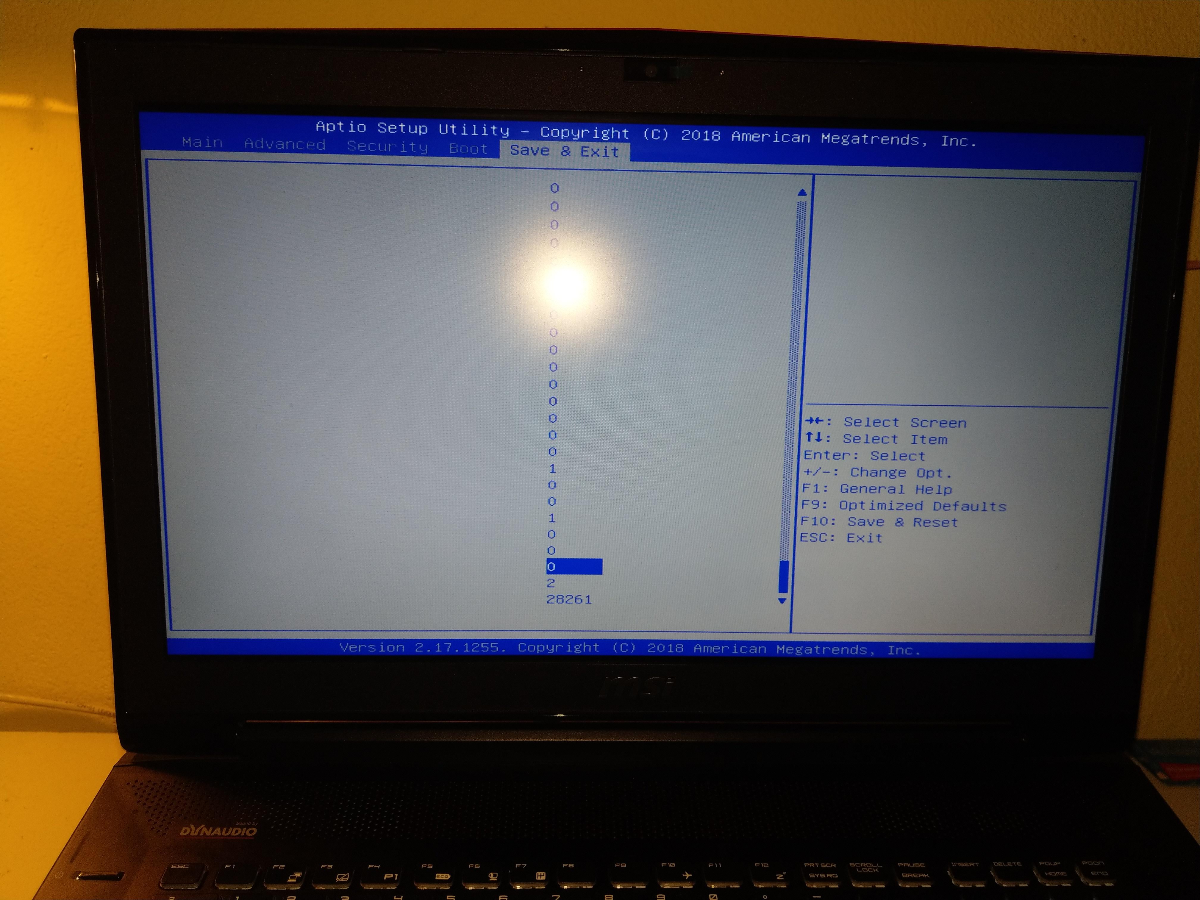
after i flashed your modified bios a lot of numbers appeared in save&exit (pictures included)
All I did was change those options from user (that you had) to "Supervisor"
I think some of them are bugged in supervisor.
You said that when you had it at USER, nothing worked.
So just go back and change "save and exit" back to "user".
I had mine in my own bios as supervisor because it does the same thing as the "key combo"–unlocks an extra option called "discard changes and restart", which is quite useful (power cycles the laptop and reboots).
If those numbers are distracting just re-edit the file i sent you and set the "save and exit" menu folder (forgot what it’s called) to "User"
Imon Slope does work. You can change it to 1. it should stop TDP throttling.
Imon offset is a fixed percentage of some sort. Imon slope is , 100=100%. 199=199%. But it stops scaling under 50% (50) on some systems. On some systems it can work as low as 10 (10%).
Try IMON SLOPE=10.
Also try an imon offset of 1.
It seems your imon offset is coded differently. I do not know if it allows negative values for TDP like newer bios (GT73VR, etc)
I set save and exit back to default
I do not know why you have no OC section. I did unlock it.
biosreg2.zip (3.1 MB)
@stefanr740 - Yes, PDR/GbE does not exist is normal, I will check it out the images. * I checked your images, BootGuard is not enabled, thanks for checking. And not being able to dump ME is normal too
Thanks for jumping in to offer help too @Falkentyne - which method do you use to unlock OC tab in this BIOS?
I did three methods in the files I sent him, but will have to check my folder for this to know which I tried. * Edit - I checked, I did IFR enable, AMIBCP Enable, and IFR+AMIBCP - all mainly root OC tab unlock only, except with all I also enabled first 1-2 settings (only) within as initial check test.
So asking to see if I’ve already used the correct one since he said all failed. I only enabled root of the OC folder, and a quick test, three ways, maybe one I did was correct but needed to further set/enable the rest inside for him before it would be visible.
I simply set the OC menu to supervisor in the parent menu.
This works in the Gt73VR bios to unlock even menus that won’t appear in the 4 key unlocked combination (e.g. menus which are not designed to be used with that hardware, like AMT configuration, Platform settings, etc).
The GT72VR was not designed to have an OC menu as far as I know, as these SKU’s were originally made for HQ series CPUs (6700HQ and 7700HQ). The 6820HK model is a very rare SKU, and I have never seen anyone get power limit overrides to work on it. I actually believe now this is caused by the Embedded controller, not the bios, if the EC doesn’t have a “power ID” for an unlocked CPU.
I saw someone’s EC dump and this SKU had a “20” value stored in EC RAM register E3 (viewable in RW Everything -->Embedded controller).
I actually changed the value in my EC on the GT73VR (default value is 90 for GTX 1070 in kaby lake GT73VR), from 90 to 20.
The bios seemed to recognize the change and allowed a power limit override of custom TDP (e.g. 200W) for only 28 seconds. Then power limit 1 flag came on. No PL2 flag ever came on. For example changing the EC register E3 to 30, for example, causes PL2 to get flagged instantly as soon as you exceed 45W.
This is unavoidable if there is no other unlocked SKU present in the EC itself.
@stefanr740 can try changing the value in EC RAM register E3 to a value of “10”, however if this value is not recognized for a 6820HK SKU, he will have instant 45W TDP throttle right away, and is better off changing it back to 20.
Imon slope = 10 should make the CPU report its using less power than 45W and should avoid problems. But again i do NOT have this laptop. I cannot test these things.
Imon slope =10 works wonders on the 8750H and 8850H and 7700HQ MSI laptops.
Thanks, would User work there too, or only Supervisor (07)? Thanks for all the additional info too, hopefully it will help him some!
@Lost_N_BIOS @Falkentyne
I think i have found the menu strings in the hx editor. (picture included)
the string: 01 01 00 00 01 01 01 00 00 00 (00), only found 1 identical result
can i maybe change the string to : 01 01 01 01 01 01 01 01 01 01 (01).
These are the related posts on other forums.
link1: https://github.com/the-darkvoid/XPS9530-…ocking-the-BIOS
link2: https://forums.mydigitallife.net/threads…r-unlock.54523/
Should i change the string, ore is it to dangerous.
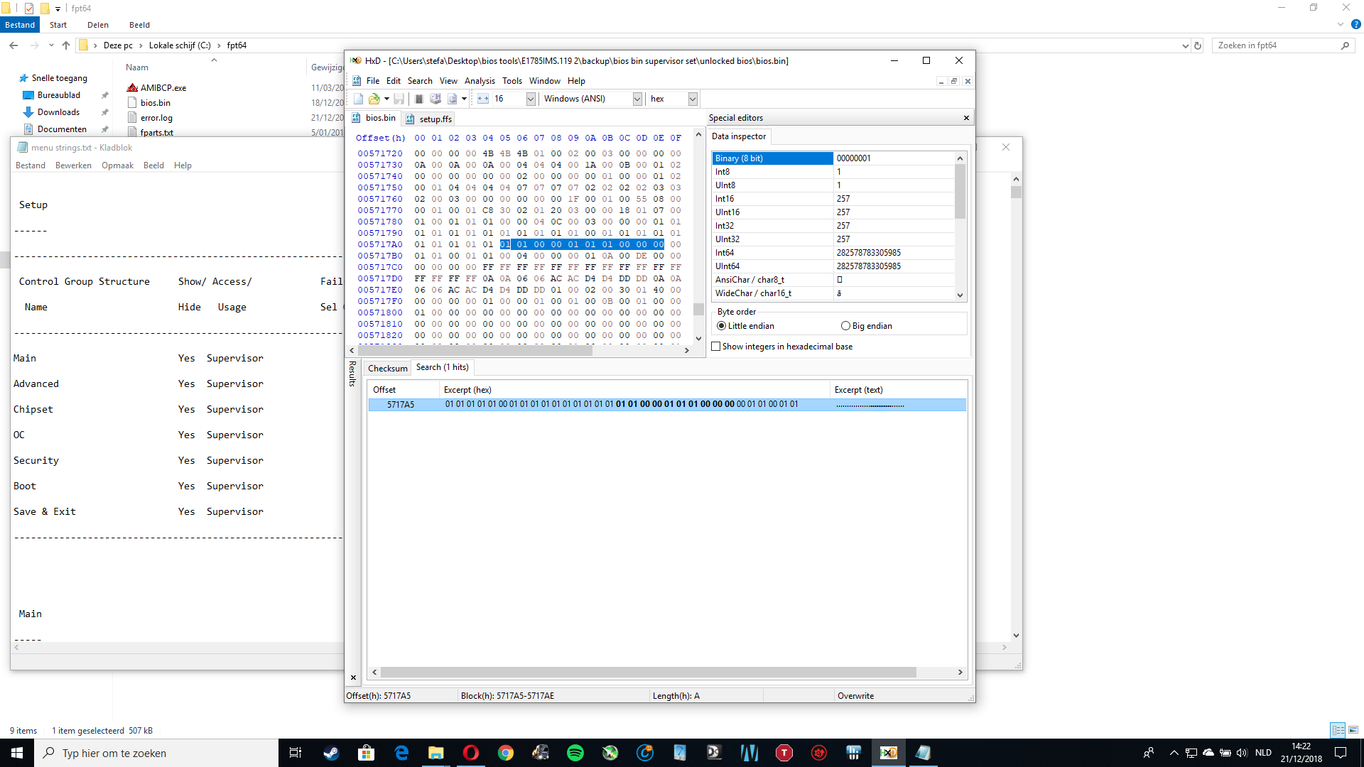
This is one of the things we all look at first usually, so I’ve checked about that method long ago. I find 28 results of the string you provided on straight BIOS search and zero in setup module
The one you are looking at @005717a0 is some settings enable/disable values inside a padding file that contains some NVRAM variables outside of NVRAM section in a RAW file at GUID 77D3DC50-D42B-4916-AC80-8F469035D150, scroll up a bit and you’ll see the NVRAM header info (Again this is outside NVRAM area too for anyone reading later)
You can check that in UEFITool Action, go to offset and then you’ll see the GUID where it’s located, if using UEFITool NE you can hex view and see same hex you have open. These string values always only inside setup module, some rare instances AMITSE, but it’s never any that seem like it in NVRAM which is all zeros and ones
That value you are using >> 01 01 00 01 01 01 01 00 00 00 doesn’t apply to your BIOS, if magic string method did work for your BIOS, then you would need to get your own string value based on what you see in actual BIOS vs what you see for root menus in AMIBCP, not what any guide gives as a standard example
"IF" just looking at your setup section vs AMIBCP, you would get the following for a magic string to try and find in your BIOS >> 01 01 00 00 00 00 00 01 01 01
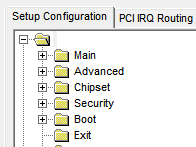
Normally, when setup contents are it’s own submenu this method does not apply like you are seeing in those guides. I’ve explained it a few ways here too, see the images at both links, for how a normal BIOS this works in looks in AMIBCP
[Request] How to Access Locked/Hidden BIOS Menu Settings (16)
Also here, shorter - [Request] How to Access Locked/Hidden BIOS Menu Settings (12)
When this works easily, the BIOS layout is like your BIOS setup submenu, only setup is not a submenu it’s the main menu and all the rest are submenu’s under setup. Hard to explain I suppose but see images above too for another example
This is the standard look of a BIOS layout in AMIBCP when that method does apply
And the string is usually trailed by ee 2e 20 71 53 5f d9 40 ab 3d 9e 0c 26 d9 66 57 (This is in your setup, but magic string is not)