I make this steps again, it could be helpful
step 2# insert clean ME v. 11.0.0.1191 (it shows this ME version in BIOS)
step 3# enable Reserved to yes (ME ver not showing in BIOS, listed as N/A)
I do that on 2 version of BIOS A91 and A40
But version A40 is saving BIOS settings with N/A ME and works like normal BIOS
There was only one change in config files
That is Reserved option in ME Kernel from No to Yes
ME N/A means corrupted ME, either bad flash or bad edit to the ME when saving/building BIOS.
Here is 4 test BIOS for you, be sure to reset ME State via greset or power drain for 1+ minute after each flash
https://nofile.io/f/mGyTACO6dfT/MSI+Z170-A+ME+Test.zip
These all have Rev 74 microcode, and 2 x 506E3 old codes removed, FIT table corrected, and then ME Yes/No for each version.
They left in 506E3 Rev FF, in all BIOS, along with newer version too in each of 506E3. I removed both, put in Rev 74 only, fixed FIT table after that.
Maybe they leave in FF version to disable something, no need for that when they put in new revision 506E3 both times, but still leave that older one too (It’s not ES ucode, so no reason to leave other than bad intentions 
 )
)
Intel Management N/A in BIOS after fpt -greset and CMOS battery out on 2 reserved yes bioses
I have on this BIOS message on boot about invalid ME
With reserved no not booted Xeon
When I changed CPU to Pentium G4400 and go to BIOS the version of ME is 11.0.0.1191 on 2 BIOS with reserved no
I found BIOS which save settings and no showing any errors with ME N/A on boot it is A4 version
Is invalid Intel ME reduce performance of computer and system?
I will try flashing next day because I ordered SOP8 clip, maybe it help something
That is strange, maybe you are right and MSI did something on this board BIOS, or forgot to do something, that causes that to fail?
But, to be honest, I am not sure what/how ME reserved should appear in BIOS, maybe N/A is correct. Does Xeon work or not on those BIOS, any of the four I sent?
ME reserved might only be needed if you want to attempt overclocking (Bclk), test Xeon on the reserved NO too
All my or your bioses with Reserved NO runs xeon with ME N/A in BIOS.
All bioses patched with me_cleaner with option -s runs Xeon but ME is N/A.
I’ll made bios A40 with Reserved NO and this old version is not checking ME state.
I figured the this BIOS works with xeon without BIOS reset, any messages and settings are saved ![]()
BIOS settings are reseted after save on BIOS maybe higher than A40.
I made A50 BIOS probably without option Intermediate Files and motherboard is now bricked 
I tried to insert Pendrive formatted to FAT32 with file named AMIBOOT.ROM, and I hit Ctrl + Home, the USB keyboard is working but PC shutdown about 2s (it’s on Pentium G4400).
I’m waiting for SO8 clip.
Is it possible to run recovery flash on AMI bios and how name files?
I think MSI have specific recovery options and functions, look around on their forum for recovery and you will find the method and tools.
So you had it running with no ME in BIOS, who cares about that, you want Xeon running with mod BIOS, you got that, why more changes needed other than that I am confused now?
I thought all this due to you couldn’t run Xeon properly
Obviously the CSME is reported as N/A when you set the Reserved bit or when running me_cleaner. Do you know what these do? The Reserved bit sets HAP (High Assurance Platform, NSA) which officially disables the CSE at an early stage. The utility me_cleaner corrupts the CSME firmware so that the CSE falls into Recovery, for those who are afraid of it. Since the CSE cannot initialize, its firmware is reported as N/A. So obviously what you see makes sense.
Xeon works now without BIOS reset.
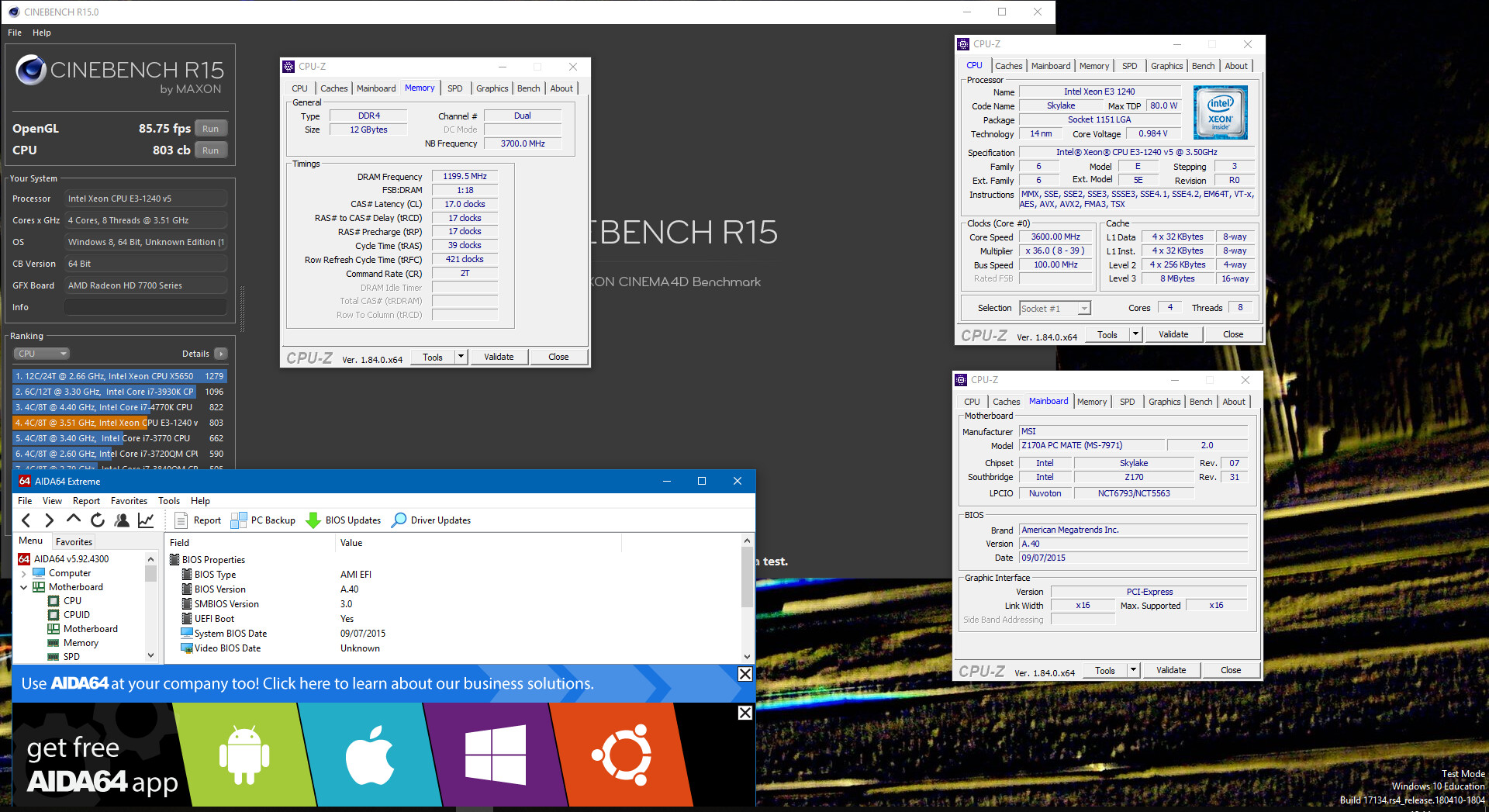
I’ll check perfomance with G4400 with Intel ME enabled/disabled and Xeon ME disabled.
Only way to recovery is CH341A when SO8 clip arrive to me.
You can’t boot to CD or DOS?
Yes,
Board run only for 3s and lights up usb keyboard for 1-2s.
I made FAT32 8GB pen drive with AMIBOOT.ROM and all 6 other names suggested from MSI site and the board turns off.
Well boot for 3s is not long enough for it to start doing anything, that’s bad  Hope you’re programmer arrives soon
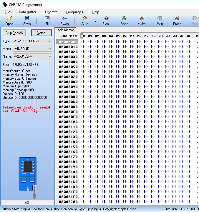
I have programmer and programmer shows $FF, $FF, $FF, $FF when connected to SO8 clip.
I have Winbond 25Q128FV BIOS chip.
It’s 3.3V chip.
Do you have any forum links for flashing via CH341A?
Then it’s not connected properly. Please show me images of your programmer, how you have the cable/PCB connected to the programmer, and how you have it connected to the board.
There is thread here, but no guide really. I tried to help another user here, and described from his images how he needed to make corrections, maybe that can help you by looking at his images and then my corrections I tell him to make.
Page 1-2 - Problem: DX79TO not booting properly
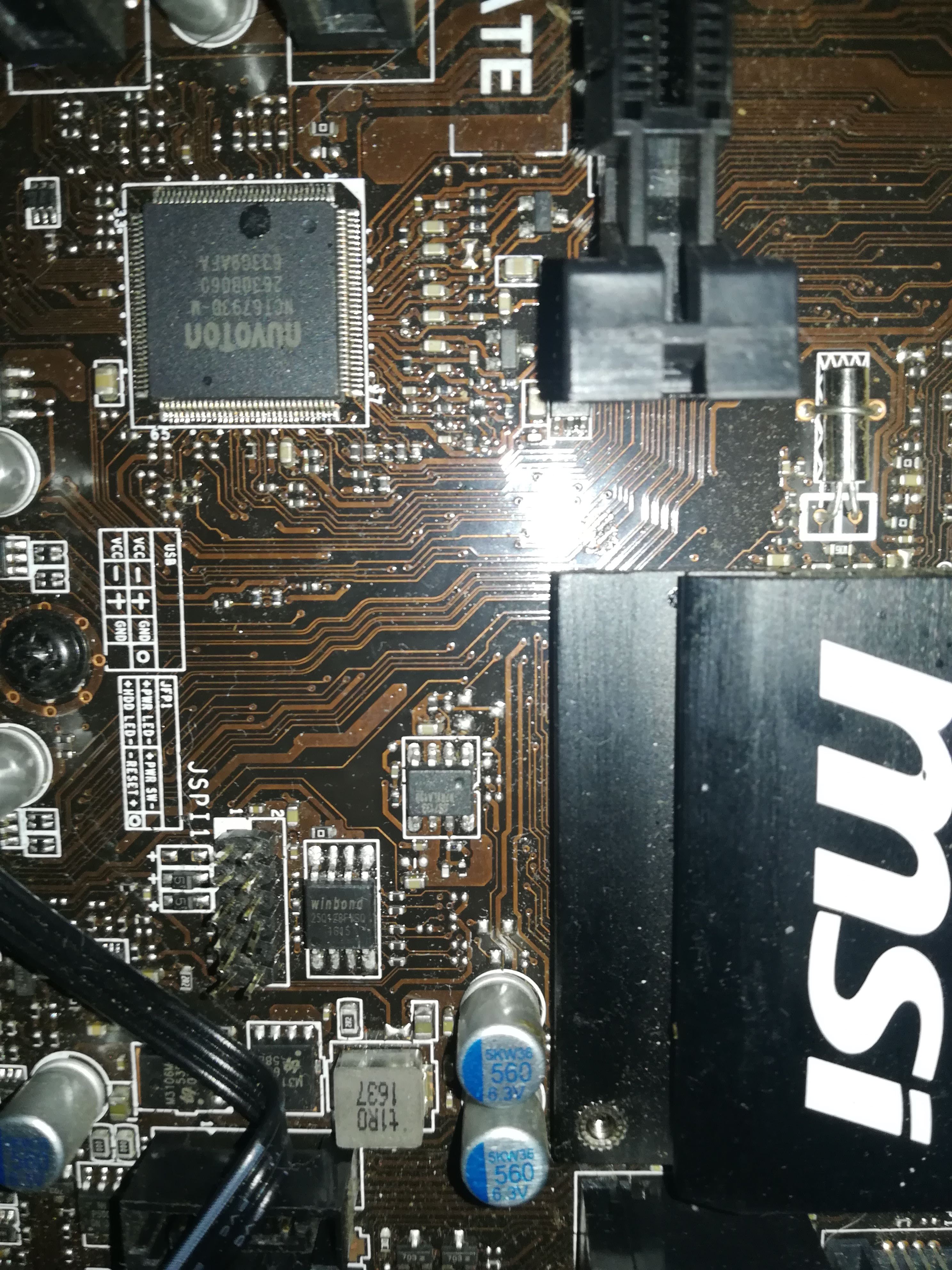
Basically, red wire must go to pin one location in programmer and pin 1 location on BIOS chip on board. Make sure you are looking at socket in programmer correctly based on it’s image and you use the “25” slot
Pin #1 on programmer socket is on the same side as lever, in the middle of the socket due to “25” socket is inner most socket nearest USB end of programmer.
Pin #1 on motherboard BIOS has either a white triangle or #1 pointing to pin 1, if not look at BIOS chip itself and find little dot/circle by one corner that will be pin 1
If all is correct, then connection is not good at the chip side or programmer side.
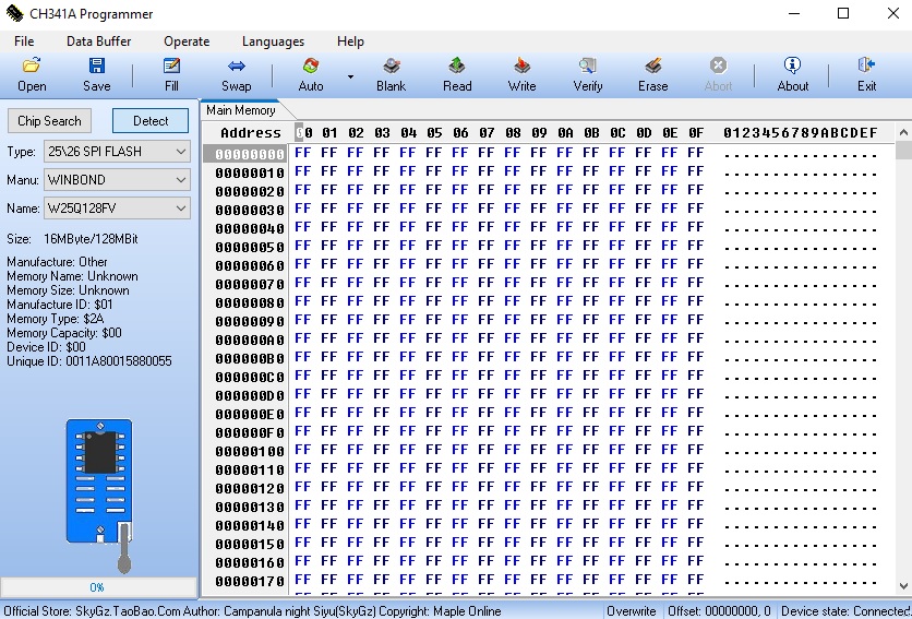
I think the programmer not working properly…
The result of detect button is randomly generate variables (other than previous).
In attachment example readings from ch341a v 1.29.
Is it possible to flash BIOS via LPT port?
I have SEGGER J-Link-ARM with JTAG interface.
https://www.segger.com/products/debug-pr…ls/j-flash-spi/
I tried to flash but original old v8 is incompatible with spi flash.
Random variables is what you want (FF for chip ID values is not, that means no read/no connection etc). Sometimes you can’t pick exact match to chip ID, only close, like instead of W25Q128FV or W25Q128BV you have to pick W25Q128, or if BF try FV or FV try BV etc.
Sometimes you need different software version Try 1.31/1.4 from this package - https://www.sendspace.com/file/gtcmvd
I have no clue about seggar JTAG LPT etc.
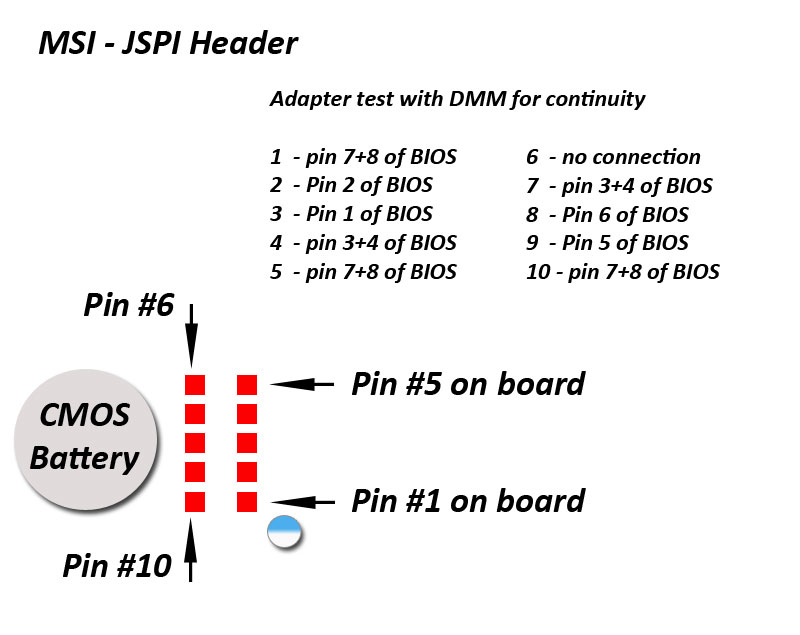
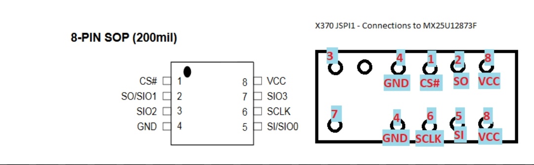
BUT, I have this I made from MSI’s JSP1 header, this header you connect BIOS to on spare flash and system boots to this BIOS, then you unplug while in BIOS or DOS and reflash main BIOS
See also, this thread, another user posted his reverse pinout and mod flash method
Flashing BIOS chip (MX25L3205D) with CH341A progammer - can’t detect chip
Is that your exact chip? W25Q128FV If yes, I think maybe I have some (W25Q128FVSG), I will put in my programmer and see which version can detect and read/write properly, and what it’s values are.
Still no images of programmer, board, cables connected and how they’re connected etc. Lets check this to be sure.
Yes, please send images of all that, something is not connected correctly on your end.
I checked exact chip, exact software version, and exact programmer you have (Black one correct) And see, here is proper detection
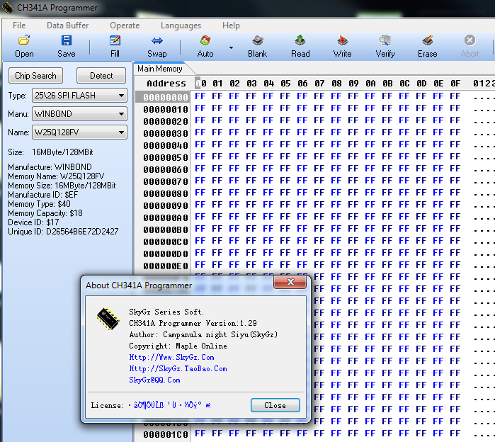
Yes this BIOS chip is W25Q128FVSQ
This is black edition.
But I’ll tried connect to another W25Q64BV the programmer won’t detect properly chip.
I’ll cleaned bios chip and programmer with ethanol, with no luck.
In attachment pinouts of SPI port (I’ll tried to connect by pins but the results are exact).
I think the programmer is too old (I bought it many years ago) and something don’t connect to chip.
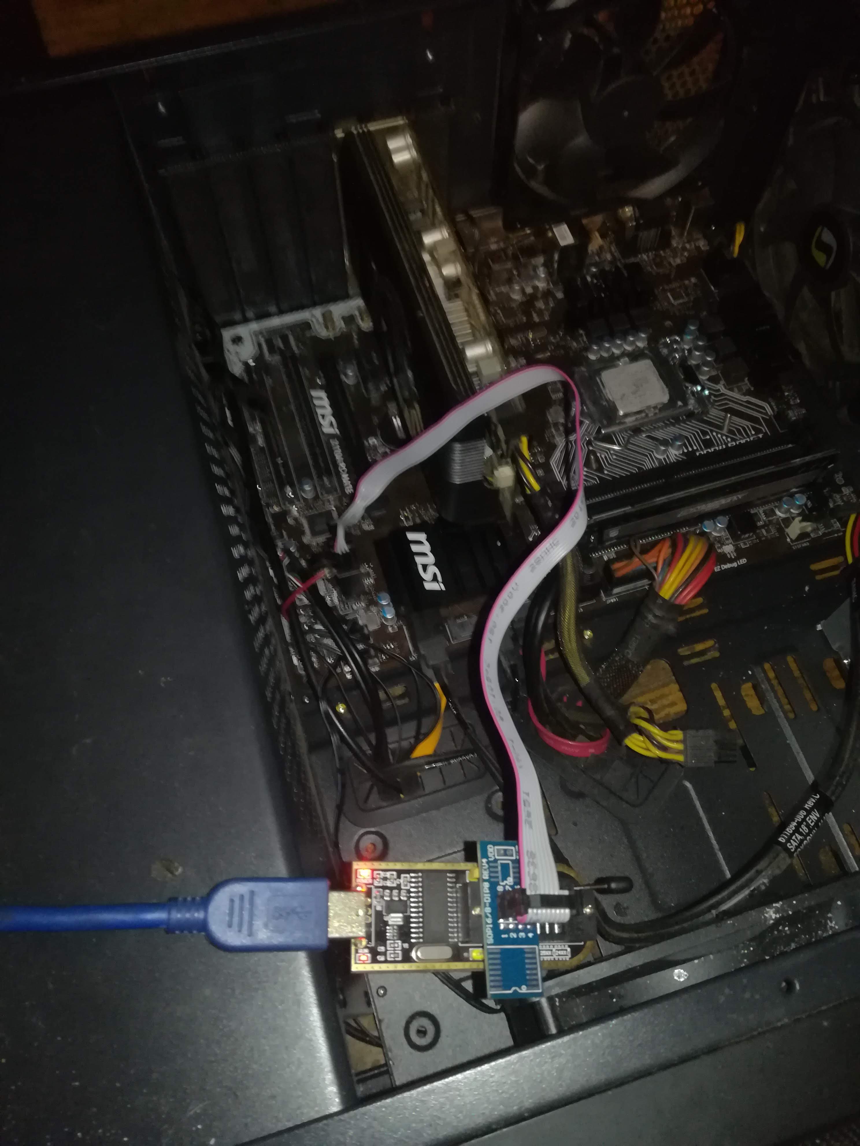
Second image, with cable to board/BIOS is not clear enough at motherboard location to see what is going on there, please take again, it’s blurry but looks like you have it wrong too.
For now, I can see cables going into programmer are wrong. Red cable needs to go on other side, pin 1 is on lever side, turn that end of connection 180 degrees so pin1/red wire is on lever side/middle.
I can’t see the board, but red wire from programmer needs to go to pin 1 on BIOS, which is bottom left corner in the orientation of the image1 shown here.
What is that big red wire in image 2?? Nothing else should be connected to the programmer cable
I flashed the BIOS, you have right the connection was incorrect.
It works but the 1 thing is weird.
A60 or A6T (modded to non k oc) shows error message about ME, and all newer with mod.
The A50 with mod won’t booting Pentium or Xeon after set Reserved to NO.
I think the A50 version is first version with ME checking and it won’t boot because it is messed…
The A40 version works fine without any errors.
When the motherboard AC has power failure (lost power from PSU), it’s not starting and when I clear BIOS (ver A40) it boots normally…
I connected the reset button from old case to bios reset pins and it is outside of the computer case ![]()
You asked me about image with pinout of new MSI JSPI1 port, this is scheme how to connect to new MSI motherboards. I checked the connection and it is needed to connect only pins with description on this image.
I don’t know anything about A60 or A6T etc? I can only comment on BIOS I modified. I’m glad you got your board recovered and running now!!
So you test BIOS I sent again yet, with ME reserved NO?
I have checked and it run only Pentium.
I want to check if there is a performance difference on Pentium with ME reserved NO/Yes.