@ all users, who want to manually optimize the UEFI BIOS of their manboard/system:
Since the company American Megatrends Inc. (AMI) doesn’t allow to offer their AMI Aptio UEFI MMTools for the public, you may have to use another tool, if you want to manually modify an AMI UEFI BIOS according to your wishes.
My favorite UEFI BIOS modding tool for these specific tasks is the normal "UEFITool" (don’t use the _NE variant for this purpose). Both tools have been developed and are still kept up-to-date by our Forum member CodeRush.
At first view the usage of the UEFITool may not be as comfortable and easy to understand as the usage of the related AMI Aptio IV or Aptio V UEFI MMTool, but these are the benefits the users of the UEFITool will get:
The UEFITool
1. can modify all "pure" (=extracted) AMI UEFI BIOS files (no matter whether its structure is Aptio IV or Aptio V),
2. works absolutely precise and very safe (e.g. it automaticly corrects the checksum of an FFS file while inserting/updating it) and
3. is free and can be used by everyone (since it is an "Open Source" project, there are no restrictions).
That is why I recommend to use the UEFITool, if you want
a) to insert a previously not present EFI module into a specific mainboard UEFI BIOS or
b) to manually replace an already existing EFI module by another version or variant.
Since the UEFITool "maker" CodeRush himself hasn’t yet published detailed instructions regarding the usage of all specific UEFITool options, I decided to offer here a short guide just about how to insert/replace the most important EFI modules into an AMI UEFI BIOS.
Note: the UEFITool can accomplish similar tasks with LEGACY mode Option ROM modules as well, but this is more complicated and not the topic of this guide.
Here is it:
Guide about how to
extract/insert/replace an EFI BIOS module
by using the UEFITool
(last updated: 12/30/2019)
Introduction: What are "EFI BIOS modules", .ffs files and .efi files?
- EFI BIOS modules (= "DXE Drivers") are managing specific devices while booting in UEFI mode. They are located within a special "DXE Driver Volume Image" of the BIOS Region, which is part of the complete BIOS.
- If you want to insert, replace or extract an entire "DXE Driver", you need resp. get an .ffs file. This file with the FFS extension contains the complete code of the related EFI module (incl. GUID header and infos about dependencies, size, version etc.) in compressed or uncompressed form.
- The code, which is responsable for the function of the DXE Driver is located within the Core of the EFI module named "PE32 Image body". If you want to extract or replace just this functionally essential part of the EFI Module, you need resp. get an uncompressed .efi file. Since these files with the EFI extension do neither contain a GUID header nor infos about dependencies, size etc., they are a little bit smaller sized than the uncompressed .ffs files.
This is what you need, before you start:
- The latest stable Windows version of the "UEFITool" (currently newest: v0.28.0).
You can download it either from >here (developer’s link)< or from >here (OneDrive link)<. - The "pure" BIOS file, which you want to use as source (for the extraction of an EFI module) or as target (for the insertion or the update of an EFI module)
- The desired uncompressed *.ffs file (has to contain a GUID header), if you want to insert a previously not present EFI module into the BIOS.
- The desired uncompressed "pure" *.efi file (without GUID header).
- optional: An Hex Editor like the tool HxD (only needed, if you want to verify the code or the version of the EFI module).
The latest multilanguage variant of this tool can be downloaded here:
Note: All offered RAR archives are compressed by using WinRAR v5.xx and should be unzipped with a similar tool (which supports the new compression method).
General info about the usage of the UEFITool (valid for all tasks):
- Only previously unzipped "pure" AMI UEFI BIOSes can be opened and modified by the UEFITool. The BIOS file name and its suffix (except *.exe) doesn’t matter.
Before you start the UEFITool, you should make sure, that the related BIOS file complies with these requirements. - After having done a double-click onto the UEFITool.exe file, you will see its GUI.
Tips:- It is generally a good idea to maximize the UEFITool GUI window from scratch to see later on the complete content of the opened BIOS file.
- When you are opening the UEFITool for the first time, it has default window layout, which doesn’t show the Text column, makes GUIDs too short etc. To combat it effectively, you can select the root element, press numpad * to open the whole tree at once and double-click onto the borders between column headers to resize them to content. This will make the tree view look much better and next time it will look the same way because column widths and window position are stored in system-specific settings storage.
- To open a certain BIOS file, hit onto "File" from the UEFITool Toolbar and choose the option "Open image file…". Then navigate to the folder, where the related BIOS file is located.
- BIOS files with a "standard" suffix (like *.rom, *.bin, .cap etc.), will be found and listed automaticly by the UEFITool. If the BIOS file has a non-standard suffix, you have to change the "BIOS image files" option at the right-hand side of the bottom to "All files ()".
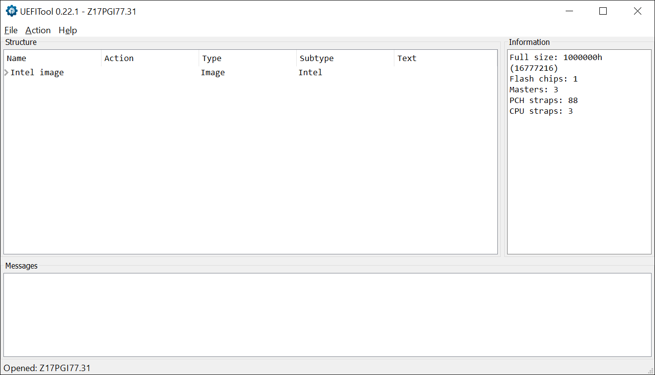
- After having successfully opened an AMI UEFI BIOS, the UEFITool GUI will look like this picture:
A. Extraction of a "pure" EFI module Core as *.efi file
This is the way to do it:
- Open the source BIOS file with the UEFITool.
- Expand the "BIOS Region" and search for the DXE Volume, where the files of the Subtype "DXE driver" are located (Tip: The UEFITool has a good "Search" option. Search for "DXE").
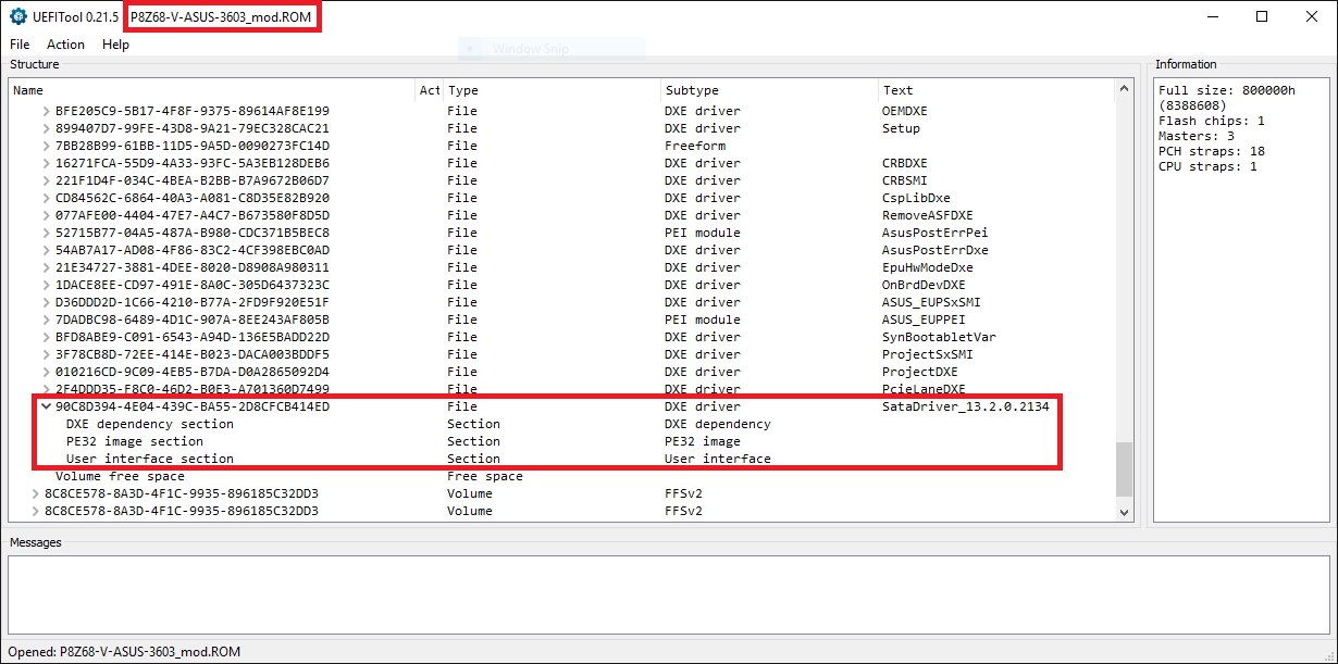
- Expand the listed DXE driver module, whose PE32 image body you want to extract.
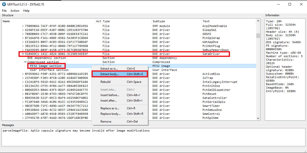
- Right-click onto the "PE32 Image Section" of the related DXE driver and choose the option "Extract body...".
Here is the picture I got at this point of the processing (it is just an example):
- Navigate to a folder, where the extracted file shall be stored, give the file a meaningful name and save it with the suffix *.efi (e.g. as "RaidDriver_v13102126.efi").
- Now you can close the UEFITool.
[Optional] Verification:
- Open the file by using the tool HxD.
- Look into the right ( text code) part of the tool's GUI and search for readable useful informations.
Notes: The text code of all uncompressed *.efi files should begin with the letters "MZ" (hex code: 4D 5A). All uncompressed EFI modules contain infos about their function, some of them even their version number.
B. Insertion of a natively absent complete EFI module
Here is a short guide:
- Open the source BIOS file with the UEFITool.
- Expand the "BIOS Region" and search for the DXE Volume, where the files of the Subtype "DXE driver" are located (Tip: The UEFITool has a good "Search" option. Search for "DXE").
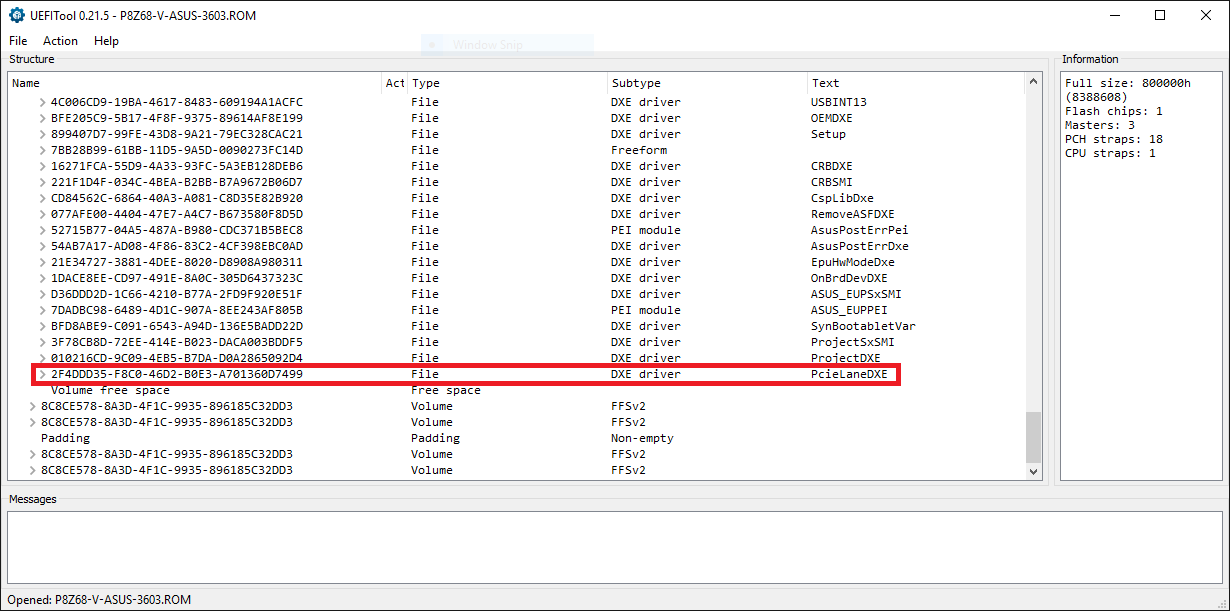
Important note: Some AMI Aptio IV BIOSes have more than 1 DXE driver Volume. The correct target DXE Driver Volume is the one, where the module named "CSMCORE" is located. - Expand the DXE Volume and scroll down to the undermost module, which is listed as "DXE driver".
Here is the related picture (in this example it is the DXE File named "PcieLaneDXE", but within your BIOS it can have any other name):
- Right-click onto the GUID of the undermost listed "DXE driver", choose the option "Insert after...", navigate to the EFI module file you want to insert (must have the suffix *.ffs!), and double-click onto it.
After having done that, you will see a picture like this:
Note: If there should not be enough space within the DXE Volume for the insertion of the additional EFI module, you will get the message "File size exceeds the Volume size". In this case it may be necessary to remove another "DXE driver" to get the required free space within the DXE Volume. >Here< is a tip given by our BIOS Guru CodeRush about which "DXE drivers" can be safely removed (unless the user wants to use the "Wake-on-LAN" feature). - Don’t forget to save the modded BIOS as final step of the modding procedure. You can start it either by clicking onto "File" > "Save image file…" or by hitting CTRL+S. Then you can navigate to the folder, which has been designed for the modded BIOS (e.g. D:\Mod BIOS), choose a meaningful BIOS file name with an appropriate suffix (you can use any suffix, if you choose the "All files" option) and click onto the "Save" button.
[Optional] Verification:
- Immediately after you have saved the modded BIOS the UEFITool will offer you the option to open the reconstructed file. Click onto "Yes".
- Expand the content of the "BIOS region" and then the content of the DXE Volume (see above).
- Scroll down and go to the undermost listed "DXE driver". It should be your just inserted EFI module.
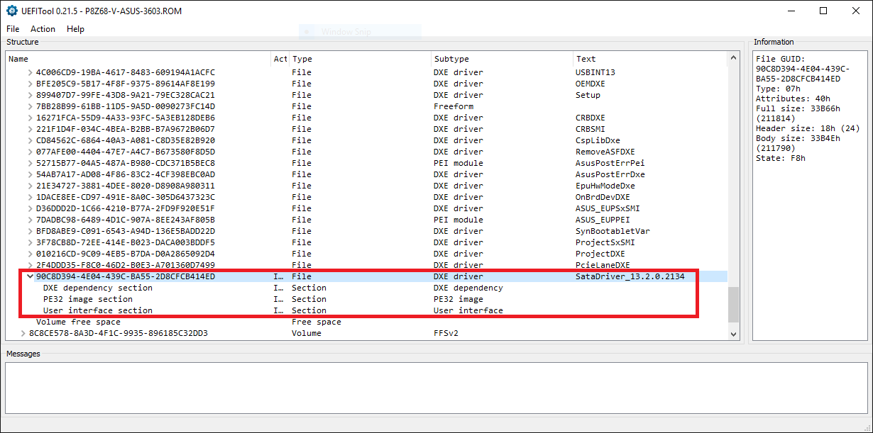
- Expand the sub-sections of the related EFI module by clicking onto the downside arrows.
What you will see, is similar to this picture:
- If everything looks fine, you can be sure, that the related module has been properly inserted into the correct GUID section, and you can close the UEFITool.
C. Replacement/Update of a "pure" EFI module Core
Here is a short guide:
- Open the source BIOS file with the UEFITool.
- Expand the "BIOS Region" and search for the DXE Volume, where the files of the Subtype "DXE driver" are located (Tip: Use the UEFITool "Search" option and enter "DXE").
- Expand the DXE Volume and search for the DXE driver you want to replace. Scroll down until you find the DXE driver, which is listed with the matching text within the right "Text" column.
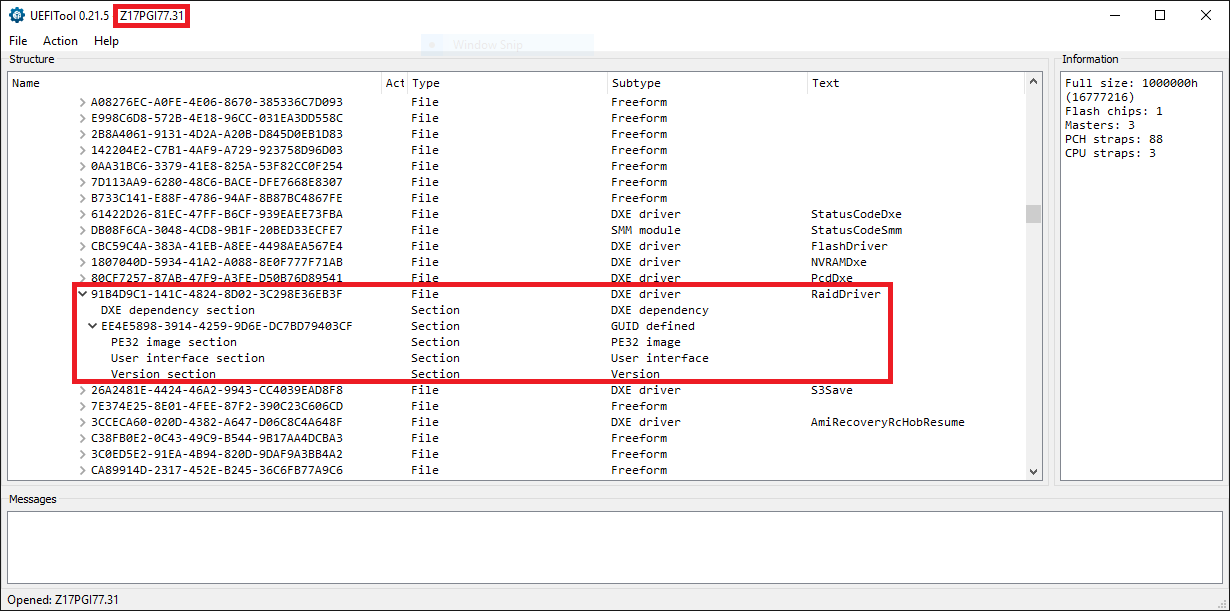
- Expand the target DXE driver.
Here is the related picture (in this example it is the DXE driver named "RaidDriver"):
- Right-click onto the "PE32 Image Section" of the related DXE driver and choose the option "Replace body...".
- Navigate to the folder, where you have stored the desired "pure" EFI module (without GUID header), which you want to get inserted instead of the currently inserted one. The desired EFI file must have the suffix *.efi!
- Double-click onto the desired *.efi file.
After having done that, you will see a picture like this:
Note: If there should not be enough space within the DXE Volume for the insertion of the additional module, you will get the message "File size exceeds the Volume size". In Chapter B you will find a solution for this problem. - Don’t forget to save the modded BIOS as final step of the modding procedure. You can start it either by clicking onto "File" > "Save image file…" or by hitting CTRL+S. Then you can navigate to the folder, which has been designed for the modded BIOS (e.g. D:\Mod BIOS), choose a meaningful BIOS file name with an appropriate suffix (you can use any suffix, if you choose the "All files" option) and click onto the "Save" button.
[Optional] Verification:
- Immediately after you have saved the modded BIOS the UEFITool will offer you the option to open the reconstructed file. Click onto "Yes".
- Expand the content of the "BIOS region" and then the content of the DXE Volume (see above).
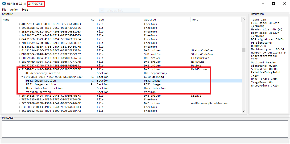
- Scroll down and go to the specific "DXE driver" you just have replaced by another version/variant.
- Expand the sub-sections of the related EFI module.
- Right-click onto the "PE32 Image Section" of the related DXE driver and choose the option "Extract body…".
- Navigate to a folder, where the extracted file shall be stored, give the file a meaningful name and save it with the suffix *.efi (e.g. as "RaidDriver_new.efi").
- Now you can close the UEFITool.
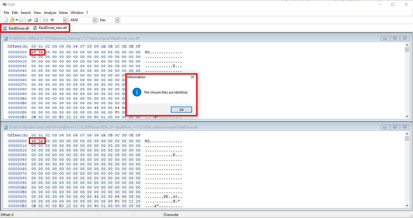
- Run HxD and let it open simultaneously
a) the just extracted new *.efi file and
b) the source *.efi file you had inserted at step 6 of the above guide. - Choose the HxD menu option "Analysis" > "File-compare" > "Compare". After having checked, that HxD shows the correct paths to the 2 *.efi files, which you want to be compared, click onto "Ok".
- If HxD gives you the pop-up message, that both files are identical, everything worked fine and you can close HxD.
Here is the related picture:
Disclaimer:
The BIOS modification itself is not risky at all, but flashing a modded BIOS may end with an unbootable system or even with a bricked mainboard/PC.
Neither the maker of the UEFITool nor the author of this guide will overtake any responsability, if anything should go wrong.
Everything that's done with the UEFITool needs to be done by people, who
a) understand, what they are doing, and
b) know, that they alone are responsable for their action.
Good luck!
Dieter (alias Fernando)