Hey guys,
I recently updated my BIOS and this has sent my desktop pc into a reboot loop. Now I’m wondering if I could fixed the BIOS externally with this CH341A + Clipper kit:
CH314A Kit
The Gigabyte Z390 Designare features two BIOS chips of the following brand:
MXIC MX
25L12872F
M2I-10G
58912100
Here’s a picture of the two chips: BIOS CHIPS
As I do not have any soldering tools, and the two BIOS chips are soldered to the motherboard, I’m asking myself if it’s feasible to update the bios directly on the motherboard (without desoldering the chips) with the kit above? Would I need extra power sources? Do I need to drain the mobo of residual charges before I start this process or can I just unplug the PC and start with the CH341A process?
@Lumberjack - Designare board without dual/single and Main/Backup BIOS switches (that’s slacking off)? Yes, you only need the programmer and the SOIC8 test clip cable, do you have the cable now?
If yes, make a backup of your MAIN BIOS, so you can put back in LAN MAC ID into new BIOS before you program it in, and possibly UUID, Serial (but gigabyte doesn’t always use those)
Yes, it is as easy as you mentioned, no power connected to the board.
Connect the cable properly to both programmer and main BIOS, and then before you write anything make sure you get a verified backup that’s valid.
Valid meaning it open in hex and make sure it’s not all 00’s or FF’s, and that it opens and looks similar to stock BIOS in BIOS tools such as UEFITool, AMIBCP etc.
If you are unsure, before you write anything upload your backup for someone to check, and to reinsert your LAN MAC ID and if UUID.Serial etc back into a BIOS for you to program.
Here’s two guides on using CH341A
[Guide] Using CH341A-based programmer to flash SPI EEPROM
And here’s setting up, with lots of images
https://www.bios-mods.com/forum/Thread-G…341A-programmer
[Guide] Using CH341A-based programmer to flash SPI EEPROM
Did you try the switch BIOS hotkeys (Or really, copy backup to main/main to backup)? This is done at startup via Control + F10
This is done when you’d normally press DEL to get into BIOS, spam CTRL+F10 a few times, if you get boot menu (F10) reboot and keep trying, best done with wired KB and PS/2 one if this board has PS/2
Thanks for the fast reply! Much appreciated!
No, I don’t have the kit yet, as I needed an expert opinion on this matter before placing the order. I’ll probably receive the kit next week due to new year festivities…
And yes, the Designare does come with DualBios, but everything’s automatic, i.e. no physical switches between the backup and main bios. What’s more, the backup bios does fire up, but it somehow still isn’t able to prevent these reboot loops. I’m not sure how such a seemingly harmelss procedure can lead to so much sorrow and destruction. The board is almost brand new, so I might get away with a DOA claim if all else fails.
I haven’t tried the CTRL + F10 method at the Bios screen - will try it later! Just to avoid misunderstandings: does CTRL+F10 flash the main bios with the backup bios or does it just force the pc to boot with the backup bios?
I do have the original backup bios on my usb stick - so I’ll be able to fil in the lan mac id, uuid etc.
What’s really strange in my case is that after a 12h+ wait with the PSU switch off and the power cable still plugged in, the Bios at least lets windows 10 start normally. If I reboot windows, it still functions properly, but if I choose to shut it down and then turn it back on manually, it gets stuck in the reboot loop again. I’m not sure what’s happening during that period that lets the mobo start normally. I tried the disconnect PSU from power and press case power on button for 60 seconds trick, but it doesn’t lead to the same result as the 12h wait.
I’ll be able to reach the bios normally in about 10h, so I will get another shot at a bios update. This time, I’ll choose the initial backup bios, but I’m not sure if an already corrupted main bios chip will really permit a correct bios flash.
And a general CH341A question: Are bios firmware updates with the CH341A safer/more reliable than q-flash and other convential methods? Is it possible to damage the bios chips with that method?
If you need help when it arrives I can help! I know they all have dual BIOS, but I thought “Designare” was best/top of the line, yet no switches when other boards have both switches to enable single or dual BIOS and to switch between them when in dual
Control + F10 is done before BIOS screen (No BIOS screen involved here), this is done in quick succession (press several times in a row so you get it) right as you boot up, like you would normally with Delete key to enter BIOS, that same time is when you use CTRL+F10 instead of Del key
What you mentioned with 12 hours wait is clearing the CMOS, which yes power button trick may not do. You can do same by either removing the CMOS batter and unplug the 8/24 pin cables and then press power button for 20-30 seconds or short clear CMOS switch for 10-15 seconds (With or without CMOS battery removed)
If you can enter BIOS, and flash BIOS, flash the latest BIOS, don’t go backwards. Flash it, reboot and load optimized defaults.
Yes, once you know how to program with programmer it’s very safe and reliable. However, yes you can damage your BIOS legs with the clip, so it’s not ideal to use all the time. Best to stick with Qflash updating only, or from DOS.
Thanks! Yes, that’s my exact thought process: Such a high end board, and not even a bios switch or socketed bios? I’m no expert, but I’m sure such features would only cost them pennies, yet they don’t implement them…
When I get the “Gigabyte Ultra Durable” screen with the hotkey instructions below - is that the screen where I have to press CTRL + F10 or is this the bios screen you’re referring to?
Abou thte 12h wait: I already tried to clear CMOS with a screwdriver and the CMOS jumpers but it did not yield the same results as the 12h wait. It’s truly strange. I will try to remove the battery and the CPU (8pin) + Motherboard (24pin) power cables from the mobo and see if that gets the job done.
The problem with the latest bios is that I flashed the original bios (F3 version) on the day I installed the mobo in order to update it to the latest version (F6a). However, this has led to these reboots. So I tried to flash it again to F6a, yet the issue persisted. Yesterday, I tried F5 and it’s still stuck in the reboot loop. Later today, I will try the original backup bios which I’ve made before the first bios flashing. Maybe the first flash has corrupted the main bios in such a way that the q-flash procedures do not flash the bios correctly because they are made from within a faulty bios environment.
How probable is bios bricking after q-flash anyway? It should be a very rare occurence, although to me, it seems to be worse than a coin toss…
You press the combo before anything is on the screen, right as soon as board is starting up, press power button and then start pressing control+F10 after a second or two. Same as you would press Del to enter BIOS.
Yes, you may wait as long until you see the bootlogo splash screen, but I would start pressing it long before that or you’ll keep getting F10 boot choice screen instead.
Qflash is fairly safe, as safe as any BIOS flash can be, better than in windows and 1000% time better than @BIOS.
@Lost_N_BIOS - I have received the CH341A kit! The BIOS chip is detected, however, I can’t find the my chip in the dropdown menu. The 1.29 version app shows me 4 similar bios chips, but none of them are exactly 25L12872F.
Here are the options that it gives me:
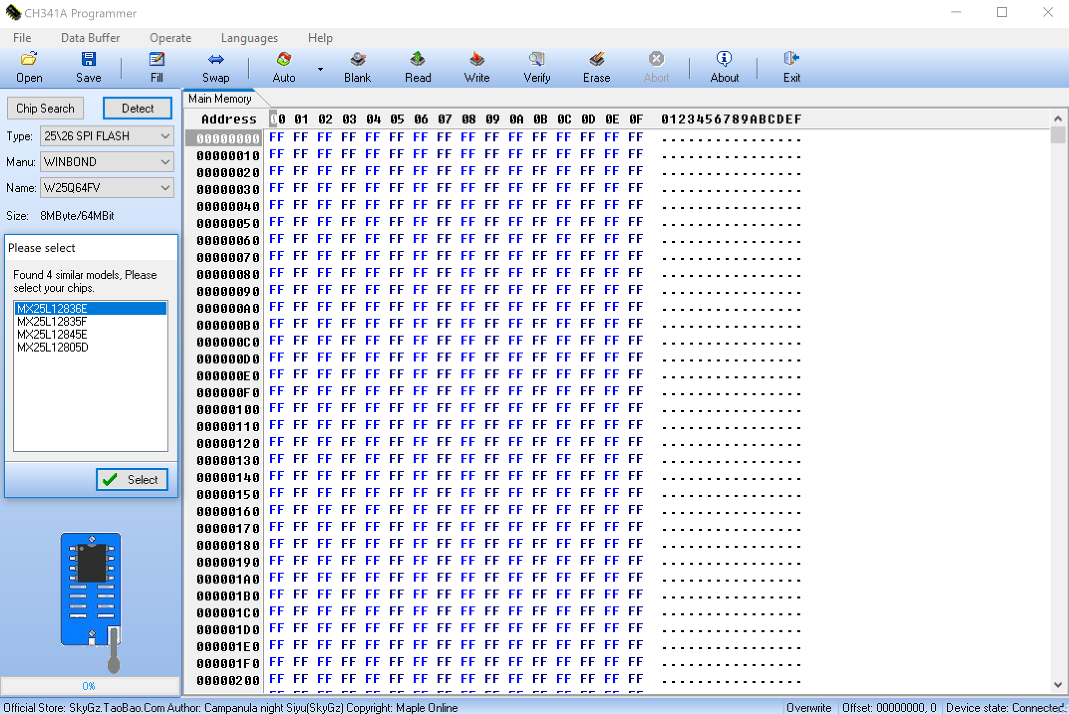
Which one of those should I choose? I guess the bios chip has also been modernized as the motherboard is only a couple of months old.
I’ve used the software and drivers provided in this package: APPS & DRIVERS
The guide I’m using is this one: BIOS FLASHING GUIDE
BTW: Should the motherboard light up in red as soon as the usb is connected to the Laptop with the CH341A App? I’ve tried to put on the clip correctly a couple of times and I’ve only succeeded on the sixth try. On the first try, the clip was a bit displaced. Can this damage the motherboard, especially since it draws current as soon as the CH341A it’s plugged into the computer?
Try version 1.34 instead, it’s in new link below (also try 1.30) And why do you have 64MB chip selected, close the app, reopen and click detect, then pick based off detection.
http://s000.tinyupload.com/index.php?fil…257455007472602
You mean onboard LEDs on the motherboard? Yes, that might be normal, not sure I’ve not used that board or any with LED Lighting like your board has. You wont damage the board but you can easily damage the BIOS legs, be careful and try to get it right first time and leave it without moving things around.
Thanks, I think I will follow this thread and also get myself a proper programmer so I don’t brick the BIOS on mine… I think this should be added as a sticky as another helpful tutorial (along w the other CH341A thread of course)
@Lost_N_BIOS - I tried it now with the 1.34 and I got some new suggestions in the drop-down menu. The closest number I can now find is the MX25L12873F:
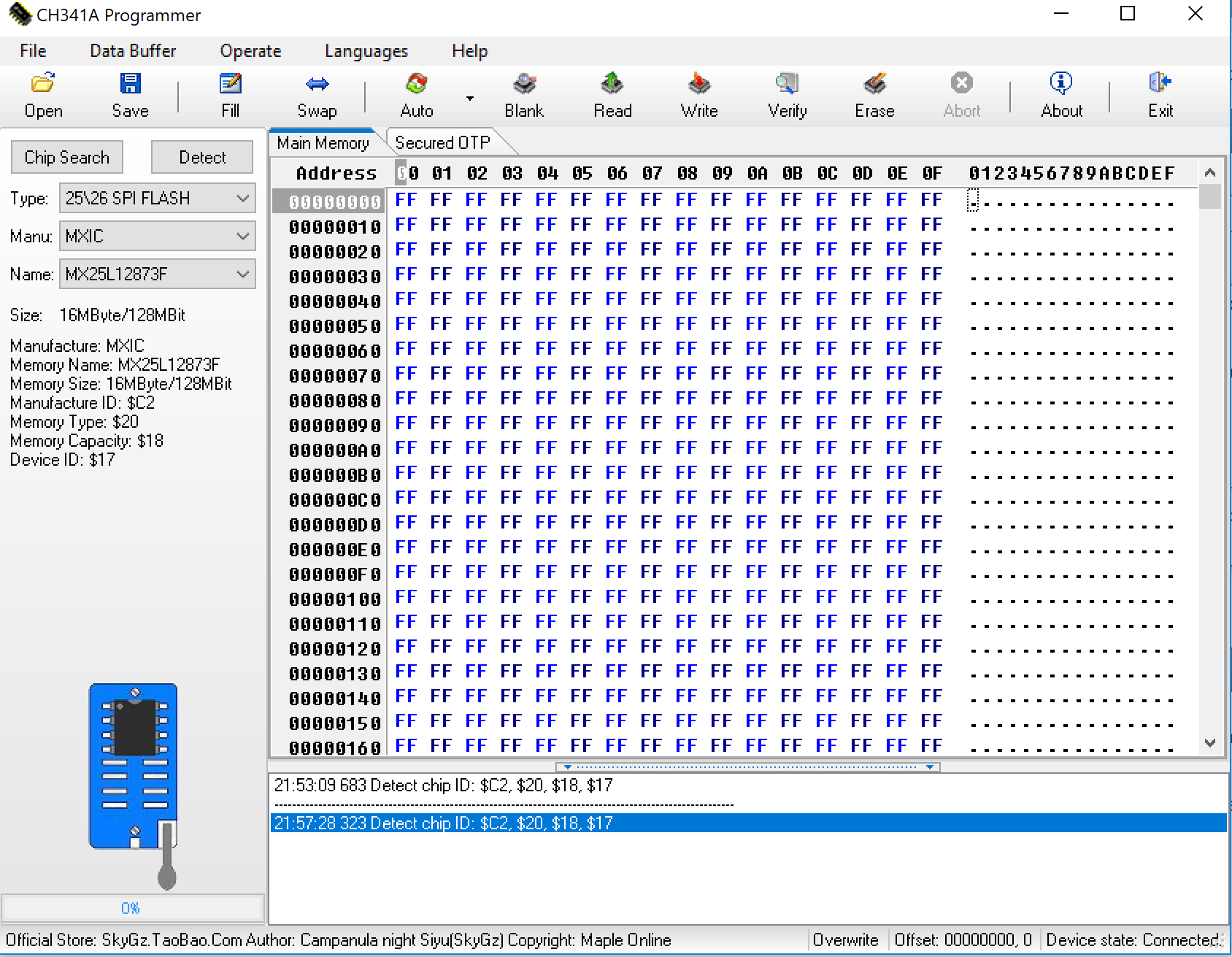
Only the 3 at the end is different. If it was a 2, then it woudl be the exact bios chip number that I have. Here’s my chip:
MX MANUAL
I haven’t selected anything in these tools. I just open them and click detect. The 64MB are there from the beginning. My bios cihp manual says it’s 128MBit, so I can manually change it if the detection goes wrong…
I have found this programmer app:
FlyPRO
This one has my chip in its database, but I’m not sure if it’s compatible with the CH341A…
Happy new year, everyone!
@Lost_N_BIOS - I have downloaded the 1.4 version from this site:
https://www.kazmielecom.com/2018/07/27/c…e-download.html
I read the chip and verified it afterwards, and here is the result:
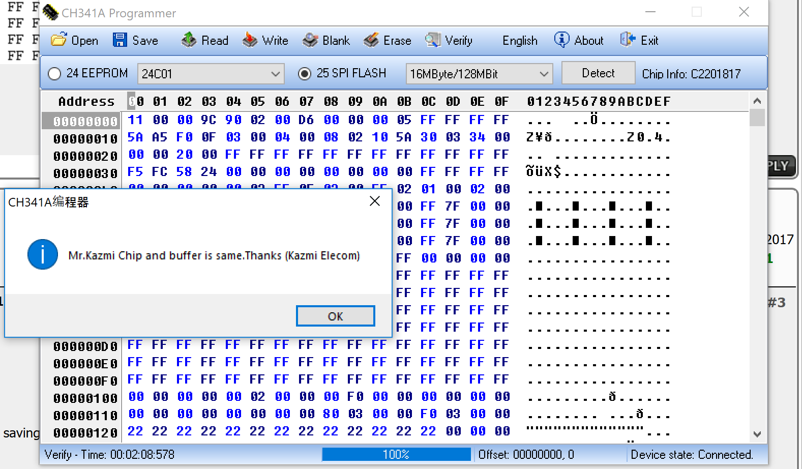
I set the size to 16MByte (128MBit) and the chip was automatically detected as C2201817, which is far from the number I see on my bios chip… Anyway, I did save the backup bios file that I created after the process was verified. When I open the backup bios inside a hex editor, it does show many different values instead of just FF or 00 values. Does that mean that the bios chip was correctly identified after all?
I’ve uploaded my backup file of the F5 firmware (BiosF5_Backup.bin) that’s currently on my main bios and I also included the official Gigabyte F5 version bios file (Z390DESI.F5):
https://www.sendspace.com/file/zmj1uf
Can I proceed with flashing process or should I wait until I find an application version that recognizes the correct chip name?
Thanks for the support so far! Much appreciated!
Can I proceed with the procedure above even though my BIOS chip’s label deviates from the automatically detected label?
And how can I insert the LAN MAC ID, BIOS ID into the new Firmware?
I already uploaded my backup of the F5 bios, but I’m not sure if the backup bios IDs match these IDs that I shot during the F9 bios info screen:
https://i.imgur.com/U5vzyAT.jpg
@Lumberjack - I reattached your images using forum software, as you can see on post #7, please continue to use attach feature because that is how the forum admin (Fernando) likes it, thanks. (And rest now too)
Sorry for not mentioning when I edited it earlier, I assumed you might notice and catch on 
1.4 version is actually 1.31(Free), that is why I sent you package to try 1.30 or 1.34, 1.34 is latest free version and is much newer than 1.31(free)/1.4, also included in that package is the version you are using but unedited (@ Mr.Kazmi - Kazmi Elecom etc)
I would use the ID you showed in the image of 1.34 version, last two digits are not needed anyway.
I do not know the outcome of the process you are trying to do, but I wouldn’t do that/ I would find version that correctly ID’s the chip and use that. That method may work, but it’s not correct way to do it, nor ideal, and is not suggested (May be OK, or may be saving corrupted file, may also write back incorrectly)
No, checking to ensure saved file is not all 00’s or FF’s is only a simple check and has nothing to do with chip ID or chip detection, you also need to compare it in several BIOS tools, does it open and look similar to your stock BIOS.
I will insert the MAC for you, it’s done by extracting GbE region and replacing GbE region with UEFITool, or via hex but since your original had MAC ID at two locations in the GbE and stock only one, replacement is better.
BIOS ID changes with each BIOS, so only same version BIOS will have same ID.
I checked your file and it looks OK, here is corrected file to use. if it fails to start after write/verify, then see what I explained above and use proper method instead, using 1.30 or 1.34
http://s000.tinyupload.com/index.php?fil…455334533495517
Happy New Year! Missed it last night 
@Lost_N_BIOS - thanks! I will attach the pics in the future.
Just to avoid any misunderstandings: So if I choose the chip MX25L12873F in the dropdown menu of 1.34, it will work, even though it’s not exactly MX25L12872F (label on my chip)?
I want to update the current, most probably corrupted (reboot loops), main bios to this version here (F6a):
http://download.gigabyte.eu/FileList/BIO…signare_f6a.zip
I’m sorry that I only now have provided the newest F6a bios version.
Is there a guide online somewhere that details the UEFITool replacement procedure?
@Lumberjack - Thanks!
On the chip ID, I don’t know, only you can find out by making a backup with that ID, if it verifies properly then it’s probably OK. Not all chip ID’s are in there, and never in full, for example W25Q64FV or W25Q64BV are in there for W25Q64, as is W25Q64 alone, but none have the full chip ID such as W25Q64FVSIG
I have attached the corrected BIOS above for you to try, that was F5, I didn’t know you wanted F6 or I would have done that one instead 
Yes, we have a UEFITool guide here in the forum, but I haven’t read it in a while so not sure what all it covers
[Guide] How to extract/insert/replace EFI BIOS modules by using the UEFITool
Here is F6a corrected with your LAN MAC ID, ready for your programmer
http://s000.tinyupload.com/index.php?fil…349558100221580
Thank you so much! I will try the update to F6a later on!
@Lost_N_BIOS - I did the update to the F6a version that you have uploaded in your last posting. The update itself was successful and I was able to start the computer normally - after going into the BIOS menu, I loaded the optimized defaults and I booted windows 10 afterwards. Windows 10 worked fine and so did the ethernet internet. However, once I shut the pc down and then tried to power it back on, the old reboot loop started…
Here’s the F9 menu screenshot I took to show that it was indeed updated to F6a (it used to be F5):
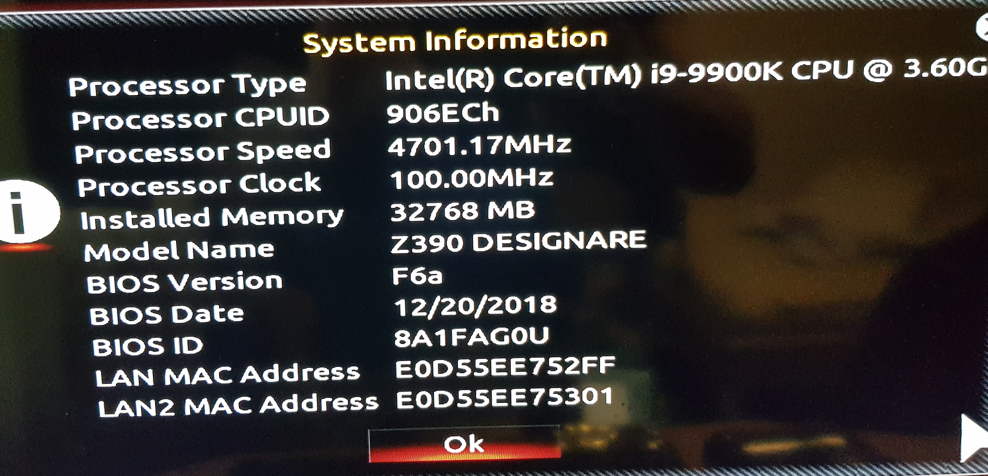
I think in this case, it only worked because I waited 12h plus… can this all be due to a simple bios update failure?
What’s worse is this: If I get into the 1.34 or the 1.40 version of the programmer app, it recognizes the chip but the motherboard LEDs do not light up like they used to before I did the update to F6a, and while I am able to read the chip, it somehow can’t erase it. Everytime I click on erase, it’s done after a second. When I click on blank, it tells me that not all values are set to 00 or FF…Maybe I have to wait 12h once again so that the motherboard lights up. Perhaps then I’ll be able to erase the chip and use the initial backup bios (F3) I made prior to the first bios flash…
This motherboard was nothing but an excrutiating experience. I’ll most likely declare it DOA tomorrow and ask for a substitute from the seller.
@Lumberjack - Plug the board in to a power source while using programmer, that may help. If not, use the version you used before. Onboard LEDs are really not a part of this process, if they light up or not is simply due to power delivery/lane layouts etc.
It may be normal for your board to light up, but certainly don’t base “It’s working” or not on that, however if you can’t erase or write to chip with LEDs out, then it could be related to “it’s working or not” in that case try the other version again that you had working before.
Go into windows, and run FPT and issue the following command, it should reboot automatically, but if not shut it down, remove all power from the board (disconnect power supply and remove CMOS battery), then press and hold power on button or short pins for 10-15 seconds, then short CMOS pins or press button for 10-15 seconds, then let sit for 1+ minute. Then put battery back, plug in PSU and try again, see how it acts. None of this power removal dance is required if after you issue the command below the board automatically reboots (It does same thing, only with internal command, both of these reset the ME State)
FPTw.exe -greset
BIOS update failure should not cause all this mess. Please try writing both BIOS to F6a, see if that helps too, if the above -greset does not.
@Lost_N_BIOS - So I can plug in the power cord into the PSU and turn the PSU switch on? Or do you mean to just plug in the power cord and leave the PSU switch in the off position?
Regarding the command: If Windows 10 starts properly on the affected PC and if I’m not stuck in a reboot loop, I can open the cmd.exe and execute the FPTw.exe -greset command. However, if I can’t access Windows, is there any other way?
As for writing the backup bios chip, too: Thankfully, Gigabyte have soldered in the backup bios in a very crowded space (thermal conductors etc.) where I can’t insert the SOIC8 clip…
Yes, but don’t power on the board. It’s not necessary, but you can test that if you want, see if that changes the LED effect with the software, since you seemed to think that mattered/was related to it working or not
FPT can be ran from DOS, inside the flash programming tool folder you will find DOS version.
To make backup BIOS match main, then you will need to use hotkey combo at startup (same time you normally use DEL to get into BIOS). Press Control + F10, sometimes you have to try a few times before you get it, if you see boot choice screen reboot and try again.
Best if you can use PS/2 KB, but if it doesn’t have PS/2, use USB 2.0 if it has it, and never wireless. If you get the “Swap BIOS” screens, reboot and use ALT+F10 instead. ALT/CTRL + F11 and F12 also have function, but I forget which all is which on UEFI BIOS